HAL Id: hal-00112496
https://hal.archives-ouvertes.fr/hal-00112496
Submitted on 31 Oct 2018HAL is a multi-disciplinary open access
archive for the deposit and dissemination of sci-entific research documents, whether they are pub-lished or not. The documents may come from teaching and research institutions in France or abroad, or from public or private research centers.
L’archive ouverte pluridisciplinaire HAL, est destinée au dépôt et à la diffusion de documents scientifiques de niveau recherche, publiés ou non, émanant des établissements d’enseignement et de recherche français ou étrangers, des laboratoires publics ou privés.
Finite elements applications: numerical tools and
specific fatigue problems
Habibou Maitournam
To cite this version:
Habibou Maitournam. Finite elements applications: numerical tools and specific fatigue problems. K. Dang Van, I. V. Papadopoulos. High-Cycle Metal Fatigue, from theory to applications, 392, Springer-Verlag, pp.169-187, 1999, 9783211831441. �hal-00112496�
ABSTRACT
FINITE ELEMENTS APPLICATIONS
NUMERICAL TOOLS AND SPECIFIC FATIGUE PROBLEMS
H. Maitournam
Ecole Polytechnique, Palaiseau, France
A systematic methodology for designing structures against high-cycle fatigue is developed. It relies upon: (i) computational methods for the calculation of the limit response of structures subjected to cyclic loading; (ii) numerical implementation of efficient high-cycle fatigue criteria. The first step in the prediction of high-cycle fatigue damage is the determination of stress cycles. In this paper we present three finite element procedures for the calculation of elastic-plastic structures subjected to cyclic loading (repeated moving contacts, small oscillatory contacts, etc.), namely the direct cyclic method, the stationary method and the simplified analysis of inelastic structures. These methods lead to easy determination of the possible stabilised response. Therefore, they avoid the lengthy repeated calculations performed with the classical finite element method and an incremental treatment of the loading history. The second step is the use of high-cycle fatigue criteria. We review some numerical tools for their implementations. Finally, some applications are presented. The first one is a problem of a cylinder subjected to an elliptical rotating pressure. The direct stationary method is used to determine the stabilised stress cycle and a macro-meso high-cycle fatigue criterion is used to detect crack initiation. The second application is the numerical simulation of a fretting fatigue map in relation with material fatigue properties.
1 INTRODUCTION
The systematic methodology for designing structures against high cycle fatigue we use, is summarized on figure 1. It consists in three uncoupled steps. The first one is the calculation of the mechanical stabilized state of the structures subjected to repeated loading ; the inputs needed are therefore the geometries of the structures, the materials they are made of, and the fatigue loading. The second step is the application of a crack initiation criterion with, as inputs, the intrinsic fatigue properties of the materials. And if necessary, a third step consisting in the use of propagation laws is performed.
1
STRUCTURAL ANALYSIS PROPAGATION &FAILURE •···l
specific methods for contact cyclic toads + Inelasticity
�-INITIATION UFETIME
Fig. 1: General methodology for designing structures against fatigue
The mechanical stabilized state of the structures designed against high cycle fatigue is necessarily elastic. But in most of repeated contact problems, the first
con-tacts generally generate plasticity setting up residual stresses, even in case of an elastic stabilized response (elastic shakedown). The quantification of those residual stresses is important in predicting the fatigue of such structures. It is well known that under a cyclic loading a rate independant elastic-plastic structure can have one of this four limit response : purely elastic, elastic shakedown or plastic shakedown, ratchetting. The possible mechanical stabilized state could be reached in few cycles or in an infinite number of cycles. It is therefore essential to have efficient numerical methods allowing a straightforward determination of this state. Classical finite element method with an incremental treatment of the loading history leeds to lenghty repeated calculations. The first part of this study is devoted to the presentation of three numerical proce dures for the direct calculation of the limit response of a structure subjected to cyclic loading : (i) the cyclic method (Dang Van et al.) for structures subjected to general cyclic loadings; (ii) the stationary method (Dang Van et al.) for structures subjected to moving loads; (iii) the simplified analysis of inelastic structures (Zarka et al.);
The second part of this paper is devoted to numerical analysis of fatigue. We describe how to numerically implement some fatigue criteria.
Finally, some applications are presented. The first one is a problem of rolling contact fatigue. It is represented by a cylinder subjected an elliptical rotating pressure. The direct stationary method is used to determinate the stabilized stress cycle. This limit state is necessarily elastic (or elastic shakedown) be avoid low cycle fatigue and incremental collapse. A macro-meso high cycle fatigue criterion is used to detect crack initiation. The second application is the numerical simulation of fretting fatigue tests on a particular experimental set-up considered as a structure. Fretting is the surface damage induced by small amplitude oscillatory displacements between components in contact. The direct cyclic method is used to evaluate the limit response of the structure. Then, we use macro-meso multiaxial fatigue criterion identified by classical fatigue tests to predict crack initiation.
2 DIRECT CYCLIC METHOD
As far as we are concerned by high cycle fatigue the limit response of the structure subjected to repeated loads is with elastic shakedown. The evolution towards this state is not important. The cyclic direct method allows the direct determination of the asymptotic response (i. e. stabilized mechanical state) of a structure subjected to a general cyclic loading without an incremental treatment of the whole loading history. The structure considered is made of von Mises elastoplastic material. It is subjected to a cyclic external loading composed of prescribed forces fd and displacements ud(t),
2.1 Principle of the method
We seek directly for the stabilized mechanical response of the structure by using the two following procedures :
(
i)
large time incremental method developed Ladeveze et al. ([9, 10]), departing form step by step scheme and using a single "large" increment of time ; (ii)
research of the solution in the space of periodic responses(
[11]).In the incremental method, the time interval [0, T] is discretized in n subintervals
0 < t
1
< ... < tn
= T. For each loading increment (!:J.fd, !:J.ud), the incremental quantities !:J.u, !:J.e, !:J.eP are evaluated such as to satisfy static, plastic and kinematic admissibility conditions. The loading path is followed step by step and cycle by cycle until the limit response is reached.The approach we propose here, is also iterative. But, it consists,
•
(
i)
first, in calculating , for the whole cycle, the statically and kinematically admissible responses
;
practically, we calculate this solution at the discrete instants t; of the cycle; for each iteration j, at instant t;, we determine the stress tensoru(, which satisfies equilibrium for the loading (fd(t,
)
) and the strain tensor E{, which respects with the prescribed displacements ud(
t,)
corresponding to instant t,; these two conditions are equivalent to the resolution of equilibrium equations; for instance, when a constant stiffness is used, they are given by :in which F,, F,P'-1 and K are the vector of nodal external forces corresponding to fd(t,), the vector of plastic forces due to plastic strain Ef1-1
(
assumed known) and the stiffness matrix of the linear elastic structure, respectively;• in a second stage, in determining for the whole cycle, the plastically admissible
response (the stress tensor u;
:
1, the plastic strain€
��
1, the internal parametersat(•+I))
; at each time, the plastic strain€
��
1 is obtained by projecting the strain increment€;+1-
E{ on the elastic convex defined by the initial state(
u(, E/1,at,)
p
at time t, which is known;
u;+l
is then calculated from the constitutive law written in incremental form :• The stabilized state is obtained when the plastic strain E1P' and the internal pa
rameters
(a�1)
are periodic i.e. their values at the beginning of the cycle are equal to those at the end of the cycle(
€�1
anda�n;
otherwise, the same steps areperformed in iteration j + 1 by initializing ( �::f1+1, o:
17
1) to ( E�1, o:1"!;
1) and the process is repeated until the obtention of elastic or plastic shakedown. Ratchetting is revealed by the non convergence of the procedure.
This method is typically used for fretting problems in which we are concerned by small oscillatory contacts.
3 STATIONARY METHODS
3.1 Recall of the principle of the 'stationary methods'
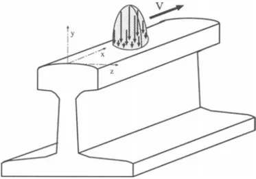
The method is applicable in the case of structures subjected to repeated moving loads. The full details of the 'stationary methods' used in this paper and their finite elements implementation can be found in [3]. Here, we just recall the principle of the analysis. Let us consider a prismatic structure made of an elastic-plastic material (let's say a rail) subjected to loads (let's say normal and tangential pressures) moving with a velocity
V= Vex (Fig. 2).
Fig. 2: Structure under repeated moving load
loads ; for any material quantity A, it leads to the following relation :
A. = -VA,x (1)
3.1.1 Mechanical problem
The first idea consists in writing the equations governing the mechanical problem in the moving loads reference. Thus one obtains [4] :
with -equations of motion -constitutive laws u = L: (e:::e- aBI) + Uo p - A8f -€ ,x- 8u f � 0, A 2: 0, Af = 0 f � 0, A 2: 0, Af = 0 1 8f 8f A = -((--8 :L:e:::,x+aB,xtr(-8 ))H u u ( = 1 if f = 0 (2) (3) (4) (5) (6) (7) (8) (9) (10)
(.) meaning positive part, and
( = 0 if f < 0 (11)
(12)
A is the plastic multiplier, (f = 0) defines the elastic domain, ke is the shear yield stress, a the coefficient of thermal expansion, (} the temperature elevation, u0 the ini
tial stress, ak are internal parameters and Ak their associated forces, L tensor of elastic coefficients, Z and l are assumed known.
In these equations time derivatives have been replaced by space derivatives, ac cording to (Eq. (1)). Their integrations are performed in space, along the direction of the motion of the loads; so that, numerically (using the finite element method), neither the load, nor the structure are translated. The plastic behaviour can be very gen eral, for instance, in [3, 4, 5] the von Mises isotropic and/or linear kinematic hardening material, the non-linear kinematic hardening law proposed by Bower [14] has been used.
The second idea is to use the stationarity of the limit state (in the absence of ratchetting the stress field and the internal variables are are periodic) in order to find its value directly. This condition is written as :
1
f.Pdt = 0cycle and (13)
The two following numerical procedures for the determination of the stabilized state are derived [3].
(i) The pass-by-pass stationary method (PPSM) for the calculation of a single pass; so by computing the successive passes by this method, one can find all the features of the "stabilized" state (numbers of cycles before reaching it, residual stresses, plastic deformations, etc). This "stabilized" state can, of course be ratchetting; in such a case, the ratchetting rate is immediately deduced as the increment of plastic strains caused by a pass.
(ii) The direct stationary method (DSM) for the direct determination of the "stabilized" state if it is a shakedown (elastic or plastic); The ratchetting is indicated by a non-convergence of the algorithm.
Thus, these methods allow the description of strains and stresses due to cyclicly and alternatively moving contacts, the quick determination of the nature of the sta bilized state (elastic shakedown, plastic shakedown or ratchetting). Such analyses of repeated contacts using shakedown principles were carried out with semi-analytical methods, by Johnson [15, 16, 17].
4 SIMPLIFIED A NALYSIS OF STRUCTURES
The Simplified Analysis of Inelastic Structures proposed by Zarka et al. [20] leads to the direct calculation of the limit cycle (elastic or plastic shakedown) for an elastic-plastic material subjected to cyclic loading. It is based on the introduction of transformed variables linearly related to the internal parameters, and on simple rules for the deter mination of theses variables in the limit cycle. Elastic analysis are then only needed.
5 NUMERICAL IMPLEMENTATION OF FATIGUE CRITERIA
The first step is the numerical determination of the stabilized response of the structure (elastic state or elastic shakedown). The application of the criteria is essentially local at each point of the stress evaluations. For a point M, the stress cycle for a period T is discretized in time, t1, t2, ... tn = T, n is the number of instants. The stress tensor u is
put in the 6-component vector form with, 0"1 = 0"11, 0"2 = 0"22, 0"3 = 0"33, 0"4 = 0"12, 0"5 =
cr23, cr5 = cr13. One defines :
(14) The stress deviator is S. It is defined in a 5-dimension space. (If for instance, we choose the stress deviator vector as 51 = (311 - 522)/2, 52 = (311 + 822)vf3j2, 83 = 833,84 =
812, 0"5 = cr23 then J2 =11 S 11).
5.1 implementation of criteria based on stress invariants
5.1.1 Calculation of
.jJ:;:
and� :
.jJ:;:
is the amplitude of the square root of the second invariant of the stress deviator.• as half of the longest chord, so it is simply determined by ;
(15) and in a detailled form
1
10 maxmax
2v2 i i (S1(t;)- S1(ti))2 + (S2(ti)- S2(ti))2 + (S3(ti)- S3(ti))2+ 2(S4(t;)- S4(ti))2 + 2(S5(t;)- S5(ti))2 + 2(S6(t;)- S6(ti))2 (16) In this case (see the contribution of I. Papadopoulos) the determinatioi_t of the mean value (
p;;.)
can be ambiguous.• as the elastic fluctuation :
(17)
This is a classical min-max problem, which can be solved by using the solution proposed by Papadopoulos, or using other numerical procedures given for instance in [21].
One defines S* as the stress deviator for which min8r max; 11 S( t;) - sT 11 is obtained. So,
p;;.
=�
mfx 11 S(t;)- S* 115.1.2 Calculation of L.H,a and L.H,m :
'L,H -,a -
�
2 ( �H ,max - �H . ),mzn 1 �H = -( �H ,111 2 ,max + �H . ) ,mzn (18) (19) (20) (21) (22)5.2 Implementation of criteria based on critical planes
5.2.1 Calculation of Ca and Cm : • As the longest projection chord
Ca =
t
max; maxj 11 e(t;)- e(tj) 111 /�_:______:._�--- (23)
= 2max;maxj y(Cl (t;)- C1(tj))2 + (C2(t;)- C2(tj))2 + (C3(t;)- C3(tj))2 In this case (see the contribution of I. Papadopoulos) the determination of the mean value (Cm) can be ambiguous.
• as the elastic fluctuation :
Ca = minmax 11 e(t;)- eT 11
er ' (24)
One defines e• as the shear stress for which miner max; 11 e(t;) - eT 11 is obtained. So,
Cm = max ' 11 e(t;) -e• 11 (25)
5.3 Macro-mesa approach implementation
Dang Van et Papapoulos ([2]) criteria implementation needs the calculations of the
microscopic stresses u(t;), which are the sum of the macroscopic stress �(M, t;) and the microscopic residual stresses p :
�(M, t;) = A(M)u(M, t;) + p(m, t;) (26)
A is the localisation tensor.
The assumption of elastic shakedown for the microscopic stresses leads for time independant microscopic residual stresses ( S*). They are are evaluated by the following min-max problem :
�
min max 11 5EL(M, i;)- ST 11= k*v 2 sr t,
S* := min max 8r 11 5EL(M, i;)- 5T 11
t,
(27)
(28)
Papadopoulos gives a method for solving this problem. Another method, based on Faisible Sequential Quadratic Programming, can be found in [21].
6 APP LICATION TO ROLLING CONTACT
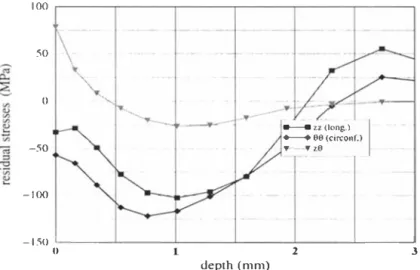
The first example is that of a rotation of a solid over a cylinder (Fig. 3). The contact surface is assumed to be elliptical with semi-axes a et b. a is the semi-axe along the longitudinal direction b the semi-axe along the circonferential one. The ratio a/b is fixed to 5. The material constants are : E (Young modulus) = 210 GPa, v (Poisson
coefficient) = 0.3, k (shear yield strenght) = 200 MP a. The pressure distribution is
also assumed to be elliptical with maximum pressure P0 = 800 MPa. The limit state reached is an elastic shakedown. The residual stresses obtained are shown on figure 4 .
..
• 7 .�
Fig. 3: Cylinder under rotating contact
100 .---r---.---,---�---.---, 50 0 -. ... __ ---50 -100 • -_,. ---:If" --'-/ a--11 zz (lons.l
I
- 66 (coreonf.l ,. "•6 - 1.�0 .__ ____ _._ ____ ___, ______ _!_ ____ ---�. ______ _.L_ ____ _.J 0 2 3 depth (mm)Fig. 4: Residual stresses obtained after repeated rolling (po/k
The application of fatigue criteria over the whole structure leads to a critical point located at the surface. On figure 5 we show in the ( T, p) diagram, loading paths
for different depths below the contact.
- material line +--+ depth= 2.67 b - depth=1.76b ---- depth = 1.1 b --- depth= 0.61 b --- depth = 0.256 b ... depth = 0. o �--��--�- -��--�--�----�--�--�� -600 -500 -400 -300 -200 -100 0 100 200 hydrostatic pressure p
Fig. 5: Loading path for different depths at the contact center (po/ k = 4., f1 = 0.)
7 APPLICATION TO FRETTING
7.1 Fretting fatigue problem
This section is devoted to the numerical simulation of a fretting test. The experimental set-up is presented in [12] and in [1]. Two cylindrical fretting pads (diameter 10 mm) are clamped against the two surfaces of a flat uniaxial fatigue specimen tested under constant amplitude loading at a frequency of 20 Hz. The pads are made of 100C6 steel and the fatigue specimen is made of 3Cr-MoV steel. The mechanical properties are given below :
Yield strength Tensile strength Young modulus Hardness
(MPa) (MP a) (GPa) (Hv)
3Cr-MoV 980 1140 215 360
The prescribed oscillatory between the pads are linked to the prescribed oscillatory fatigue stress S(t) in the specimen. For a maximum stress Smax=500 MPa, the am plitude of displacement is 0.55 f.1m. The flexible beams are equiped with strain gauge
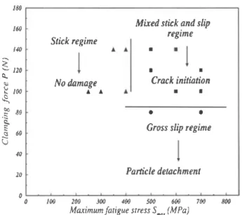
in order to measure the clamping force P between pads and specimen and the friction force related to the displacements accommodation. The variations of the tangential force T( t) are recorded for each cycle fatigue and plotted as function of fretting fatigue stress S ( t) (fretting fatigue loops). By varying the operating parameters ( P, Smax), three regimes are established:
• Stick regime : Fretting fatigue loops keep a non evolutive closed shape. Loops
are quite linear during the test. The macroscopic displacement between the contacting surfaces is mainly accommodated by elastic deformation in the near surface of the two components. No damage (wear or crack nucleation) appears during the 107 cycles of the test.
• Mixed stick-slip regime : Loops present an elliptical closed shape. There is partial
slip and fatigue crack nucleation observed at the edges of the contact.
• Gross slip regime : Loops present a trapezoidal shape. Full slip occurs between
the two contacting surfaces. In this regime, particle detachment is observed. The differents regimes are obtained for differents varying parameters ( P, Smax) summarized in the map shown in Fig. 8.
7.2 Numerical prediction of wear and crack nucleation
The prediction of damage mechanisms carried in the map Fig. 8 requires first the calculation of the stresses history in the stabilized state. Secondly, Dang Van multiaxial fatigue criterion is applied if the stabilized state is elastic shakedown.
The direct cyclic method described in Sec. 2 is used here to simulate the set-up and to calculate the stresses history in the stabilized state. The specimen is modeled as a half space subjected to a constant normal force and a varying tangential force T(t)
ami a fatigue stress S(t) varying linearly with T (t). The material is elastoplastic with a kinematical hardening (hardening modulus C=30 GPa) and with properties given in the previous subsection.
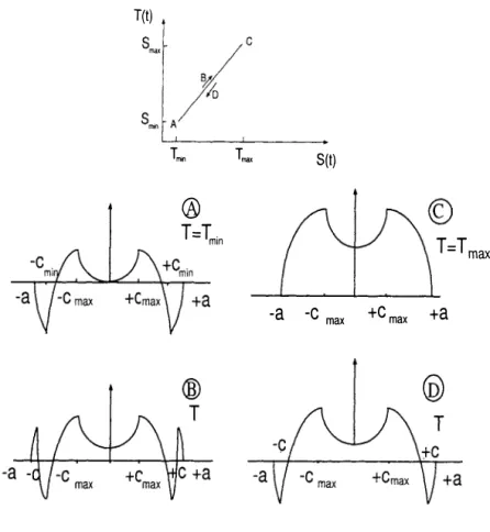
Three cases are performed corresponding to the three regimes established in the map ( P and Smax are the prescribed parameters and T max is measured in the test).
T(t) Tmn Tmax S(t)
®
T = Tmin T=T max -a -C max +C max +aFig. 6: loading path during fretting
• Mixed stick-slip regime P=100 N, Smax=600 MPa and Tmax=80 N (crack nucle
ation)
• Gross slip regime P=80 N, Smax=500 MPa and Tmax=64 N (wear)
In the case of loading in gross slip regime, the nonlinear stress-plastic strain cycles for an element located at the surface under the contact zone (x = -0.4a) are shown in Fig. 10 illustrating plastic shakedown. Wear is then associated with plastic sakedown and so to low cycle fatigue properties confirming the works of Ludema [13] and John san [15]. Owing to this numerical method, we obtain, better still, the plastic strain amplitude in the stabilized state.
Since the response of material is respectively purely elastic and elastic shakedown in stick regime and mixed stick-slip regime, high cycle fatigue is concerned. The stress
T(t) ®
T =-Tmax
-a
+a
w.
Fig. 7: loading path during fretting
®
-a
+a
®-eh
T=O -c +C-a v
\)•a
cycle through the contact is multiaxial. Uniaxia.l empirical high cycle fatigue criterion are not applicable. As done in [12], Dang Van multiaxial fatigue crack nucleation cri terion is used to predict fatigue cracks. The fatigue properties of the material obtained by torsion t and bending f fatigue tests (i=380 MPa and f=594 MPa for 30NCD16
steel). More details about the Dang Van multiaxial fatigue crack nucleation criterion arc given in references [18, 19]. The most critical point is located in the surface at
the edge of the contact. The most critical loading path ( T ,p) for each regime resulting
from the stress cycles in the stabilized state are plotted in Dang Van's fatigue Diagram shown in Fig. 11. In stick regime, the loading path ( T ,p) is beneath the fatigue line
material, so, no damage occurs. And in mixed stick-slip regime, the loading path in tersects the fatigue line material concluding of crack failure. The prediction of crack initiation is in good agreement with the experimental observations.
180 /6() 140 --.. <: '- 120 0... � 100 � CO 80 .s � 60 c:s G 40 20 0 0 Stick regime No damage • •
Mixed stick and slip regime • • • Crack initiation • • • • Gross slip regime
Particle deu:zchment
I 00 200 JOO 400 500 600 700 800
Maximum fatigue slress S...., (MPa)
Fig. 8: Fretting map (Petiot et al, [12])
� "" c. 6 '0� � � 1::; "-<:l ., � 0.0 ·500.0
•1000·�31...:_0---.z�.s=----.-:z.:-o ---:.f':.s---.J-:-:.o;---,p-: .. -;5 ---;;o_';;o---;;o.s Plastic shear strain E0.,( 10._)
Fig. 10: Plastic strain cycle in gross slip regime (x = -0.4a)
600.0 500.0 c. 400.0 6 .. � � 300.0 -� "' � � -� 200.0 ::0 100.0 -0.0 -400.0 -200.0 0.0 200.0 600.0
Hydrostatic p�urt p (MPa)
Fig. 11: Loading path in Dang Van's diagram, for stick reg1me and
References
[1] N. Maouche, M.H. Maitournam, K. Dang Van (1997), On a new method of eval uation of the inelastic state due to moving contacts, Wear 203-204, pp 139-147. [2] P. Ballard, K. Dang Van, A. Deperrois and Y. Papadopoulos (1995), High cycle
fatigue and a finite element analysis, Fatigue Fract. Engng Mater. Struct. Vol. 18, N° 3, pp. 397-411.
[3] K. Dang Van & M.H. Maitournam (1993), Steady-state flow in classical elasto plasticity : application to repeated rolling and sliding contact, J .Mech.Phys.solids Vol.41, W 11, pp. 1691-1710.
[4] K. Dang Van and M.H. Maitournam (1994), Thermomechanical state near rolling contact area, Dissipative Processes in tribology, Edited by D. Dowson et al., El sivier Science B.V. pp. 423-428.
[5] K. Dang Van and M.H. Maitournam (1994), Elastoplastic Calculations of the Mechanical State in Alternative Moving Contacts: Application to Fretting Fatigue,
FRE T TING FA TIGUE, ESIS 18 (Edited by R.B. Waterhouse and T.C. Lindley), Mechanical Engineering Publications, London, pp. 161-168.
[6] 0. Vingsbo, S. Soderberg (1988), On fretting maps, Wear 126 pp. 131-147. [7] L. Vincent, Y. Bertier, M. Godet (1992), testing methods in fretting fatigue: a
critical appraisal, standardisation of fretting fatigue test methods and equipement, in M. Helmi Attia and R. B. Waterhouse (eds), ASTM STP 1159, American Society for Testing and Materials, Philadelphia, pp. 33-48.
[8] R.D. Mindlin (1949), Compliance of elastic bodies in contact, J.Appl.Mech Vol.16, pp.259-268.
[9] P. Ladeveze (1989), La methode a grand increment pour !'analyse de structures a
comportement non lineaire decrit par variables intemes, C.R.A. S 309, Serie II, No
11, pp. 1095-1099.
[10] Ph. Boisse, P. Ladeveze, P. Rougee (1989),A large time increment method for elastoplastic problems, Eur.J.Mech, A/solids, No 4, pp. 257-275.
[11] S. Akel, Q.S. Nguyen (1989), Determination of the limit response in cyclic plastic ity,Proceedings of the 2nd International Conference on Computational plasticity:
Models,Software and Applications ( Edited D.R.J. Owen, E.Hinton, E. Onate), Pineridge Press, Swansea, pp. 639-650.
Finite Elements Applications 187
[12] C. Petiot, L. Vincent, K. Dang Van, N. Maouche, J. Foulquier, B. Journet (1995), An analysis of fretting-fatigue failure combined with numerical calculations to pre
dict crack nucleation, Wear 181-183 pp. 101-111.
[13] K. Kim, K.C. Ludema (1995), A correlation between Low cycle fatigue and scuffing properties of 4340 steel, Wear 117 pp. 617-621.
[14] A.F. Bower (1989), Cyclic hardening properties of hard-drawn copper and rail steel, J. Mech. Phy. Solids, 37(4) 455-470.
[15] K.L. Johnson (1995),Contact mechanics and wear of metals, Wear 190 pp. 162-170. [16] K.L. Johnson (1992), The application of shakedown principles in rolling and sliding
contact, Eur. J. Mech., A/Solids 11 Special Issue 155-172.
[17] K.L. Johnson (1985), Contact mechanics, Cambridge University Press.
[18] K. Dang Van, B. Griveau, 0. Message (1982), On a new multiaxial fatigue limit criterion: theory and application, biaxial and multiaxial fatigue, in M.W. Brown and K. Miller (eds), EGF Publication 3, pp.479-496.
[19] K. Dang Van (1993), Macro-micro approach in high-cycle multiaxial fatigue, in D.L. McDowell and R. Ellis (eds), Advances in multiaxial fatigue, ASTM STP 1991, American Society for testing and Materials, Philadelphia, pp. 120-130. [20] J. Zarka, J. Frelat, G. Inglebert & P. N avidi, A new Approach to Inelastic Analysis
of Structures (1989), Martinus Nijhoff Publisher.
[21] J.L. Zhou, A.L Tits (1993), Non monotonic line search for minimax problems, J. Optim. Theory Appl. 76, 455-476.