HAL Id: hal-01439212
https://hal.archives-ouvertes.fr/hal-01439212
Submitted on 18 Jan 2017
HAL is a multi-disciplinary open access
archive for the deposit and dissemination of
sci-entific research documents, whether they are
pub-lished or not. The documents may come from
teaching and research institutions in France or
abroad, or from public or private research centers.
L’archive ouverte pluridisciplinaire HAL, est
destinée au dépôt et à la diffusion de documents
scientifiques de niveau recherche, publiés ou non,
émanant des établissements d’enseignement et de
recherche français ou étrangers, des laboratoires
publics ou privés.
Ka-Band Satellite Communications
Simon Mener, Raphaël Gillard, Langis Roy
To cite this version:
Simon Mener, Raphaël Gillard, Langis Roy. A Dual-Band Dual-Circular Polarization Antenna for
Ka-Band Satellite Communications. IEEE Antennas and Wireless Propagation Letters, Institute of
Electrical and Electronics Engineers, 2017, 16, pp.274 - 277. �10.1109/LAWP.2016.2572261�.
�hal-01439212�
Abstract— A novel Ka-band dual-band dual circularly polarized
antenna array is presented in this letter. A dual-band antenna with left-hand circular polarization for the Ka-band downlink frequencies and right-hand circular polarization for the Ka-band uplink frequencies is realized with compact annular ring slots. By applying the sequential rotation technique, a 2×2 subarray with good performance is obtained. This paper describes the design process and presents simulation and measurement results.
Index Terms— Antenna array, dual circular polarization, dual
frequency, annular slot, sequential rotation technique.
I. INTRODUCTION
ecause satellite communication (SatCom) systems having large capacities are in demand, new SatCom antennas using the Ka-band are being investigated. This higher operating frequency provides at the same time high data rate links and miniaturized antenna systems [1]. In terms of choice of polarization, circularly polarized (CP) microstrip antennas [2-5] are most attractive because they can facilitate orientation between transmitter and receiver and are highly suitable for mobility, weather penetration, and reduction of multipath reflections [6]. The proposed antenna system therefore exhibits dual band functionality with dual-circularly polarization operation to provide an independent single beam with a large steering range in each band: uplink from 30 GHz to 31 GHz with Right-Hand CP and downlink from 20 GHz to 21 GHz with Left-Hand CP. Recent developments mainly use parabolic antennas with mechanical beam coverage [7-10] or multilayer configurations [11-12] with a significant cost. Microstrip antennas are widely preferred especially when profile, size, weight, compatibly with other integrated circuitry and costs are of main concern. In recent years, only a few investigations of Ka-band SatCom antennas operating under circular-polarization have been carried out. In [13], a multiple series-parallel sequential rotation feeding network for 64 elements is presented but only for a single band. Dual-CP operation has been demonstrated using a mechanical polarization screen [14] or by using the stacked patch technique [15].
In comparison to this design, as introduced in [16], the proposed antenna is fabricated only on two layers and employs multiple annular slots to provide dual-band dual-CP operation in Ka-band with low profile, low return loss, very low axial ratio and narrow beam coverage of ±30°.
This work was supported by the Direction Générale de l’Armement (DGA) of France and the Natural Sciences and Engineering Research Council (NSERC) of Canada.
S. Mener and R. Gillard are with the Institute of Electronics and Telecommunications of Rennes, INSA, UMR CNRS 6164, 35708 Rennes (e-mail: [email protected]).
L. Roy is with the Department of Electronics, Carleton University, Ottawa, ON K1S5B6, Canada (e-mail: [email protected]).
It uses sequential rotation to obtain a broad impedance and axial-ratio bandwidth.
In Section II, the measurement of miniaturized single elements using annular slots is presented and the dual-band dual-CP principle is explained. Section III summarizes the performance of experimental 2×2 subarrays with dual-band dual-CP capability. Finally, in Section IV, conclusions are drawn.
II. EXPERIMENTAL VALIDATION OF MINIATURIZED ELEMENTS FOR DUAL-BAND DUAL-CP
Printed slot antennas have attractive features compared to patch antennas: larger bandwidth, lower profile and lower conductor loss [6]. Moreover, they can easily produce two different operating frequency bands and CP radiation [17-22]. The proposed radiating element (Fig. 1) then consists of two miniaturized annular ring slots. The larger slot operates at 20.5 GHz and is LH circularly polarized while the smaller one operates at 30.5 GHz and is RH circularly polarized. Each slot is fed by 2 microstrip lines with phase quadrature in order to produce CP. CP could also be obtained from a single feedline by adding stubs to the annular ring slot (as in [23]) or by using a L-shape microstrip line (as in [24]). However, it is well-known [6]-[25] that 2 feedlines improve the overall CP bandwidth. The chosen substrate is the moderately high permittivity Rogers TMM10i substrate (h=0.38mm, εr=9.8) supporting the metallic
ground plane (including the annular ring slots) and the feedlines. It is glued with a 3M bonding film on a 4mm-thick low-permittivity foam layer. The height h between the radiating elements and the additional ground plane is optimized to 4mm (cf. Fig. 1).
Both elements can be accommodated in a 7×7 mm2 lattice. This corresponds to an array with 0.5λ0 and 0.7λ0 inter-element
spacing at 20 and 30 GHz respectively, thus allowing beam scanning up to ±60° and ±30° for downlink and uplink.
(a) (b)
Fig. 1. Proposed dual-band dual-CP antenna with miniaturized annular ring slots in Ka-band. (a) Top view: a=7mm, R1=1.25mm, R2=0.95mm, R3=0.9mm,
R4=0.6mm (b) 3D view: h=4mm.
A Dual-Band Dual-Circular Polarization
Antenna for Ka-Band Satellite Communications
Simon Mener, Raphael Gillard, Langis Roy
Each slot element has first been optimized individually with the HFSS commercial software package. Prototypes have then been fabricated and tested. They are shown in Fig. 2. The experimental results of reflection coefficient, gain, and axial ratio against frequency or elevation angle θ are shown in Fig. 3-5, respectively. Note that during the measurements, an absorbing layer is placed behind each antenna to suppress backward radiations and associated disturbances.
(a) (b) (c) (d)
Fig. 2. Pictures of the fabricated miniaturized annular ring slot antennas in Ka-band. (a) Back view of the 20 GHz-band prototype. (b) Front view of the 20 GHz-band prototype. (c) Back view of the 30 GHz-band prototype. (d) Front view of the 30 GHz-band prototype.
(a) (b)
Fig. 3. Simulated and measured reflection coefficient of the miniaturized annular slot antennas. (a) 20 GHz-band. (b) 30 GHz-band.
(a) (b)
Fig. 4. Simulated and measured gain of the miniaturized annular slot antennas. (a) 20.5 GHz in the x-z plane. (b) 30.5 GHz in the x-z plane.
(a) (b)
Fig. 5. Simulated and measured axial ratio of the miniaturized annular slot antennas. (a) 20.5 GHz in the x-z plane. (b) 30.5 GHz in the x-z plane.
In Fig. 3, both the measured and simulated -10dB reflection coefficient cover the [19.5-21.5] GHz and [29-31]
GHz bands for the downlink and uplink antenna respectively. The shift (uplink band) of the measured reflection coefficient towards the lower frequency are attributed to fabrication imperfections and perturbations brought by the connector. In Fig. 4, the measured gain in each band agrees well with the simulated value (measured maximum gain in the broadside direction Gmax is 1.2 dB and 1 dB for the downlink and uplink
antennas, respectively). Note that an additional ground plane is required to suppress backward radiations and to obtain a higher gain. The measured gain of the Tx element is noisy, because of the small dynamic range of the test setup and also due to the perturbation by the connector. Fig. 5 shows the measured and simulated axial ratios. The measured results are not as good as the simulated performance: ARsimu=2.5dB and ARmeas=4.1dB at
20.5 GHz and ARsimu=1.4dB and ARmeas=3.2dB at 30.5 GHz, in
the broadside direction.
In the next section, we demonstrate how this initial performance may be improved at the array level using sequential rotation.
III. FOUR-ELEMENT SUBARRAY MEASUREMENT
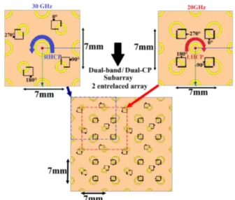
Two 2×2 subarrays are now studied. These are formed by four annular ring slots arranged sequentially in orientation and in phase to achieve radiation symmetry, to cancel undesirable higher-order modes and to obtain purer polarization [26]. For the sake of simplicity, 2 different subarrays will be considered as shown in Fig. 6. In the first one, four slots working at 20 GHz are fed using sequential rotation and in the second one, the same process is applied to four slots working at 30 GHz. Non excited elements working in the other band are also included to account for possible mutual coupling. Both subarrays can thus be seen as specific sets of elements extracted from a larger interlaced array (as shown in Fig. 6).
Fig. 6. Dual-band/ Dual-CP concept: two interlaced arrays with appropriate sequential rotation in Ka-band.
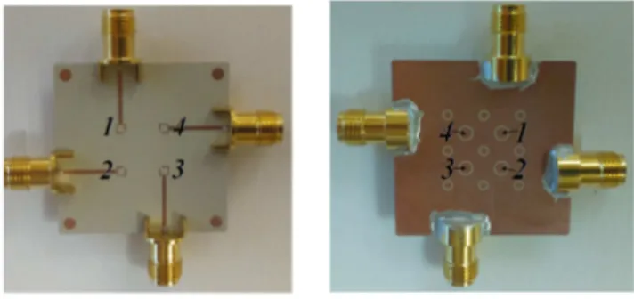
To demonstrate the proposed concept, a prototype of each subarray has been fabricated and tested. Their pictures are shown in Figs. 7 and 8, respectively for the 20 GHz-band and 30 GHz-band.
(a) (b)
Fig. 7. Pictures of the fabricated subarray composed of four elements in sequential rotation in the 20 GHz-band. (a) Back view. (b) Front view.
(a) (b)
Fig. 8. Pictures of the fabricated subarray composed of four elements in sequential rotation in the 30 GHz-band. (a) Back view. (b) Front view.
The simulated and experimental S-parameter results are presented in Figs 9 and 10 for the 20and 30 GHz-subarrays respectively.
(a) (b)
Fig. 9. Simulated and measured reflection coefficient of the 2×2 subarray against frequency. (a) 20 GHz-band. (b) 30 GHz-band.
(a) (b)
Fig. 10. Simulated and measured transmission coefficient of the 2×2 subarray against frequency. (a) 20 GHz-band. (b) 30 GHz-band.
The coupling between ports is lower than -19dB across the entire bandwidth. Moreover, a very good reflection coefficient is obtained for each port at the central frequency (S11/S22/S33/S44≤-16dB in the two frequency-bands). The large
difference between simulation and measurement is mainly due to the fabrication and assembly imperfections and the effect of the connector. The experimental radiation pattern in circular polarization is plotted in Fig. 11 for both frequency bands against elevation angle θ. Note that during the measurements, an absorbing layer is placed behind each subarray. For completeness, the axial ratio of both subarrays is shown in Fig. 12 against frequency for the broadside direction.
In Fig. 11, the measured gain in each band agrees well with the simulated result (measured maximum gain in the broadside direction Gmax is 4 dB and 5 dB for the 20 and 30
GHz-subarrays respectively). The improvement of the axial ratio is clearly demonstrated in the broadside direction: the axial ratio bandwidths of 3 dB are better than 3GHz for both frequency bands. Beam coverage of ±30° can thus be obtained for the downlink and uplink frequencies.
(a) (b)
Fig. 11. Simulated and measured gain of the 2×2 subarray. (a) 20.5 GHz in the x-z plane. (b) 30.5 GHz in the x-z plane.
(a) (b)
Fig. 12. Simulated and measured axial ratios for a broadside direction (θ=0°) against frequency. (a) 20 GHz-band. (b) 30 GHz-band.
IV. CONCLUSION
A novel Ka-band dual-band dual-CP antenna array is presented in this letter. Two interlaced arrays each using an appropriate sequential rotation have been applied to improve the polarization purity and to generate a LHCP radiation on the downlink frequencies and a RHCP radiation of the uplink frequencies. Both measured and simulated results verified the validity of the proposed concept. The results show that the proposed 2×2 subarrays have good radiation patterns and high polarization purity (axial ratio at broadside less than 1.5 dB and 0.5 dB respectively) over a frequency band of 19-22 GHz and 29-32 GHz.
REFERENCES
[1] L. Marcellini, R. Lo Forti, and G. Bellaveglia, “Future developments trend for Ku and Ka antenna for satcom on the move,” in Antennas and Propagation (EUCAP), Proceedings of the 5th European Conference on, Apr. 2011, pp. 2346 –2350.
[2] B. H. Uhl, M. Dawood, and S. Castillo, “Quadrature-modulated circular microstrip patch antenna for phased arrays,” IEEE Antennas Wireless
Propag. Lett., vol. 9, pp. 958–961, 2010.
[3] S. Gao, Y. Qin, and A. Sambell, “Low-cost broadband circularly polarized printed antennas and array,” IEEE Antennas Propag. Mag., vol.49, no. 4, pp. 57–64, Aug. 2007.
[4] D.-C. Chung, C.-H. Yun, K.-H. An, S.-H. Lim, S.-Y. Choi, B.-S. Han, J.-H. Oh, M.-J.-H. Kwak, S.-J.-H. Jung, K.-Y. Kang, S.-K. Han, J.-S. Hwang, T.-H. Sung, and T.-H.-S. Choi, “HTS microstrip antenna array for circular polarization with cryostat,” IEEE Trans. Appl. Supercond., vol. 15, no. 2, pp. 1048–1051, Jun. 2005.
[5] Nasimuddin, Z. N. Chen, and K. P. Esselle, “Wideband circularly polarized microstrip antenna array using a new single feed network,”
Microw. Opt. Technol. Lett., vol. 50, no. 7, pp. 1784–1789, 2008.
[6] R.Garg, P. Bhartia, I. Bahl, and A. Ittipiboon, Microstrip Antenna Design
Handbook. Boston, MA: Artech House, 2000.
[7] D. Khalil, "Satcom-On-The-Move Presentation," SATCOM / Space
Systems, S&TCD, CERDEC.
[8] J. S. Kot, I. M. Davis, C. Granet, G. Pope, ‘Antenna concepts for Ka-band SATCOM on the move’, MilCIS 2009, Canberra, 10-12 Nov. 2009. [9] J. S. Kot, I. M. Davis, C. Granet, G. Pope, ‘Compact Shaped Dual-Reflector System For Military Ka-band SATCOM on the move’, in
Antennas and Propagation (EUCAP), Proceedings of the 5th European
Conference on, Apr. 2011, pp. 3518 –3521.
[10] H. Bayer, A. Krauss, R. Stephan, M. A. Hein, ‘Land-Mobile Ka-Band Satcom Tracking Antenna Employing a Printed Circuit Board Based Multimode Monopulse Feed’, Antennas and Preopagation in Wireless
Communications (APWC), 3-9 Aug 2014, pp. 296-299.
[11] E. Meniconi, V. Ziegler, R. Sorrentino und T. Chaloun ,‘3D integration technologies for a planar dual band active array in Ka-band’ European
Microwave Conference , pp 215-218. 2013
[12] W F. Greco, G. Amendola, E. Arnieri, L. Boccia, and A. Sandhu, “A Dual-Band, Dual-Polarized Array Element for Ka Band Satcom on the Move Terminals,” 8th European Conference on Antennas and
Propagation (EuCAP), Apr. 2014, pp. 2432–2435.
[13] A. Chen, Y. Zhang, Z. Chen, and C. Yang, “Development of a Ka-band wideband circularly polarized 64-element microstrip antenna array with double application of the sequential rotation feeding technique,” IEEE
Antennas and Wireless Propagation Letters, vol. 10, pp. 1270–1273,
2011.
[14] R. Lenormand, J.L. Almeida, J.F. David, A. Valero-Nogueira, J.I. Herranz-Herruzo, “Antenne mobile large bande `a commutation de polarisation” French patent FR1103536, 2014.
[15] B. Rohrdantz, T. Jaschke, K. Frauke, H. Gellersen, F. Jacob, ‘A dual-frequency and dual-polarized patch antenna at Ka-band’, Proceedings of
the 45th European Microwave Conference, 7-10 Sept. 2015, pp.
1495-1498, Paris, France.
[16] G. Amendola, E. Arnieri, L. Boccia, E. Ziegler, ‘Annular ring slot radiating element for integrated millimeter wave arrays’, Proceedings of
6th European Conference on Antennas and Propagation, EuCAP 2012,
pp. 3082-3085, Prague, Czech Republic, 26 March, 2012.
[17] W. Ren, J. Y. Deng, S. H. Hong, and K. S. Chen, “Design of dual-band circularly polarized annular slot antenna for wireless local area network applications,”, vol. 42, no. 8, pp. 1306–1309, Aug. 2008.
[18] C. H. Cai, J. S. Row, and K. L. Wong, “Dual-frequency microstrip antenna with dual circular polarization,” Electron Lett., vol. 42, no. 22, pp. 1261–1262, Oct. 2006.
[19] X. Bao and M. J. Ammann, “Dual-Frequency dual-sense circularly polarized slot antenna fed by microstrip line,” IEEE Trans. Antennas
Propag., vol. 56, no. 3, pp. 645–649, Mar. 2008.
[20] Y. Ding and K. W. Leung, “Dual-band circularly polarized dual-slot antenna with a dielectric cover,” IEEE Trans. Antennas Propag., vol.57, no. 12, pp. 3757–3764, Dec. 2009.
[21] X. L. Bao and M. J. Ammann, “Monofilar spiral slot antenna for dual-frequency dual-sense circular polarization,” IEEE Trans. Antennas
Propag., vol. 59, no. 8, pp. 3061–3065, Aug. 2011.
for circular polarization,” IEEE Trans. Antennas Propag., vol.53, no. 5, pp. 1779–1784, May 2005.
[23] Y. Kim, J. Kim, J. H. Kim and H. Lee, “Reconfigurable Annular Ring Slot Antenna with Circular Polarization Diversity”, Proceedings of
Asia-Pacific Microwave Conference (AMPC), Bankok, 2007.
[24] W. Mu, G. Zhao, G. Wu, J. Ma, ‘An annular-ring-slot antenna for circular polarization’, International Symposium on Propagation and EMC
Technologies for Wireless Communications, 2007.
[25] N. Kou, L. Li, ‘Frequency and pattern reconfigurable annular slot antenna with two feeding ports,’ IEEE International Wireless Symposium (IWS), 24-26 Mar, Xian, China, 2014.
[26] M. N. Jazi and M. N. Azarmanesh, “Design and implementation of circularly polarized microstrip antenna array using a new serial feed sequentially rotated technique,” Inst. Elect. Eng. Proc.Microw. Antennas