HAL Id: in2p3-00025250
http://hal.in2p3.fr/in2p3-00025250
Submitted on 16 Jan 2006HAL is a multi-disciplinary open access archive for the deposit and dissemination of sci-entific research documents, whether they are pub-lished or not. The documents may come from teaching and research institutions in France or abroad, or from public or private research centers.
L’archive ouverte pluridisciplinaire HAL, est destinée au dépôt et à la diffusion de documents scientifiques de niveau recherche, publiés ou non, émanant des établissements d’enseignement et de recherche français ou étrangers, des laboratoires publics ou privés.
Final Summary Report on Target Design
A. Cadiou, Arnaud Guertin, T. Kirchner, J.S. Stutzmann, M. Vatre, J.M.
Gautier, J.F. Lecolley, Nathalie Marie, M. Krauth, Franck Barbier, et al.
To cite this version:
A. Cadiou, Arnaud Guertin, T. Kirchner, J.S. Stutzmann, M. Vatre, et al.. Final Summary Report on Target Design. 2004. �in2p3-00025250�
Laboratoire de physique subatomique et des technologies associées Unité Mixte de Recherche 6457
École des Mines de Nantes - IN2P3/CNRS, Université de Nantes
MEGAPIE – TEST
(CONTRACT N° FIKW-CT-2001-00159)
FINAL SUMMARY REPORT ON TARGET DESIGN
(DELIVERABLE D13)
A. Cadiou, A. Guertin, T. Kirchner, JS. Stutzmann, M. Vatre, J.M Gautier, J.F Lecolley, N. Marie, M. Krauth, F. Barbier, L. Cachon, J.L Courouau, R. Enderle, J. Henry, G. Laffont,
P. Roubin, P. Saignes, A. Terlain, J.M. Zuena, T. Auger, D. Gorse, V. Ghetta, J. Magimel, J.B Vogt, A . Legris, G. Guittier, M.O. Ruault, G. Corsini, P. Agostini, G. Benemati, P. Turroni, A. Zucchini,C. Broeders, X. Cheng, C. Fazio, H. Jacobs,
J. Konys, G. Müller, R. Stieglitz,Y. Dai, S. Dementjev, T.V Dury, H. Glasbrenner, F. Gröschel, F. Heinrich, H. Heyck, G. von Holzen,
A. Janett, B. Sigg, B. Smith, W. Wagner, P. Kupschus, I. Platnieks
Rapport Interne SUBATECH 2004
Subatech - École des Mines de Nantes
4, rue Alfred Kastler - La Chantrerie - BP 20722 - 44307 Nantes cedex 3 Tél. 02 51 85 81 00 - Fax 02 51 85 84 79 – http://www-subatech.in2p3.fr
EUROPEAN COMMISSION
5th EURATOM FRAMEWORK PROGRAMME 1998-2002 KEY ACTION : NUCLEAR FISSION
TITLE OF THE PROJECT
CONTRACT N° FIKW-CT-2001-00159 MEGAPIE - TEST
WP1 TARGET DEVELOPMENT
DELIVERABLE D13
FINAL SUMMARY REPORT
List of Authors
CNRS/IN2P3 (F)
A. Cadiou, A. Guertin, T. Kirchner, JS. Stutzmann, M. Vatre (SUBATECH), J.M Gautier, J.F Lecolley, N. Marie (LPC),
M. Krauth (IReS) CEA (F)
F. Barbier, L. Cachon, J.L Courouau, R. Enderle, J. Henry, G. Laffont, P. Roubin, P. Saignes, A. Terlain, J.M. Zuena
CNRS (F)
T. Auger, D. Gorse, V. Ghetta (IDFE), J. Magimel (CECM) J.B Vogt, A . Legris, G. Guittier (LMPGM), M.O. Ruault (CSNSM)
ENEA (I)
G. Corsini (ANSALDO), P. Agostini, G. Benemati, P. Turroni, A. Zucchini
FZK (D)
C. Broeders, X. Cheng, C. Fazio, H. Jacobs, J. Konys, G. Müller, R. Stieglitz
PSI (CH)
Y. Dai, S. Dementjev, T.V Dury, H. Glasbrenner, F. Gröschel, F. Heinrich, H. Heyck, G. von Holzen, A. Janett, B. Sigg, B. Smith, W. Wagner
SCK-CEN (B) P. Kupschus IPUL (L) I. Platnieks
Dissemination level :
PU: public
RE: restricted to a group specified by the partners of the [MEGAPIE-TEST] project
CO: confidential, only for partners of the [MEGAPIE-TEST] project
M: Management, S/T: Scientific/Technical reports, MT: Mid-term, nnn = number
Abstract :
The present document is the D13 deliverable report of work package 1, Target Development, from the MEGAPIE-TEST project of the 5th European Framework Program. Deliverable D13 is the final summary report on the activities performed within WP 1. The due date of this deliverable was the 11th month after the start of the EU project.
In this original schedule, it was foreseen to complete the engineering design of the target and the ancillary systems at the end of the first year of the MEGAPIE-TEST project (i.e. November 2002). However, this activity has been extended for six month due to several unexpected technical problems, which needed more time to be solved.
The second step, i.e. the manufacturing phase, is on the critical path of the MEGAPIE-TEST project. Presently, the manufacturer (ATEA) has indicated to deliver the target to PSI in the middle of 2005. Assuming that this date is realistic, it can be foreseen that the integral out-of beam test will be conducted during the end of the year 2005 and the beginning of the year 2006. It can be assumed that the irradiation of the MEGAPIE target will start during the second quarter of 2006.
Given these new boundary conditions, the co-ordinator, together with the partners of the TEST project had obtained from the EC an extension of the contract of the MEGAPIE-TEST project with a 24 months amendment. The contract amendment gives a revision of the work-plan, the due dates of the deliverables and the milestones. The new due date of deliverable D13 is December 2004. The content of the present work package 1 final summary report reflects the status of the MEGAPIE target and ancillary system development at this stage. The technical design details of the MEGAPIE target are presented in deliverable D09, Design report.
Table of contents :
1 INTRODUCTION... 5
1.1 The Importance of the MEGAPIE-TEST Project in the Frame of P&T Studies ... 5
1.2 Main Objectives of WP 1 ... 5
2 GENERAL OVERVIEW... 8
2.1 Target Design Overview... 8
2.1.1 Main MEGAPIE target parameters ... 8
2.1.2 Brief functional description of the MEGAPIE target... 8
2.2 Relevant design issues ... 10
2.3 Overview of the Ancillary Systems ... 11
3 TARGET DESIGN (Subtask 1.1) ... 13
3.1 Target Head ... 14
3.2 Target Top Shielding... 15
3.3 Target Heat Exchanger and Upper Liquid Metal Container ... 17
3.4 Electromagnetic Pump System ... 20
3.5 Upper Target Enclosure ... 25
3.6 Lower Liquid Metal Container... 26
3.7 Lower Target Enclosure ... 27
3.8 Main Flow Guide Tube ... 28
3.9 Central Rod ... 28
3.10 Manufacturing... 30
4 ANCILLARY SYSTEMS DESIGN (Subtask 1.1)... 32
4.1 Liquid Metal Cover Gas System... 32
4.2 Insulating Gas System ... 33
4.3 Liquid Metal Fill & Drain System ... 34
4.4 Heat Removal System... 36
4.5 New Safety Devices in the Beam Line ... 37
4.5.1 VIMOS... 38
4.5.2 Slit KNHY30 in QHJ30 ... 38
4.5.3 Catcher and Funnels ... 38
4.6 Target Handling: Concept for Transport and Dismantling ... 39
5 DESIGN SUPPORT AND VALIDATION (Task 1.2)... 40
5.1 Neutronics ... 40
5.1.1 Summary of the past activities in the neutronic and nuclear assessment ... 40
5.1.2 Measurement of volatile Elements production rates in an LBE target at ISOLDE (IS419 experiment)... 42
5.1.3 Calculations in support of the target disposal... 45
5.1.4 Conclusions and outlook ... 46
5.2 Materials... 48
5.2.1 Fatigue experiment... 48
5.2.2 Damages induced in T91 either by contact with Pb-Bi or by helium implantation ... 50
5.2.3 State-of-the-art on the T91 steel characterisation under MEGAPIE relevant conditions... 56
5.3 Structure Mechanics... 59
5.4 Liquid Metal Technology ... 61
5.4.1 Recrystallisation ... 61
5.4.2 LBE-water interaction ... 62
5.4.3 LBE-organic oil interaction ... 64
5.4.4 Polonium issue ... 65
6 SAFETY AND RELIABILITY ASSESMENT (Task 1.3)... 70
7 LICENSING (Task 1.4)... 72
8 CONCLUSION ... 73
1 INTRODUCTION
1.1 The Importance of the MEGAPIE-TEST Project in the Frame of P&T Studies
Partitioning and Transmutation (P&T) techniques could contribute to reduce the radioactive inventory and its associated radiotoxicity. Sub-critical Accelerator Driven Systems are potential candidates as dedicated transmutation systems, where the main characteristic of ADS (i.e. sub-criticality) is particular favourable and allows a maximum transmutation rate while operating in a safe manner. For these reasons, waste transmutation using ADS has become a relevant R&D topic in Europe. Following a first phase of R&D focused on the understanding of the basic principles of ADS (e.g. the programme MUSE), the programmes have been streamlined and focused on practical demonstration key issues. These demonstrations cover high intensity proton accelerators (beam current in the range 1 – 20 mA), spallation targets of high power (~ 1 MW, like MEGAPIE) and their effective coupling with a subcritical core. Thus, the MEGAwatt PIlot Experiment (MEGAPIE), an international initiative, which was launched in 1999 in order to design, build, operate and explore a liquid lead-bismuth spallation target for 1 MW of beam power1, represents a key experiment in the ADS roadmap2. The decision to install the MEGAPIE target into the Swiss spallation neutron facility SINQ at PSI fitted also with the appreciation that liquid metal targets represent the most promising solution for increasing significantly the thermal neutron flux used for irradiation purposes.The EU MEGAPIE-TEST has the objectives to develop, improve and validate expertise, knowledge and experience about the design and operation of a heavy liquid metal (HLM) target and to verify its feasibility under realistic operating conditions. The main results expected at the end of the project are: development and comprehensive testing of a liquid metal spallation target both under beam-off and beam-on conditions. An important milestone, to be reached at the end of the project, is the availability of all the elements for the development of future heavy liquid metal spallation target.
The project has been divided into three work packages (WP 1: Target Development; WP 2:
Target Testing and WP 3 Synthesis). The present document constitutes the final summary report
of WP 1.
1.2 Main Objectives of WP 1
The main objectives of WP1, Target Development, can be summarised as follows:
1 G. S. Bauer, M. Salvatores, G. Heusner, J. of Nucl. Mater., 296 (2001) 17-33.
5/73 P&T- FIKW-CT-2001-00159 MEGAPIE – TEST (PU) - D13
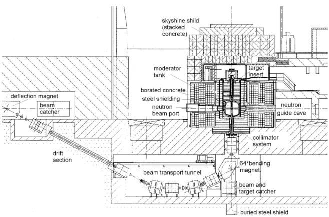
Preparation of the complete design of the target with ancillary systems by taking advantage of the MEGAPIE feasibility study and the existing MEGAPIE design work, and considering the boundary conditions of the SINQ Facility (see figure 1-1).
Definition of critical issues and required R&D needs which are inherent in the design and operation of a spallation target.
- Solution of target specific critical issues in the fields of neutronics, materials, thermal hydraulics, mass and heat transfer, structure mechanics and liquid metal technology, using analytical, numerical and experimental approaches. Selection of best design options according to evaluation criteria established earlier.
- Assessment of safety and reliability aspects which might endanger the integrity and operability of the target; definition and evaluation of countermeasures. Preparation and definition of licensing requirements and criteria.
Figure 1-1 : Vertical cut through of the SINQ facility
The progress of the target design during the MEGAPIE-TEST project can be followed up in previous reports issued in the frame of this project (see Deliverables 08 and 10 and the scientific technological reports). This report summarises the status of the target and ancillary systems design mainly based on the presentations made at the 5th Technical Review Meeting in Nantes, 24-26 May 2004.
In particular:
- The contributions to the general target and ancillary overview were from : F. Gröschel and W. Wagner (PSI).
- The contributions to the target design were from : A. Cadiou, J.S. Stutzmann, T. Kirchner, M. Vatre (CNRS), L. Cachon, G. Laffont (CEA), J.M. Gautier (LPC Caen), S. Dementjev (IPUL). - The contribution to the ancillary design were from : W. Wagner (PSI), G. Corsini (ANSALDO).
2 GENERAL OVERVIEW
The MEGAPIE Initiative has experienced important changes from the administrative and technical point of view since its start and some serious technical challenges have surfaced, which cause additional efforts and have caused some delay according to the original schedule. This might have some consequences on the progress and schedule (delivery dates) of the 5th European Framework Project MEGAPIE–TEST as it is directly linked to the MEGAPIE–Initiative.
Considerable progress, however, has been made in the design and on a number of issues relevant to the design and operation of the target.
2.1 Target Design Overview
2.1.1 Main MEGAPIE target parameters
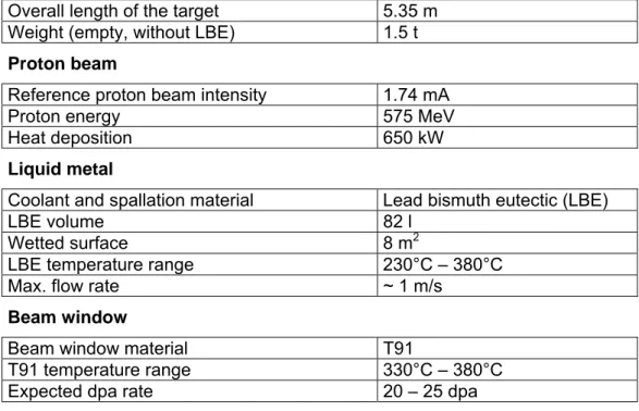
The main MEGAPIE lead bismuth eutectic (LBE) target parameters are summarised in the following table 2-1 :
Target geometry
Overall length of the target 5.35 m
Weight (empty, without LBE) 1.5 t
Proton beam
Reference proton beam intensity 1.74 mA
Proton energy 575 MeV
Heat deposition 650 kW
Liquid metal
Coolant and spallation material Lead bismuth eutectic (LBE)
LBE volume 82 l
Wetted surface 8 m2
LBE temperature range 230°C – 380°C
Max. flow rate ~ 1 m/s
Beam window
Beam window material T91
T91 temperature range 330°C – 380°C
Expected dpa rate 20 – 25 dpa
Tableau 2-1 : Main MEGAPIE target parameters
2.1.2 Brief functional description of the MEGAPIE target
Figure 2-1 shows a schematic view of the different MEGAPIE target sub-systems and the list of ancillary systems.
Figure 2-1 : Schematic view of the MEGAPIE target with its target sub-systems and ancillary systems.
The proton beam penetrates the target via two windows, the double-walled enclosure hull and the inner beam window, from below. The double-walled enclosure hull (Lower Target Enclosure, LTE) is cooled by a forced convection heavy water flow. The inner beam window is cooled by the liquid LBE. The LTE and the beam window are separated by an insulating gap filled with Helium.
The LBE flow is provided by two electromagnetic pumps: an axis-symmetric main flow down an annulus (between Main Flow Guide Tube, MFGT, and Lower Liquid Metal Container, LLMC) and an additional flow via a by-pass tube. Due to the large height of the target, the
character of the flow is mixed convection. The combination of main flow and by-pass flow ensures the cooling of the beam window.
The spallation heat which is produced in the lower part of the MFGT (in the region up to 30 cm above the beam window), is removed via double walled heat exchanger pins to an intermediate cooling loop and finally to an existing secondary cooling system. The fluid of the secondary system is high-pressure heavy water, D20.
In the centre of the MFGT, an instrumentation pin (Central Rod, CR) is inserted which holds instrumentation for the measurement of the neutron flux density and thermo-hydraulic data.
A shielding plug is provided in the top part of the MEGAPIE target, in order to avoid excessive radiation levels in the target head room from direct gamma radiation from the liquid metal.
From the description above the main target sub-systems are:
the double containment composed of a double walled lower target enclosure (LTE made of AlMg3 with a concave sphere shape) and the liquid metal container (LMC) that contains the LBE;
the central rod equipped with heaters, instrumentation and neutron monitors; the 12 pin single walled target heat exchanger;
the electromagnetic pump system, the main pump for the main flow and a second pump for an LBE by-pass flow across the beam window;
the helium insulating gas system; the cover gas system.
2.2 Relevant design issues
The main relevant design issues are focalised :
on the structural integrity of the target in order to keep all active material confined inside the target and this for normal operating conditions and hypothetical accidents;
on performances of the heat exchanger to evacuate the deposited heat; on performances of the electromagnetic pump system;
on the (freezing) properties of the LBE and the behaviour of the spallation products; on the integrity and the cooling of the beam window.
These, and other, relevant issues streamlined the activities performed within the scientific design support. The main items are given in the following list:
neutronic benchmark and a detailed assessment of the nuclear reactions to determine relevant input data for the design and safety assessment of the target;
thermo-hydraulic and thermo-mechanical modelling of the systems and components under normal, transient and accidental conditions, including experimental validation; investigation of material properties under irradiation, corrosion behaviour and the risk of liquid metal embrittlement;
assessment of the LBE properties and the behaviour of the spallation products.
This report summarises the status of the activities developed in the design support and validation task based on the presentations made at the 5th Technical Review Meeting in Nantes, 24-26 May 2004.
2.3 Overview of the Ancillary Systems
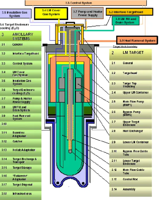
Figure 2-2 shows an isometric view of the ancillary systems necessary for the target operation, as they are planned to be installed, inside the shielding of the SINQ target block.
Figure 2-2 : Isometric view of the MEGAPIE ancillary systems in the TKE, showing the target head in the centre, the intermediate oil cooling loop of the heat removal system at the left, the cover gas system, the fill and drain system and a voluminous steam condenser at the right.
The ancillary systems designed are:
The Heat Removal System, HRS, with Diphyl THT® oil a cooling medium and an intermediate water loop;
The Cover Gas System, CGS, to cope with the overpressure in the target and to assure the confinement of all gases and a regular and controlled venting;
The LBE Fill and Drain System, F&D, with a double containment and an appropriate system for disconnecting the tubes after operation;
The Insulation gas System, IGS
Before the irradiation phase, these systems will be tested in a dedicated test stand (see figure 4-1).
3 TARGET DESIGN (Subtask 1.1)
The design subtask has been based on the MEGAPIE feasibility study and divided into: the Conceptual Design phase:
concentrating on the identification of critical issues, selections of a reference technical design and reference materials, analytical sizing of individual components, definition of instrumentation and operation control, identification of possible sources of failure and consequences, outline design for ancillary systems;
the Engineering Design phase:
concentrating on the numerical optimisation of single components and complete system, identification of component and system failure modes including lifetime expectancy of the system, engineering design of ancillary systems and the preparation of a Quality Assurance Plan for manufacturing and testing
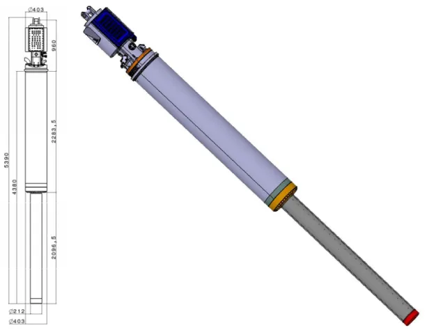
The geometrical boundary conditions and the fact that the MEGAPIE target has to fit to the existing SINQ facility at PSI fixes the main dimensions of the target as shown in figure 3-1. An outer view of the complete target is shown on the right side of the figure.
Figure 3-1 : Main dimensions of the MEGAPIE target and a complete view of the target
The target is composed of: Major structural elements:
Upper Target Enclosure (UTE), Lower Target Enclosure (LTE), Upper Liquid Metal Container (ULC), Lower Liquid Metal Container (LLMC);
Major components:
Target Heat Exchanger (THE), two Electromagnetic Pumps (EMP1 and EMP2), Target Head (TH), Target Top Shielding (TTS), the Central Rod (CR) and the Main and By-pass Flow Guide Tube, LBE leak detector.
For the target components and structural elements, the engineering design phase and the detailed design phase are finished. The detail design calculations and reports are in progress.
3.1 Target
Head
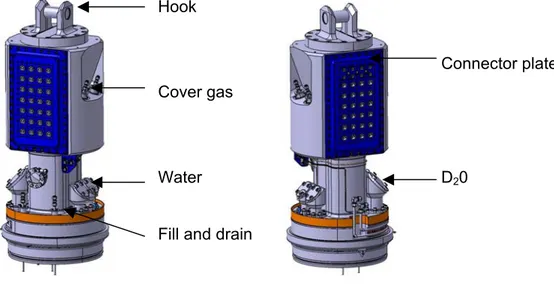
Target Head (TH) is a part of the secondary confinement of the target. It is constituted by a 316 L body, two flanges for electrical connections, one hook, plugs for oil and D2O feeding of the target.
Hook
Cover gas
Water Fill and drain
Connector plate
D20
Figure 3-2 : 3D view of the target head.
A 3 dimensional view of the TH is shown in figure 3-2. The TH assures the interface of the target to the different ancillary systems. All electrical signals and power supplies, pipes and tubes have to pass through the TH. All cables, oil, water and cover gas pipes as well as the fill and drain (F&D) tubes for the LBE have to be designed adequately for an easy disconnection after the target operation. It has to be conform to the safety requirements assuring confinement of radioactive products during all handling steps of the target after irradiation.
The main access ports to the inside of the target are (see figure 3-2):
- The target hook system at the top to insert and extract the target into SINQ. This hook will be manufactured out of a special steel (42CD4) with an optimum mechanical behaviour (At a load of 10 t, corresponding to the maximum weight of the crane in the SINQ hall, the stress is about 143 MPa and the resulting displacement 85µm).
- The Ar cover gas in and outlet with its second containment. - The insulating gas inlet for He at 0.5 bar.
- Two connector plates for electrical cables at the front and backside of the target head. - The oil and heavy water (D2O) in and outlet pipes and the LBE fill and drain tubes.
- The pumping flange (diameter 40 mm) serves to evacuate the target. At the outside of this pumping access, a safety valve will be connected in order to release the overpressure from the insulating gap in case of an accidental LBE – water interaction inside the target.
- Small contact leak detectors are mounted on the top flange in order to detect oil, water of a leak coming from the connectors.
- The tightness of the target with respect to SINQ target guide tube is achieved by a Viton seal at the lower part of the target head. Thermomechanical design calculations showed a strong temperature asymmetry due to the in and outlet temperature (60°C and 200°C respectively) of the heat exchanger oil. To avoid any problems with overheating of the Viton seal a dedicated seal cooling will be tested during the tests phase. According to the results, this cooling system will be mounted or not and might be replaced by a simple air-cooling.
3.2 Target Top Shielding
The Target Top Shielding (TTS) is composed by : two D2O distribution boxes, two DIPHYL distribution boxes, and a set of steel and tungsten massive parts for gamma shielding.
The TTS is the part located just below the target head and covers the space between the TH and the top of the target heat exchanger.
At this level, the oil distribution boxes (for the thermal heat exchanger) and the water distribution boxes (for the lower target enclosure) are located for the in and out-streaming fluids. Due to their particular shape, special attention had to be paid to the stress levels and requested the adaptation of the design. A linear static analysis with the 16 bars design pressure showed that stresses and displacements are within acceptable limits (oil boxes: 117 MPa and 0.18 mm, water boxes: 111 MPa and 5.2mm).
The LBE fill and drain tubes pass at the outside the TTS down to the lower part of the target. The outer tube diameter is Ø 8 mm (wall thickness 1 mm) and both pipes are heated with heaters performing 150 W/m in order to avoid freezing of LBE in the tubes. For monitoring of the temperature the tubes are equipped with two thermocouples.
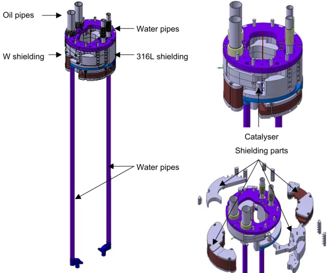
Initially it was foreseen to implement in the TTS gas (Hydrogen) and mercury absorbers. Based on a project decision these absorbers were skipped due to the absence of qualified systems and therefore also for safety and reliability reasons. Hydrogen will be managed together with the other gases produced in the target. For mercury it was decided to implement a catalyser in order to condense the mercury vapours. The catalyser will be mounted on the water boxes in order to be kept at low temperature (see figure 3-3).
Catalyser Shielding parts Oil pipes W shielding Water pipes 316L shielding Water pipes
Figure 3-3 : Target top shielding (left) without (right, lower part) and with the shielding blocks (right, upper part)
The free space in-between these different components has to be filled up with shielding material, in a sort of 3D puzzle. The shielding is a critical issue because of the fact that radioactive material is transported via the liquid metal up to the top of the target (cf. section 5.1.1 Neutronics). In solid targets, the radioactive material is localised in the lower part of the target, in region of the beam interaction with the spallation material. This is not the case for MEGAPIE where radioactive material circulates with the LBE throughout the target. The radioactivity in the target constitutes a source term for the activation of structural material surrounding the target (cf. section 5.1.1 Neutronics). To keep this activation (mainly gamma activation) at the requested levels the shielding
is being optimised. Whenever possible, feeds through this shield should be designed to avoid direct sight.
3.3 Target Heat Exchanger and Upper Liquid Metal Container
The Target Heat Exchanger (THE) is made of 12 pins of 120 cm long arranged in circle. Each pin consists of 2 tubes concentrically arranged: the inlet and outlet tubes. Using the diathermic oil Diphyl THT ® as cooling medium (cf. section 5.4.3LBE-organic oil interaction), it was necessary to implement a spiral in the oil path to increase the contact length. The main problem in the design of the THE was to comply with the complex thermal conditions and to limit the resulting thermo-mechanical stresses. A good agreement has been reached by connecting the pins to the inlet and outlet oil distribution boxes by flexible bellows and by inserting thin shrouds as heat shields. The heat is removed from the THE by an intermediate oil loop designed by Ansaldo. An intermediate water-cooling loop designed and built by PSI then evacuates the heat from the oil loop. The major components of THX are (see figure 3-4):
• Diphyl distribution boxes (DDB), where the distribution of coolant in pins is made, • The pins, which represent the surface exchange to remove the heat of the target,
• The liquid metal enclosure, including the Upper Connecting Flange (UCF), the Upper Lead Bismuth Container (ULMC) and the Lower Connecting Flange (LCF). This set is the upper liquid metal containment of the target.
• The instrumentation, made of thermocouples, is employed to control of efficiency of the THX.
Principal running parameters are : - Flow rate of the LBE: 0.4 l/s; - Diphyl flow rate: 10 l/s;
- Inlet temperature of LBE can be lowered beneath 350°C;
- To avoid liquid metal embrittlement, the minimum surface temperature on the liquid metal side should stay at least about 50°C above the melting point, i.e. above 175°C for the LBE.
The actual THE design can be separated into 3 parts:
- Diphyl distribution boxes that allow the uniform distribution of the oil into the 12 heat exchanger pins. The in and outlet diphyl boxes have to be thermally insulated with respect to the LBE. To reduce thermal stresses, bellows assure the binding between the two tubes of each pin and the diphyl boxes. The shape of the containment wall in
the inlet should be designed to avoid zones of stagnant fluid, where impurities could be collected or bubbles could be trapped.
- The upper liquid metal container assures the bond with the lower liquid metal container. It also has to centre the two electromagnetic pumps and to guide the liquid metal around the pins.
- The heat exchanger pins are constituted of two coaxial tubes. The inside thick tube collects two functions : inflow duct and shielding because of its high thickness.
Figure 3-4 : General view of the Target Heat Exchanger (left) and vertical cutted view (right)
Numerous thermo-mechanical calculations have been performed on the THE design using NASTRAN code. They can be classified in 3 classes according to the following running conditions :
Accidental conditions : this scenario is corresponding to a leak of Diphyl in LBE or a leak of Diphyl out of the liquid metal containment. These calculations are only related to the LBE containment : UCF, ULMC & LCF. They are performed on 1/24 of the total geometry.
Normal steady state thermal conditions, corresponding to the normal operation : Their aim is to demonstrate the efficiency of the thermal insulation of the “Y shape” of the outer tube and the Pin Thermal Insulation.
Normal thermal transient conditions, corresponding to a beam shutdown : these calculations corresponding to the thermal transient situation can be performed separately on :
• the LM container,” duct” area,
Von Mises stresses
Temperature
• the LM container, “web” area,
290MPa 247 MPa247 MPa 259 MPa 290MPa • the pins.
Some fatigue calculations have been required to conclude to the validation of the design of the LMC “duct area” and the LMC “web area” in transient mode, in regard of the expected service life of 10 000 cycles. Calculations according to the fatigue curve at 350°C of 316 L (appendix 1) from RCC-MX [2], give for the pessimistic case, a number of cycle higher than 2.104, higher than the 10 000 cycles required. It must be reminded that the F.E. calculations have been performed assuming pessimistic thermal loads.
The results of these calculations allow to validate the THX updated design. The corrosion effect due to LBE was not taken into account. This device, made of AISI 316 L steel grade, is able to run up to 10 000 cycles in MEGAPIE conditions.
20/73 P&T- FIKW-CT-2001-00159 MEGAPIE – TEST (PU) - D13
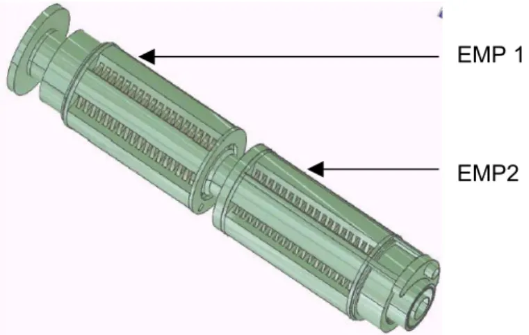
3.4 Electromagnetic Pump System
TO BE CHECKED AND APPROVED BY IPUL AND PSI
Design of MEGAPIE Target electromagnetic pump system (EMP-system) has been developed in collaboration between PSI and Institute of Physics of the University of Latvia. It maintains lead bismuth eutectic (LBE) flow in the target to ensure reliable cooling of beam entrance window.
There are two electromagnetic pumps (main pump, EMP1, and bypass pump, EMP2) to transport LBE and two flow meters (one in main flow and one in the bypass flow).
The main pump is responsible for a transit flow between the LBE container and heat exchanger elements mounted on the periphery of the target.
The by-pass pump is responsible for a flow through the special nozzle situated radial in the container to destroy the flow symmetry (see figure 3-5). The EMPS is mounted in steel housing to protect it from LBE.
EMP 1
EMP2
Figure 3-5 : View of the electromagnetic pump system
Main characteristics are: For the mainstream pump:
Straight through pump with upward flow; Nominal flow rate for LBE: 5 L/s;
Nominal operating LBE temperature range 180 0C to 400 0C;
Maximal operating temperature of EMP coils: 450 0C;
Pressure drop in the outer loop: 0,2 bars. For the bypass pump:
Straight through pump with upward flow and redirection downwards in the bypass tube; Nominal flow rate for LBE: 0,5 L/s;
Nominal operating LBE temperature range 180 0C to 300 0C;
Maximal operating temperature of EMP coils: 4500C;
Pressure drop in the outer loop: 0,5 bars at 0,5 L/s.
One of structural features of EMP and flow meters design and production is the fact, that products are not serial production and each time there is a need for choosing and fabrication of special equipment and tooling: tooling for assembling of magnetic yokes, of coils, of stamps for cutting slots into steel sheets and other. The consequence of operations at EMP-system production is following:
1. Production of tooling;
2. Cutting of the sheets for magnetic cores and yokes of pumps; 3. Cutting out slots in magnetic yokes;
4. Production of coils;
5. Production of the details of the channels of pumps; 6. Assembling of magnetic yokes and cores;
7. Annealing of the cores;
8. Production, tests and graduation of flow meters;
9. Assembling of by-pass pump including its fixing at lower flange; 10. Assembling of the main pump;
11. Assembling of joint for pumps and flow meters; 12. Assembling of ampoule;
13. Annealing of ampoule;
14. Checking and tests of assembled EMP-system.
The main constructive data and characteristics of pumps for EMP-system at nominal regimes are shown in the following tables:
Taking into account rather hard conditions of operation excluding any possibility for repair and change of separate parts the documentation and construction of EMP-system must correspond to the Detailed Design and Quality Insurance Rules. Any changes or deviations from Detailed Design must be approved by MEGAPIE Project Management.
The following procedures for manufacturing and assembly are foreseen: 1. To carry out initial tests of materials used for construction of system.
2. To design and to manufacture the machining auxiliary attachments for fabrication of details and parts of construction.
3. To manufacture the inner element of the channel of EMP1 applying annealing of the core (tubes 62 x 2 mm and 92 x 1.5 mm).
4. To fabricate the outer element of the channel of EMP1 (using X-ray tests for the strength and leak-proofness), and the core of EMP2 (tubes 106 x 2 mm and 125 x 1.5 mm).
5. To fabricate the yokes for EMP1 and EMP2.
6. To fabricate the inductors for EMP1 and EMP2 (with boring orifices for the channel, _ 126 mm and _149 mm).
7. To fabricate the coils for EMP1 and EMP2 applying impregnation, drying and baking. 8. To assemble the inductor of EMP1 with coils, to solder the outputs according to the scheme, to make impregnation and drying to insure electrical isolation.
9. To assemble the inductor of EMP2 with coils, to solder the outputs according to the scheme, to make impregnation and drying to insure electrical isolation.
10. To fabricate the inner element of the channel of EMP 2 (using X-ray tests for the strength and leak-proofness), tubes 135 x 1.5 mm and 112 x 1.5 mm).
11. To fabricate the outer element of the channel of EMP 2, tubes 148 x 1.5 mm and 125 x 1.5 mm).
12. To fabricate the elements of by-pass decoupling tract. 13. To fabricate the flow meters for EMP 1 and EMP 2.
14. To fabricate the EMP 2 (the channel with by-pass, inductor and flow meter) in full assembly.
15. To assemble the inductor of EMP 1 with flow meter. 16. To assemble EMP 1 and EMP 2 on the channel of EMP 1.
17. To install the assembly into the outer housing (tube 232 x 2 mm), to compound the air cavities, to dry the compound, to fix and to weld necessary welds.
18. To carry tests for strength and leak-proofness.
19. To make the milling of base surface to be perpendicular to the housing surface.
20. To assembly the EMP-system applying leak-proof spacers, to attach the joint flange and to carryout the tests for leak-proofness.
As during the operation of EMP-system it will be exposed to thermal and mechanical loads, and also to action of liquid metal heat transfer medium, all parts of ampoule must be checked and tested in accordance with standard demands.
The tests are foreseen to carry using 4 methods: 1. All butt welds to test using X-ray tests. 2. Edge welds to test using Dye-penetrating method. 3. Bulk cylindrical elements to block and to test using corresponding gas pressure. 4. To carry out leakage-proofness using He-leakage method.
Special attention must be given to the elements having the contact with liquid metal. It is to the channel of main pump with the core, the channel of by-pass pump and housing. Leakage and even micro cracks may lead to short circuiting of pumps windings, of core plates and as a result to damage of all EMP-system.
So the channel of by-pass will be divided into parts and will be tested separately according to mentioned methods:
– inner part of the channel; – outer part;
– lower collector together with tubes; – after welding tubes with upper collector; – then all assembly.
In the same way also the channel of the main pump will be tested separately.
- inner part of channel with core - outer part
- assembled channel.
And at last fully assembled ampoule will be tested: - to test joint elements of housing and pump assembly - to test under pressure the channels of the pumps
- to test the strength of outer housing by gas pressure (10 bar) - assembled ampoule will be tested using He-leakage method.
Electrical resistance will be checked between phases of power supplying cables and housing, short-circuiting of coils, Q-meters and workability of thermocouples. For each tests and checks corresponding protocols and acts will be prepared.
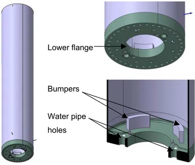
3.5 Upper Target Enclosure
Compared to the other target components the Upper Target Enclosure (UTE) is a simple cylinder made out of stainless steel A316L, with connecting flanges (see figure 3-6). The lower part is connected to the lower target enclosure. No particular cooling is foreseen for the upper target enclosure.
Lower flange
Bumpers Water pipe holes
Figure 3-6 : Views of the Upper Target Enclosure
3.6 Lower Liquid Metal Container
The Lower Liquid Metal Container (LLMC) is a part of the primary confinement. It is constituted by a shell with thickness varying from 4 to 1.5 mm and an interface flange with the Main Flow Guide Tube (MFGT).
The LLMC is one of the critical structural parts of the MEGAPIE target. In particular the beam window is exposed to severe constraints: proton and neutron irradiation, thermal and mechanical load and the presence of flowing LBE. The structural material for the target container is martensitic (French designation T91 type) steel ( cf. section 5.2.3 State-of-the-art on the T91 steel characterisation under MEGAPIE relevant conditions). For the Upper Liquid Metal Container (see above) the use of austenitic (316L type) steel is considered, which is more readily available and easier to weld. This is contingent upon sufficiently high liquid metal corrosion resistance, because the highest temperature gradient in the system will occur along the heat exchanger. In order to facilitate the transition between two different materials the two parts will be joined by a flange system.
Figure 3-7 shows the LLMC with a zoom on the beam window region (right). For buckling reasons the thickness of the cylindrical part is 2 mm in the lower part and 4 mm in the upper part.
Figure 3-7 : The lower liquid metal container (left) showing a cut through the 1.5 mm thick beam window (right).
LBE leaks out of the liquid metal container into the gap filled with helium must be detected very rapidly. Dedicated leak detectors are under investigation that allow to detect very small quantities of LBE. One solution is strip detectors fixed to the liquid metal container and
thermocouples. A system of springs maintains the strip detector on the inner part of the lower target enclosure.
Investigations are ongoing for this LBE leak detectors. The feasibility of such a procedure is currently being assessed.
3.7 Lower Target Enclosure
The whole target container will be surrounded by a second enclosure, the Lower Target Enclosure (LTE), with helium gas in-between. In the lower part this enclosure will be double walled with heavy water cooling as is the present target shell ( cf. section 5.4.2 LBE-water interaction). The material for this part will be chosen for minimum neutron absorption and sufficient strength at any temperature the shell might reach in the case of a breach of the target container. Presently, Aluminium (AlMg3) is the favoured material, the same as for the actual solid SINQ targets.
The reversed spherical shape of the LTE (see figure 3-8) has been adopted because it allows the LBE in case of a leak to flow into the lower edges of the LTE. This avoids accumulation of LBE in the centre where the beam hits the target. Remaining LBE in the beam interaction zone would lead to a strong power deposition and could provoke the rupture of the aluminium double walled shell. Upper flange Double walled enclosure LLMC & LTE Catcher
Figure 3-8: The lower target enclosure (left) showing a vertical cut (right) through the upper flange and the double walled enclosure
3.8 Main Flow Guide Tube
The Main Flow Guide Tube (MFGT) separates the down-coming cooled LBE on the outside from the up-streaming hot LBE in the inside. Main components (see figure 3-9) are the MFGT itself, made out of A316L stainless steel, the interface flange, for the electromagnetic pump and three spacers to keep the components in the defined position in hot as well as in cold conditions. A zoom on the lower part of the MFGT shows the by-pass tube for the additional window cooling, the fill and drain tubes and thermocouples for the temperature measurement in the lower part of the target.
The final shape of the by-pass tube outlet, the length of the fill and drain tubes as well as the position of the thermocouples are not yet finally fixed. Their final design will depend on results of thermo-hydraulic calculations performed by the MEGAPIE scientific design support and also results of experiments performed at FZK with PSI support (Heated Jet and KILOPIE LBE experiments and HYTAS water experiment).
EMP interface flange
THE interface flange
Main flow guide tube
Spacers LBE fill and drain tubes Bypass flow guide tube Thermocouples
Figure 3-9 : Views of the main and bypass flow guide tubes
3.9 Central
Rod
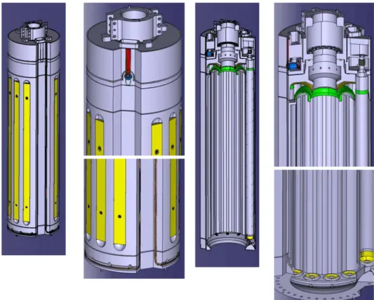
The Central Rod (see figure 3-10) will be inserted from the top into the MEGAPIE target. The CR fills up the central part of the target and reduces the amount of LBE. It is equipped with two heaters for the heating up of the target prior to the filling in of the LBE and to avoid uncontrolled freezing during operation when the beam is off. Neutron detectors will be install (small fission chambers designed by CEA) in the bottom part inside the CR to measure the thermal and fast neutron fluency. External diameter : 57.5 mm Internal diameter : 15 mm Heater External Diameter: 25 mm Internal diameter : 13 mm 316L shielding Location of the neutron detectors
Figure 3-10 : The central rod (left), zoom of the upper and lower part (middle), cuts through the central rod (right)
3.10 Manufacturing
The detailed design of the target is finished and the manufacturing phase is started. The main institutes involved in the design are CNRS/IN2P3/SUBATECH, PSI and CEA for the Heat Exchanger.
After an international Call for Tender, ATEA has been chosen. ATEA is a member of REEL group and localised in Carquefou (France).
A step by step approach is used to manufacture the target, based on the different Lots: Lot 1: Upper Target Enclosure
Lot 2: Lower Target Enclosure Lot 3: Target Head
Lot 4: Target Top Shielding
Lot 5: Heat Exchanger & Upper Liquid Metal Container Lot 6: Lower Liquid Metal Container
Lot 7: Main & By-pass Flow Guide Tube Lot 8: Central Rod
Lot 9: Assembly
The procedure applied for each Lot is to perform a Detailed Design Review and a Readiness for Manufacturing Meeting before starting the manufacturing process (machining, welding, assembling).
Detailed Design Review try to determine if a Lot is sufficiently defined to be manufactured. The main task is the verification of the drawings, engineering and design documents. For all target sub-systems, manufacturing drawings were performed and discussed in detail with colleagues from PSI. Step by step open design issues were solved and integrated in the drawings to come up with a final set of drawings for the manufacturer. A series of design calculations were performed to backup the target design.
The manufacturer checks all drawings and all open points (design and feasibility) will be discussed in detail with the manufacturer. Manufacturing will than start after dedicated Readiness for Manufacturing Meetings.
Readiness for Manufacturing Meeting evaluates systematically one set of documents to perform the manufacturing, assembly and test process signed by the PSI. Main documents to perform the RfM review are: general specifications, particular quality assurance program, drawing set, detailed specifications, engineering and design documents, manufacturing and sub-assembly plan, test inspection plan, schedule, cost update.
Then, manufacturing sequence for each Lot can be summarised as follow: process definition (technology, tools, qualifications), procurement of material and instrumentation, machining, assembling procedure, pressure test.
After three years in the framework of the MEGAPIE-TEST WP1, each sub-system of the target is released after a Readiness for Manufacturing Meeting. All pieces are machined. Welding and assembling phases are started. According to the manufacturing planning, the delivery date for the target is foreseen for the end of April 2005.
4 ANCILLARY SYSTEMS DESIGN (Subtask 1.1)
The MEGAPIE target, operating with liquid Lead-Bismuth-Eutectic (LBE), requires a number of ancillary systems to be fit for operation. These can be grouped in three categories:
The operational ancillary systems, i.e. those which are immediately necessary for the target operation. These are the heat removal system (HRS) to extract the heat deposited in the liquid metal by the proton beam, the cover gas system (CGS) to handle the gases and volatiles produced during the spallation reaction, the insulation gas system (IGS) which guaranties the presence of insulating gas between the safety hull and the liquid metal container, and the fill and drain system (F&D) for filling the target with liquid LBE, all systems together with a common control system.
Others are implemented into the beam line serving two purposes: i.) the visualization system VIMOS and the beam-canalising slit in QHJ30, both independently to prevent fatal accidents by unintentional loss of beam scattering in target E, and ii.) a new LBE catcher and guiding funnels to minimize the consequences of accidental spilling of liquid LBE into the proton beam line.
A third category serving the target handling, transport, dismantling and disposal, which includes activities at ZWILAG and at the PSI hotlab.
Special attention has to be paid on the Fill-and-Drain System, the Cover-Gas System and the Insulating Gas System, in particular with respect to the required interfaces and double enclosure concept, the latter to some extend also affecting the target head interface. Directly related to the target heat exchanger is the heat removal system as one of the main ancillary systems. The arrangement of the systems in the TKE is now well elaborated (see figure 2-2). Regarding the beam line adaptation, there are still ongoing considerations for a special beam collimator to prevent a focussed beam from hitting the target, in conjunction with the VIMOS system for visualizing possible beam focussing. A further important task, the hotlab adaptation, has finished its feasibility study in collaboration with the hotlab operation division.
4.1 Liquid Metal Cover Gas System
The Target Cover Gas System (CGS) is located near the northeast corner of the TKE, connected to a ‘Small Box’ positioned close to the target head. The CGS system is currently in the detailed design phase. The main component parts of the CGS are a relatively large-volume decay tank, a vacuum pump and interconnecting tubing fitted with 6 solenoid valves for remote operation in the main box, and 4 in the small box. As the CGS is containing to a large extend radioactive
gases all components of the system have to be confined in a secondary containment to prevent any release into the TKE.
Extraction of cover gas will be necessary whenever the pressure increase due to the gases produced in Pb-Bi by spallation will reach a defined pressure, max. 0.2 MPa. The functions of the cover gas system are:
- to extract periodically these gases, to restore the start pressure (0.02 MPa). - to let the radioactivity of volatiles (mainly noble gases) decay
- and to emit the remaining gas through an aerosol and active carbon filter into the controlled air exhaust of the accelerator plant when its airborne radioactivity is well below the allowed limits.
Vapours of volatile elements - mainly Hg and Po - are adsorbed within the expansion tank. The production rate of hydrogen isotopes and He determines the frequency of extractions, expected to be typically once per 1-2 months. This periods result from R&D support on neutronic/nuclear calculations done at PSI, LANL, CNRS … to be checked/confirmed by ISOLDE experiments which will give more information on the spallation product production.
Gases shall be extracted by the cover gas system only during beam-downs. The gas is cooled from approximately 240 C to 50 C by streaming slowly through the cold trap built inside the upper target shielding, where the main part of remaining vapours condense. The decay tank stays always at under-pressure. Gas samples can be taken for radioactivity checks before each main action.
In spring 2004, the CGS received its final design updates and interface definitions, after re-assessment of expected and tolerable radiation levels in TKE and confirmation of the necessary shielding in TKE around the decay tank, valves and pipes. In this course, a simplified sampling procedure with unshielded sampling device was defined and approved, using a glass phial and a needle to perforate the covering membrane. The procedure defines sampling of fresh cover gas after a short target irradiation period with defined maximum charge received, and regular (or occasional) sampling of decayed gas before venting. Furthermore, the pressure transmitters (Kistler), vital components of the CGS to control the plenum gas pressure and quantify the sampling and venting inventory, were qualified for radiation resistance up to a total Gamma-dose of 1 MGy. They were found to resist this dose in a dry state, without a silicon oil buffer. The silicon oil showed degradation by gas release and was found not suited for high-dose applications.
4.2 Insulating
Gas
System
The IGS fills the volume between the lower liquid metal container and the double-walled safety hull by an insulating gas. The initial concept of a filling with Ar was changed in favour of a filling with He at a pressure of 0.5 bar, benefiting from lower activation on the expense of a higher heat leakage through He. The expected heat leakage of about 20 kW can readily be handled after filling the target with liquid LBE but would hamper the preheating before filling. Therefore during preheating a temporarily Ar-filling will be necessary.
The IGS was engineered at PSI, the P&ID scheme, signal lists and specification of components are finished. The final design update will be done after the completion of the HRS commissioning. One of the accident scenarios that needed to be looked at was water ingress from a leaking safety hull into the insulation gas volume with the consequence of steam production and possible pressure built-up. According to calculations the consequences of such an event can well be handled by a 40 mm diameter exhaust pipe and a steam condenser vessel outside the insulation volume.
The system has to assure the following functionality:
- Surveillance of integrity of the confinement (leak detection into the insulating gap); - Evacuation of D2O vapour in case of a leak into the insulating gap;
The selection of He gas system (He at 0.05MPa in normal operation) is based on the following arguments :
- The gas must be chemically inert;
- He is better than Ar due to its lower specific activation;
The system is composed of the gas filling tubes and the evacuation tube equipped with a certain number of valves. The evacuation of the insulating gas goes via the steam condenser vessel to the controlled exhaust system.
4.3 Liquid Metal Fill & Drain System
The liquid metal Fill & Drain System (F&D) of Megapie is intended to provide:
- frequent filling and draining of the target with LBE at the integral test stand (MITS), - the initial filling of the target with LBE at the irradiation position in TKE,
Following the initial baseline, a design was elaborated for the F&D system which had allowed to drain activated LBE. However, the manipulation of the irradiated LBE was recognised to be a very critical and risky operation and very demanding on terms of safety. Particularly the following items had to be addressed:
- Pipe plugging (to be prevented during the phase of final or intermediate LBE draining). - Final squeezing and cutting of pipes for the remote disconnection (separation of the
drain vessel from the other parts of the system). This double operation has to assure that there will be no release of LBE and contaminated gas out of the tubes.
- Valve failure;
- Recristallisation: The volume increase after freezing represents one of the main drawbacks of LBE. The volume increase can turn into stresses of the container walls and of its internals.
- Seal filling by fresh LBE: The final sealing of the vessel containing the irradiated LBE is performed, in order to assure a sufficient radiation shield, by pouring on the free level of the frozen irradiated LBE a layer (100 mm) of un-irradiated LBE.
- Overall functionality must be guaranteed by a series of tests performed at the nominal operating conditions following the complete F&D procedure, except for the final cutting. An additional major issue in conjunction with active draining was the double containment of the F&D system. The Polonium concentration in the contaminated LBE is such that the vapour emission and sputtering that will condense on the surrounding surfaces will produce a contamination beyond the limits. Even if the design of radioactive containment and manufacture has been made with the higher standard, for safety reason one has to assume that a failure may happen producing a leakage. Therefore the parts of the system containing activated LBE (like the CGS as mentioned above) must be enclosed in a secondary containment that prevents any spill into the TKE in case of an LBE leak. The secondary containment must assure early leak detection out of the primary containment wall, the collection and containment of the leaked matter so that extraordinary provisions can be made to restore a safe situation inside the TKE. The secondary containment has an impact on the operation required when equipment and components have to be disconnected for independent handling and transportation.
Viewing these considerations the concept of active draining was abandoned in favour of only inactive draining and final freezing of the LBE in the target after completion of the irradiation experiment.
This design amendment allowed several significant simplifications for the F&D system: No need for approved radiation-hard components, no need for a second containment, no device for crimping and cutting of pipes contaminated by irradiated LBE. On the other hand, the inherent final freezing implements mechanical stressing of the hull and window material due to the well-known volume expansion of solidified LBE. Hence, post-irradiation adulterations of the materials properties are possible. This drawback is intended to be minimized by controlled freezing and crush zones implemented in the lower target volume.
Figure 4-1 : The MITS at PSI in March 2004: The oil loop in place at the right hand corner of the platform (thermally insulated, but still uncovered), the WCL underneath, and the racks of the control system in the rear. A wooden plate covers the target reception flange in the middle of the MITS.
For operating the F&D system at the MITS (see figure 4-1), besides the regular draining vessel positioned above the target head a second draining vessel located underneath the target is necessary, primarily for emergency draining by gravitation, but also for ease of frequent regular draining on the test stand. This part of the F&D system will not be transferred to the TKE; there only the upper vessel with the necessary piping and gas supply can be used.
4.4 Heat Removal System
The Heat Removal System (HRS) of Megapie is designed to transfer heat from the target heat exchanger (THX) and dissipate it to the cooling water circuit via the intermediate heat exchanger (IHX). The target heat removal will be effected by means of an organic coolant Diphyl THT, Bayer.
The HRS consists of two subsystems: an intermediate cooling loop (ICL) with oil Diphyl THT as cooling medium, connected to the heat exchanger pins in the target. The ICL is back-cooled by a secondary water-cooling loop (WCL). The oil loop, operating between 160oC and 230oC (the LBE temperature in the target varies between 230oC and 330oC) is primarily necessary to remove the about 0.6 Megawatt of heat load deposited in the liquid LBE by the proton beam. As
a second function it must also be capable to manage a controlled hot-standby operation after beam trips or scheduled beam interruptions to prevent freezing of the target. Unintended freezing would be fatal because solid LBE is known to expand after solidification by an enduring phase transformation which would stress the LBE container and thus inhibit a continuation of the experiment.
The main functions performed by the HRS are:
- LBE cooling during normal beam operation, by removal of heat from the LBE coolant; - Control of the LBE temperature, on the cold leg, during normal beam operation, beam trips
and extended shutdown phases;
- Provide a barrier to prevent any release to the environment of radioactive isotopes from the LBE circuit;
- Confine any ingress of radioactive isotopes from LBE side, further to accidental rupture of THX pins;
- THX heating up, to accept LBE filling;
- Minimise the frequency of conveying to the gas venting system the gases formed in the diathermic fluid as a consequence of radiolysis and pyrolysis;
- Monitor and collect small leakages of the diathermic fluid from any point of the HRS.
Power transients, which are caused by the relatively frequent proton beam trips or interrupts, require a control system that enables one to keep the target temperature variations within acceptable limits. First simulation results show that the temperatures can be maintained sufficiently far above the melting temperature of Pb-Bi.
The main arguments for the selection of the organic coolant for the intermediate cooling circuit of MEGAPIE are
- low vapour pressure (3mbar at 158°C)
- satisfactory heat transfer capability (0.15 kJ/(kg*K) for LBE at 300°C)
- tolerable decomposition and irradiation effects under the operating conditions
Based on a certain number of irradiation experiments (sealed capsule in a TRIGA reactor, electron irradiation experiment, analysis of early experiments under reactor conditions) extrapolations of the data to MEGAPIE conditions were performed with the conclusion that the max. decomposition of THT (23wt%) would be of no concern for risk of fouling. The radiolysis is likely to be half that figure.
4.5 New Safety Devices in the Beam Line
Three new devices are foreseen in the beam line for safeguarding MEGAPIE against perforation of the target by an insufficiently scattered proton beam; these are VIMOS, a slit in QHJ30, and upgraded current monitors at Target E. Each of these novel or upgraded systems on its own should be capable of switching off a narrow incident beam before any damage is done to the liquid metal target. Two of the systems have already been installed during the latest shut down at the beginning of 2004. First test results have proven the principal working of these devices.
4.5.1 VIMOS
The actual beam at the SINQ target will cause the glowing foil in the VIMOS hat to emit IR and visible light accurately tracing the incident intensity distribution.
Experiments in a dedicated mock-up facility had yielded the following characteristics for VIMOS:
- Observable area on glowing foil: ~ 10 x 11 cm - Resolution: ~ 1 mm
- Depth of field: ~ 1 mm @ focus and ~ 50 mm @ target - Minimum detectable temperature of glowing foil: ~ 900 oC
These values have been confirmed under the real conditions in the beam line.
4.5.2 Slit KNHY30 in QHJ30
The slit KHNY30 in the quadrupole magnet QHJ30 takes advantage of the fact that scattered protons take a slightly different path compared to non-scattered protons due to their different energy / momentum. The largest separation of about 20 mm between the centres of these two fractions of the beam occurs inside QHJ30. Two initially adjustable jaws will be aligned and locked such that only correctly scattered protons can continue to the SINQ target whereas the lower jaw of the slit will block particles with too high energy.
Already shortly after switch-on of the accelerator first tests have been performed to position the copper jaws. As soon as the slit was positioned first sensitivity checks were performed by slightly changing the trajectory of the protons before Target E. This led to an immediate increase in the readings of the ionization gauge MHI37 downstream of the slit and it also produced a jump in the detected charge on the lower jaw. With appropriately selected thresholds both signals very reliably trigger an interlock.
4.5.3 Catcher and Funnels
A new LBE catcher and guiding funnels to minimize the consequences of accidental spilling of liquid LBE into the proton beam line are designed and manufactured, and have been installed and tested in-place during the latest accelerator shutdown in Spring 2004.
4.6 Target Handling: Concept for Transport and Dismantling
The actual concept for transport and dismantling of the irradiated MEGAPIE target – which is to be confirmed in a more detailed study and which requiring official licensing in several steps – is to transfer the target to the hot cell at ZWILAG in a specially build container, after a certain cooling time in the SINQ target storage. After visual inspections and dimensional measurements on the LMC in the hot cell, the Target will be cut into pieces und packed into a shielded transport container (PSI RA-waste container KC-T30). The container will be transferred to the hot cell at hotlab in order to remove the LBE from the target pieces and extract samples for the PIE investigations.
Later the same container can be used for the interim storage at PSI (location has not been defined) and for the final storage of the conditioned target. At this time the activity will be low enough to remove the steel cladding, remaining a normal licensed KC-T30 container.
5 DESIGN SUPPORT AND VALIDATION (Task 1.2)
5.1 Neutronics
5.1.1 Summary of the past activities in the neutronic and nuclear assessment
This section describes briefly the past main achievements in the neutronic and nuclear assessment, relevant for the design of MEGAPIE. All the important aspects relevant to neutronic performance, power deposition, radiation damage, isotope production, and radioprotection issues were treated. References are given where these results are discussed in detail. In sections 5.1.2 and 5.1.3, the most recent achievements are described.
Target performance
Proton and neutron fluxes in the MEGAPIE target have been calculated. Detailed MCNPX models have been developed of the SINQ facility with the Mark 3 target and calculations were performed for this and the MEGAPIE target. A comparison between the neutron flux with MEGAPIE and the SINQ solid target was made in Ref. [1]. Results showed that the MEGAPIE target will deliver 40% to 50% more neutrons to the instruments served by SINQ as compared to the Mark 3 target.
Power deposition in the target
Calculations of the beam power deposition distributions are essential for the thermohydraulics CFD analysis of the lower target. Power deposition was calculated using the codes FLUKA and MCNPX [2,3]. The results from the two codes agree within 5%.
Approximately 85% of the beam power is dissipated in the target-moderator system (71% in the lead-bismuth), the rest is dissipated in the surrounding shielding.
The power deposition in the lead/bismuth eutectic (LBE) was studied in detail. It was found that the power deposition could be described by an analytical function such as [4]:
(
x
y
z
)
G
( ) (
z
D
x
y
z
)
P
d,
,
=
,
,
where G(z) describes the longitudinal distribution of the peak of the power deposition, for x=y=0;
D(x,y,z) is fitting the evolution of the axial component of the power deposition. This term has a
Gaussian dependence on x,y, with a σ with a quadratic dependence on z.
Beam power deposition on the structural materials was also calculated. About 2% of the beam power is dissipated in the T91 lower liquid metal container and in the AlMg3 lower target enclosure. Considering the average between the results from FLUKA and MCNPX, the peak power deposition is 900 W/cm3 in the T91, and 315 W/cm3 in the AlMg3.
Results from the thermohydraulics calculations using the neutronic results as input are in Ref. [4].
Radiation damage to structural materials and dyphil oil
Detailed neutronic calculations were performed using a measured beam profile [5]. Radiation damage in the T91 window and in the safety hull, using the damage cross sections from Ref. [6] and helium production were calculated [3]. From these calculations it can be derived that the peak damage and helium production rates at the beam window are 2.6 dpa/A·h and 215 appm He/A·h, respectively. In the centre, the proton contribution to dpa is as important as the neutron one. As far as the distance from the centre increases, the neutron contribution becomes dominant. These results have been used in Ref. [7] in the frame of a research work to assess the lifetime of the target.
A neutronic analysis of the dose rate to the THT oil, the working fluid in the secondary loop of the MEGAPIE Pb-Bi cooling system, was performed [8]. The dose received by the oil is dominated by the activated LBE. For the 77-Kg inventory of oil in the secondary loop, the absorbed dose is 0.2 W·h/g after 6 A·h of operation.
Isotope production in the target
This field of research has received a lot of attention in recent years, mainly because of the research in the ADS (see for instance the HYNDAS program) and more research is in progress. In the case of MEGAPIE, it is important to evaluate the radioisotope inventory for safety reasons. Moreover, the amount of gas produced (especially H and He) is important for the gas handling procedure.
The precision in the numerical estimates of the nuclide production is limited by the models used and by the nuclear data libraries available. The strategy adopted consisted in a code intercomparison [2,9,10], followed by a comparison with experimental data. This work is still in progress as new experiments are being carried out.
We discuss here the comparison between FLUKA and MCNPX. Overall there is a good agreement between the calculations; concerning the individual isotopes, for which the production rate is higher, for the ones close to the mass of the target, in general agreement within a factor of 2 or better is found. This result is important since Hg and Po are the most important elements as far as radioprotection is concerned. However, for other isotopes, and especially for the lighter elements, because of the different spallation/fission models used, and the different libraries for interaction of neutrons with the target material, larger differences are found.
In Ref. [2] a first attempt to evaluate the uncertainty of the FLUKA predictions was performed, based on the comparison between measured residual products at different proton energies. Calculations were compared with the data from Ref. [11]. In general, the ratio between data and calculations is about a factor 2-3 in the spallation region, and almost a factor of 10 in the fission region.