HAL Id: hal-02338456
https://hal.telecom-paris.fr/hal-02338456
Submitted on 26 Nov 2019
HAL is a multi-disciplinary open access
archive for the deposit and dissemination of
sci-entific research documents, whether they are
pub-lished or not. The documents may come from
teaching and research institutions in France or
abroad, or from public or private research centers.
L’archive ouverte pluridisciplinaire HAL, est
destinée au dépôt et à la diffusion de documents
scientifiques de niveau recherche, publiés ou non,
émanant des établissements d’enseignement et de
recherche français ou étrangers, des laboratoires
publics ou privés.
Precise Spatio-Temporal Electromagnetic Fault
Injections on Data Transfers
Alexandre Menu, Shivam Bhasin, Jean-Max Dutertre, Jean-Baptiste Rigaud,
Jean-Luc Danger
To cite this version:
Alexandre Menu, Shivam Bhasin, Jean-Max Dutertre, Jean-Baptiste Rigaud, Jean-Luc Danger.
Pre-cise Spatio-Temporal Electromagnetic Fault Injections on Data Transfers. 2019 Workshop on Fault
Diagnosis and Tolerance in Cryptography (FDTC), Aug 2019, Atlanta, United States.
pp.1-8,
�10.1109/FDTC.2019.00009�. �hal-02338456�
Precise Spatio-Temporal Electromagnetic Fault Injections on Data Transfers
Alexandre Menu∗†, Shivam Bhasin†, Jean-Max Dutertre∗, Jean-Baptiste Rigaud∗, Jean-Luc Danger‡
∗Mines Saint-Etienne, CEA-Tech, Centre CMP, F - 13541 Gardanne France {alexandre.menu, dutertre, rigaud}@emse.fr
† Temasek Laboratories, Nanyang technological University, Singapore [email protected]
‡LTCI, Télécom ParisTech , Institut Mines-télécom, Université Paris Saclay, 75634 Paris Cedex 13, France [email protected]
Abstract—Fault injection techniques allow an attacker to alter the behavior of an electronic device in order to extract confidential information or be granted unauthorized privileges. To this end, local electromagnetic fault injections (EMFI) are commonly used to corrupt or prevent the execution of instructions.
However, little attention is devoted to practical data corrup-tion. This article investigates the local effects of EMFI on data transfer from the Flash memory to the 128-bit data buffer of a cortex-M microcontroller. We demonstrate that the corrupted bits are closely related to the location of the injection probe, allowing us to set or reset from 0 to 128 bits with a byte-level precision. Moreover, the spatial and temporal accuracy of the injection technique allowed us to target the data prefetch mechanism without corrupting the code execution.
We highlight the efficiency of the derived fault model with three practical case studies. Firstly, we demonstrate precise key-zeroing and key-setting capability, with further extension to a DFA on the secret key of a cipher from Biham and Shamir, that was never implemented practically. Next, we report practical persistent faults on ARM microcontroller, which allows an attacker to retrieve the secret key of a cipher with a single successful injection.
Keywords-Fault attack; Electromagnetic injection; Data transfer; Flash memory; Persistent fault; DFA; 32-bit micro-controller
I. INTRODUCTION
Side-channel attacks exploit the physical implementation of electronic devices to extract confidential data. These attacks are divided into two main categories: passive side-channel analysis and active fault injection. The former are based on the collection of side-channel emissions to extract information, while the latter takes advantage of a physical stress to alter the functional behavior of an electronic circuit. In 2001, Boneh et al. introduced fault attack, a cryptanalysis technique which exploits the erroneous computations of an electronic device to retrieve the secret key of a cipher [1]. Since then, an extensive litterature discusses practical fault models and efficient implementations of countermeasures against fault injection.
The first non-invasive fault attack based on electromagnetic pulse was reported by Schmidt et al. in 2007 [2]. Despite
the growing interest of the fault attack community for the electromagnetic side-channel, a consistent decription of the physical fault mechanism remains out of reach. However, previous work highlighted the interactions between an injection probe and the clock tree [3], reset line [4] and power-ground network of a device [5]. These concurrent phenomenons partially explain the plethora of fault models reported in the litterature on electromagnetic pulse injection. While both instruction and data corruption are commonly observed, instruction corruption, and especially instruction skip, is considered as the most practical fault model [6].
In this paper, we demonstrate critical vulnerabilities that do not rely on instruction corruption. We provide an in-depth charaterization of faults induced on data while being transferred from the Flash memory to the register file of an ARM Cortex-M microcontroller. Unlike previous works, we also demonstrate the exploitability of these fault models in practical case studies. As shown later, we realize some extremely complex faults as byte-wise key zeroing or persistent faults, which are not practical with instruction corruption. As a result, some attacks requiring high attacker expertise can be performed, including the original DFA of Biham and Shamir on the key transfer of an unknown cipher, which was never shown to be practical to the best of our knowledge. All the case studies are performed on the public AES implementation from Stofflen and Schwabe [7].
The outline of this article is as follows. The state of the art on electromagnetic pulse injection is summarized in Section II. Our experimental setup and methodology are detailed in Section III. Observed fault models on data transfer and their relationship to EM injection parameters are described in Section IV. Three practical attacks based on our characterization results are described in Section V. Section VI concludes this article.
II. RELATED WORK
While a substantial litterature address instruction corrup-tion, only few works characterize or exploit data corruption. Previous work highlighted that EMFI allows an attacker to tamper with the control flow of an algorithm at the hardware
https://doi.org/10.1109/FDTC.2019.00009
Authors’ version
Workshop on Fault Diagnosis and Tolerance in
Cryptography, FDTC 2019
level. In [8], L. Riviere et al. prevented the update of the prefetch queue buffer on a 32-bit microcontroller. As a consequence, four instructions could be skipped and the four following one replayed. In [9], G. Liao and C. Gebotys described bit-level corruption of opcodes in the prefetch stage of a 8-bit microcontroller. In [10], J. Proy et al. thoroughly investigated EM induced fault on the core of a RISC-V architecture. In [11], Y. Yao et al. prevent the update of a mask in a protected AES implementation by skipping a function call.
However, only few works address the corruption of data transfer as a practical attack vector. In [6] N. Moro et al. thoroughly described instruction and data corruption induced by EMFI on a 32-bit microcontroller. The authors reported that the data bus and the instruction bus could be individually targeted. They described the effect of the pulse amplitude on the number and occurence of bitset fault in data fetched from the Flash memory. However the spatial and temporal accuracy of the fault model was not characterized. In [12], A. Cui and R. Housley identified specific data corruption that could allow an attacker to access an administration terminal during the boot sequence of a VoIP phone. While the authors succesfully accessed the terminal, they did not provide any evidence of the proposed fault model. This work aims to bridge the gap between the characterization and the exploitation of EMFI on data transfers.
Our Contributions
The key contributions of this work are as follows:
• We demonstrate that data fetched from the embedded Flash memory of a cortex-M3 microcontroller can be precisely corrupted with 100% repeatability without corrupting instructions fetched from the same memory.
• We provide a comprehensive spatial and temporal characterization of the fault model.
• We demonstrate that a small part (one byte) to whole secret key (16 bytes for AES) stored in Flash memory can be adaptively set or reset by varying the injection parameters.
• We demonstrate the first practical realization of original
DFA from Biham and Shamir [13].
• We show that persistent fault attacks, which only
require a single successful fault, are practical using EM injection.
publication instruction data corruption corruption characterize exploit [2], [8], [9], [10], [11] 3 7 7
[6] 3 3 7
[12] 7 7 3
This work 7 3 3
Table I: State of the Art of EMP injection
A comparison of our work with previous works is sum-marized in Table I.
III. EXPERIMENTAL SETUP ANDMETHODOLOGY A. Target
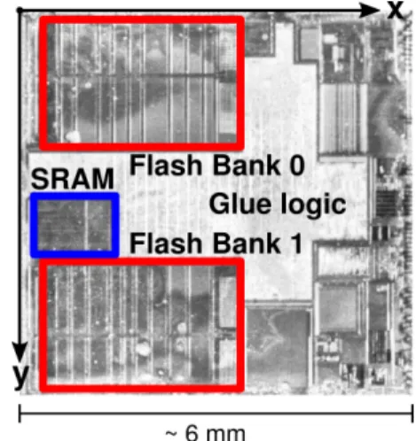
The experiments were conducted on the 32-bit micro-controller SAM3X8E. It features a cortex-M3 core with the thumb2 instruction which consists of 16-bit and 32-bit instructions. It embeds two banks of 256 kB NOR Flash memory and a 96 kB SRAM. The physical placement of the memories is highlighted on Figure 1. The core and the peripherals are clocked at 84 MHz.
B. Setup
Our EM pulse injection setup is depicted in Figure 2. The voltage pulse generator delivers a square voltage pulse with a transition time of 2 ns, a maximum amplitude of 200 V in absolute value, and a minimum width of 6 ns. The voltage pulse is converted into a current variation in the coil at the tip of the handcrafted injection probe shown in Figure 3. The probe is made of three turns of copper wire around a ferrite core about 500 µm in diameter. It is attached to a micrometer positioning table, which coordinates in the target referential are denoted by x and y over the the surface of the device, and z in the orthogonal direction. The z-coordinate is fixed, so that the distance between the die and the probe tip is about the thickness of the LQFP package. A trigger signal generated by the device under test synchronizes the voltage pulse with the operation of the microcontroller. A constant delay can be set between the rising edge of the trigger and the generation of an electromagnetic pulse. A personal computer sets the injection parameters and orchestrates the operation of the positioning table, the pulse generator, and the device under test.
Figure 2: Schematic of the EM pulse injection setup
C. Methodology
A detailed black-box analysis of the physical effects of faults on a microarchitecture is often unpractical, as the lowest abstraction made available to an attacker is the instruction set architecture. Moreover, injected faults are captured as a corrupted state of memory cells, regardless if the physical effect of the fault corrupts the memory cell itself or the signal and its propagation before a sampling operation. While these considerations restrict one’s ambitions, the analysis of memory corruption provide a valuable insight into the parts of the microarchitecture that are sensitive to electromagnetic injection.
Previous work on electromagnetic injection highlighted that faults could be induced with a high probability during the sampling operation of D flip-flop memory cells [4]. Moreover, we did not observe any static corruption of data at restin the Flash memory and the SRAM. Therefore, we investigated the effects of electromagnetic injection on data in transitduring a transfer between the Flash memory and the register file. Based on these considerations, we highlight in Figure 4 four microarchitectural features in the datapath of the microcontroller which are potentially sensitive to electromagnetic injection: the Flash memory (1), the 128-bit prefetch buffer (2), the bus interfaces (3), and the register file (4).
To distinguish between these scenarios, we characterized the effects of fault injection during the execution of the test routine given in Listing 1. First, registers r1 to r12
Figure 3: Handmade flat tip injection probe
Figure 4: Potential fault scenarios: on the Flash memory operation (1), on the prefetch buffer (2), on the bus interfaces (3), on the register file (4)
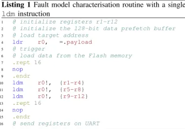
Listing 1 Fault model characterisation routine with a single ldminstruction
1 @ initialize registers r1-r12
2 @ initialize the 128-bit data prefetch buffer
3 @ load target address 4 ldr r0, =.payload
5 @ trigger
6 @ load data from the Flash memory
7 .rept 16 8 nop 9 .endr 10 ldm r0!, {r1-r4} 11 ldm r0!, {r5-r8} 12 ldm r0!, {r9-r12} 13 .rept 16 14 nop 15 .endr
16 @ send registers on UART
are initialized, along with the 128-bit data buffer. Then, the address of four 32-bit consecutive words is loaded in register r0. These four words consist in 128 bits in Flash memory bank 0 aligned on the prefetch buffer. The transfer of data between the Flash memory and the register file can be achieved by mean of the Load Multiple (ldm) instruction on cortex-M microcontroller. Note that various load instruction can be used for this purpose, we observed the same fault model using consecutive ldr instructions. The ldm r0!, {rX-rY}instruction loads consecutive words in registers rX
to rY from the address stored in r0 and increments register r0. The instructions under test are separated from the rest of the code with several nop instructions. Finally, the value of the registers are sent back to the personal computer to be analyzed with respect to the initialization state and the injection parameters.
As we did not observe any corruption of instructions fetched from the SRAM, we relocated the test routine in SRAM as proposed in [14] to specifically target the data prefetch buffer. This strategy allowed us to overcome the difficulty in distinguishing between instruction and data corruption.
In the next section, we investigate four different fault models and demonstrate that the data prefetch buffer can be precisely targeted.
IV. FAULT MODEL CHARACTERIZATION
An extensive vocabulary is used to describe the versatile nature of a fault model from the perspective of an attacker. In
Figure 5: Sensitive area to EM fault injection
this article, we adopt the following definition to characterize the nature of a fault: A fault is called transient if its effect on the circuit operation is limited in time. On the contrary, a fault is called permanent or destructive if it has a definitive effect on the circuit. Furthermore, we adopt the following designations to describe the effects of a fault:
• bitset: the value of a bit is set to one
• bitreset: the value of a bit is set to zero
• bitflip: the value of a bit is complemented
• update fault: a bit is stuck to its previous value A. A first set of injection parameters
We move the probe over the entire die area and try several delays to find a suitable injection spot, where a corruption of a memory transfer could be observed. The width of the pulse is fixed to 6 ns, which is the lowest possible value with our setup. The spot area sensitive to EM injection is 3 mm in diameter, as shown in Figure 5. It is approximately located around the upper Flash memory bank in Figure 1. Note that the origin of the referential is located outside of the chip area, at a corner of the chip package. We fix the probe location at coordinates (8 mm, 8.5 mm), highlighted in red on Figure 5, where a repeatable corruption of four registers had been observed. We characterize the influence of the injection timing on observed fault models in the next paragraph.
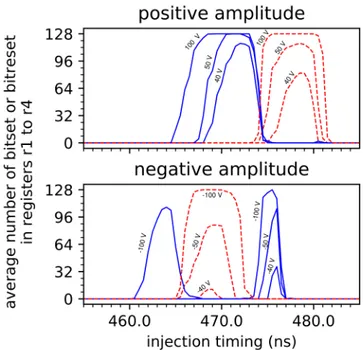
B. A temporal characterization of observed fault models The average number of corrupted bit in 128 consecutive bits loaded from the Flash memory as a function of the injection delay and the pulse polarity for different values of the pulse amplitude is given in Figure 6.
Zeroes fetched from the Flash memory could be set to one (blue curve) and ones fetched from the Flash memory could be reset to zero (red curve) for different values of the
Figure 6: Average number of corrupted bit as a function of the injection delay, loading four all-zero words (blue) and four all-one words (red) in registers r1 to r4 for positive (top) and negative (bottom) pulse amplitude
delay. Different initialization values of the registers and the buffer, all ones, all zeroes, mixing ones and zeros, lead to the same characterization results. Thus, we conclude that both bitset and bitreset faults can be induced on the target microarchitecture for different settings of injection delay and pulse polarity. Note that 128 bits aligned with the prefetch buffer can be simultaneously set with a pulse amplitude of 100 V and reset with a pulse amplitude of -100 V with a
repeatability of 100% for 20 repetitions at 471 ns.
We observed that more bits could be corrupted simultane-ously with a positive polarity than with a negative polarity for the same pulse amplitude. Moreover, the highest temporal resolution while still being able to corrupt 128 bits was achieved for a pulse amplitude of 70 V. Therefore a positive pulse amplitude of 70 V is preferred in the remaining of this paper. In the next paragraph, we characterize the effect of the injection timing on sequential ldm instructions. C. Evidence of faults on the data prefetch buffer
The 128-bit data prefetch buffer improves the execution time of sequential access to consecutive words in Flash memory by preloading four 128-bit aligned words with a single access to the Flash memory. This mechanism is critical for system performance, as a reading operation in the Flash memory is several time slower than the maximum operating frequency of the system. Additional Flash Wait State (FWS) can be set in the memory controller, so that the core stalls several cycles to wait for a memory access to complete.
Figure 7: Index of corrupted bits as function of the EM injection delay
The position of corrupted bit in the 128-bit data buffer as a function of the injection delay for three consecutive ldm instructions and a constant pulse amplitude of 70 V is given in Figure 7. Bitset fault are colored in blue, bitreset fault are colored in red. We observe that the transfer of consecutive words can be corrupted by group of four words for registers r1to r4, r5 to r8 and r9 to r12, every 9 clock cycles at 84 MHz.
This phenomenon can be explained by the execution of two consecutive ldm instructions in the 3-stage pipeline (Fetch, Decode, Execute) of the cortex-M3 core as shown in Figure 8. The execution stage of a load instruction is divided into the address calculation (Ea) and the transfer of a word into a given register rX (ErX). Note that the first data request to 128 bits in the Flash memory is performed during the address phase, while the four words are loaded sequentially on the bus during the loading phase. Related address and data transactions in the 2-stage pipeline of the AHB bus is not represented to improve the clarity of the diagram. Taking into account the four cycles of stall (FWS) requested by the Flash controller, consecutive ldm instructions trigger a reading operation and a subsequent update of the data buffer of the Flash memory every 9 clock cycles.
These considerations highlight that the sampling operation of 128 bits in the data prefetch buffer is sensitive to electromagnetic injection. We fix the injection delay at 471 ns, where all the bits in the data prefetch buffer could be set
Figure 8: Timing diagram of sequential ldm instructions in a 3-stage pipeline
with a high repeatability, to characterize the influence of the probe location on the position of corrupted bits in the buffer. D. A spatial characterization of observed fault models
As we do not observe any exploitable effect of the x-coordinate on the fault model, it is fixed to 8 mm.
The index of corrupted bits as a function of the probe y-coordinate by step of 50 µm is shown in Figure 9. The correlation between the probe y-coordinate and corrupted bits can be leveraged by an attacker to fault either the least significant bits of a 32-bit word for values of y lower than 8.6 mm, or the most significant bits of 32-bit words for values of y greater than 8.6 mm. The same result have been observed for bitreset fault with a different injection delay.
The similar fault pattern modulo 32 bits in Figure 9
Figure 9: Position of bitset as a function of the y-coordinate of the injection probe for a pulse amplitude of 70 V
Figure 10: Hypothesis on the architecture of the interface between the bus and the 128-bit data buffer
suggests that the physical placement of the 128 bits stored in the data buffer differ from the logical numbering from 0 to 127. An illustative example, where latches are organized by group of four on several multiplexer, is depicted on Figure 10. The spatial accuracy of electromagnetic injection allows an attacker to target whole or a selected part of the data prefetch buffer with a high repeatability. This aspect is exploited in the practical case studies.
V. PRACTICALCASESTUDIES
To validate the applicability of the discovered fault model for practical attack, we target a public implementation of AES [7]. Our threat model assumes that the attacker has access to a physical instance of the target device. Full control over another instance of the same device is required to adjust the injection parameters, based on the methodology and the results of Section IV. A 128-bit secret key is originally stored in a readout protected Flash memory of the target device. Target implementation code is located in the Flash memory as part of the device microcode to secure the device communication. The key is kept in the Flash memory and loaded in registers only when an encryption or a decryption is performed to deter snapshot attacks on non-protected SRAM [15]. In the persistent fault attack scenario, the S-box is copied in SRAM before several block cipher encryptions to reduce the execution time of an encryption. Moreover, we assume that the attacker is able to synchronize an EM pulse on the device operation.
A. Case Study 1: Key zeroing/setting attack
A straightforward implementation of our fault model is to set or reset a 128-bit key as it is fetched from the Flash memory. In this scenario, an attacker with a physical access to the device does not need to know the secret key to decrypt the content of collected ciphertext. However, an attacker should be able to specifically target the data path. In the previous section we demonstrate that it can be easily achieved on the target architecture when the code is located in SRAM. In this section, we report that it is still the case when the code is fetched from the Flash memory on the optimized
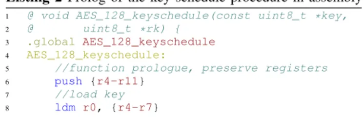
Listing 2 Prolog of the key schedule procedure in assembly
1 @ void AES_128_keyschedule(const uint8_t *key, 2 @ uint8_t *rk) {
3 .global AES_128_keyschedule 4 AES_128_keyschedule:
5 //function prologue, preserve registers 6 push {r4-r11}
7 //load key 8 ldm r0, {r4-r7}
implementation of AES-128 for cortex-M microcontroller provided in [7].
The assembly code used to transfer the 128-bit key in the register file at the beginning of the key scheduling procedure is shown in Listing 2. The address of the secret key is a constant pointer given as the first argument of the key scheduling procedure const uint8_t *key. According to the ARM calling convention, this address is stored in register r0. The second argument of the procedure uint8_t *rk is a pointer on the round keys located in SRAM. The instruction ldm r0, {r4-r7} transfers the 128-bit secret key from the Flash memory to the registers r4, r5, r6, r7. We successfully set the whole key and reset the whole key for two different injection delays with 100% repeatability for 100 repetitions while both instruction and data were fetched
from the Flash memory.
The key could be set during a sensitive window of 2 ns, between 635 ns and 636 ns. The key could be reset during a sensitive window of 2 ns, between 639 ns and 640 ns. B. Case Study 2: Baseline DFA from Biham and Shamir
In 1997, Biham and Shamir published a cryptanalytic attack on the key of a unknown cryptosystem [13]. While the pedagogical interest of this attack has been previously highlighted, its practical implementation was commonly thought to be far from trivial. The attack assumes that one has the capability to collect the encryption results of a known plaintext while resetting one bit of the secret key at a time until the all-zero key is reached. Going backward, the secret key can be recovered bit per bit from the all-zero key with at most n(n−1)2 hypothesis on the position of the ones.
In Section IV, we highlighted the dependency between the position of the injection probe and the position of corrupted bits. More specifically, starting with the y-coordinate set to 8.5 mm, all the bits of the key can be set to one as shown in Figure 9. As the probe move along the y-coordinate toward 7 mm, the probability to fault any of the most significant bits decreases to zero. Thus, the most significant bit can be easily recovered. On the other hand, as the probe move along the y-axis toward 10 mm, the probability to fault the less significant bits decreases to zero, and the same procedure can be applied. The exploitation of bitreset faults further accelerates the convergence of this attack.
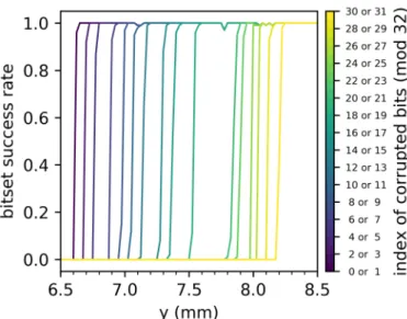
The probability that at least one bit among eight is set by an electromagnetic injection as a function of the
Figure 11: Bitset success rate as a function of the probe y-coordinate, with a pulse amplitude of 70 V and a constant injection delay
probe y-coordinate is given in Figure 11. The notation 30 or 31 denotes that at least one bit among the eight bits 30, 31, 62, 63, 94, 95, 126, 127 is corrupted. The probability to corrupt at least one bit among these bits drop to zero if the probe y-coordinate is below 8.2 mm on as shown in Figure 11.
In this experiment, the precision of the positioning table should be about 25 µm to set (or reset) all but 8 specific unknown bits, thus reducing the key space to 16 × 28 possibilities.
C. Case Study 3: Persistent fault analysis
In [16], F. Zhang et al. proposed a novel fault analysis technique against block ciphers called persistent fault analysis (PFA). PFA is based on persistent faults that persists over several encryptions and disappear on reboot. The attack needs a persistent fault in one (or few) elements of the Sbox look-up table. Any encryption with this corrlook-upted Sbox results in faulty ciphertext if the corrupted entry is accessed during the encryption Some encryption never access the corrupted entry resulting in correct ciphertext. Key recovery is done through statistical analysis on a pool of output ciphertext. Attack is still possible if multiple persistent faults are injected in the Sbox table, at the cost of increased brute force. More details on the attack can be found in [16].
In the following, we validate the potential of injecting a persistent fault in the target public code of [7]. The table lookup is implemented with a single T-table of 1 kB and three rotations per round for each column. As a result, all the 16 bytes of the key can be potentially recovered if a corruption of the substitution layer is possible. Let T [v] be a 4-byte column of the T-table, and• be the multiplication modulo
Listing 3 C memcpy procedure used to relocate the T-table in SRAM
1 /* relocate */ 2 pSrc = &_etext;
3 pDest = &_srelocate;
4 for(; pDest < &_erelocate ;){
5 *pDest++ = *pSrc++;
6 }
0x11Bin the finite field GF (28). Then the column T [v] of the T-table is given as a function of the S-box coefficient S[v]:
T [v] = [S[v]•01; S[v]•02; S[v]•03; S[v]•01] (1)
Note that the T-table representation embeds a form of data duplication. We confirmed with an exhaustive simulation based on the characterization of our fault model that setting or resetting only part of a 32-bit register could not emulate the corruption of a single element in the S-box. However, the null element of the S-box corresponds to the null word in the T-table. Thus, resetting 32 bits of a register successfully emulates a single S-box corruption, and resetting the data prefetch buffer emulates between three and four S-box corruptions. We practically verified that 100% repeatability could be achieved for a constant injection delay during a call to the relocation function presented in Listing 3. This attack theoretically reduces the key entropy to 32 bits, considering that four elements of the S-box are corrupted [16], which is practical to brute force (232).
VI. CONCLUSION
In this paper, we demonstrate on experimental basis that EMFI makes it possible to corrupt data fetched from the embedded Flash memory of a microcontroller with no observable effect on the code execution. We studied the influence of the probe location and the temporal parameters of the electromagnetic pulse on the observed fault model. A bit level accuracy in the fault injection process was achieved through a careful tuning of the EM injection parameters. We investigated three case studies on a public AES implementation and demonstrated that practical attack on cryptographic ciphers do not require the corruption of instructions. These case studies highlight the vulnerability of unencrypted memories to targeted data corruption.
REFERENCES
[1] Dan Boneh, Richard A. DeMillo, and Richard J. Lipton. On the importance of eliminating errors in cryptographic computations. 14(2):101–119.
[2] Jörn-Marc Schmidt and Michael Hutter. Optical and em fault-attacks on crt-based rsa: Concrete results. In Austrian Workhop on Microelectronics, pages 61–67.
[3] Marjan Ghodrati, Bilgiday Yuce, Surabhi Gujar, Chinmay Deshpande, Leyla Nazhandali, and Patrick Schaumont. Induc-ing local timInduc-ing fault through EM injection. In ProceedInduc-ings of the Design Automation Conference, pages 1–6.
[4] Sébastien Ordas, Ludovic Guillaume-Sage, and Philippe Maurine. EM injection: Fault model and locality. In Workshop on Fault Diagnosis and Tolerance in Cryptography, pages 3–13.
[5] Amine Dehbaoui, Jean-Max Dutertre, Bruno Robisson, and Assia Tria. Electromagnetic transient faults injection on a hardware and a software implementations of AES. In Workshop on Fault Diagnosis and Tolerance in Cryptography, pages 7–15.
[6] Nicolas Moro, Amine Dehbaoui, Karine Heydemann, Bruno Robisson, and Emmanuelle Encrenaz. Electromagnetic fault injection: Towards a fault model on a 32-bit microcontroller. In Workshop on Fault Diagnosis and Tolerance in Cryptography, pages 77–88.
[7] Peter Schwabe and Ko Stoffelen. All the AES you need on cortex-m3 and M4. In Selected Areas in Cryptography, volume 10532, pages 180–194.
[8] Lionel Rivière, Zakaria Najm, Pablo Rauzy, Jean-Luc Danger, Julien Bringer, and Laurent Sauvage. High precision fault injections on the instruction cache of armv7-m architectures. In International Symposium on Hardware Oriented Security and Trust, pages 62–67.
[9] H. Liao and C. Gebotys. Methodology for em fault injection: Charge-based fault model. In Design, Automation Test in Europe Conference Exhibition, pages 256–259.
[10] Julien Proy, Karine Heydemann, Fabien Majéric, Albert Cohen, and Alexandre Berzati. Studying EM pulse effects on superscalar microarchitectures at ISA level. abs/1903.02623.
[11] Yuan Yao, Mo Yang, Conor Patrick, Bilgiday Yuce, and Patrick Schaumont. Fault-assisted side-channel analysis of masked implementations. In International Symposium on Hardware Oriented Security and Trust, pages 57–64.
[12] Ang Cui and Rick Housley. BADFET: defeating modern secure boot using second-order pulsed electromagnetic fault injection. In USENIX Workshop on Offensive Technologies.
[13] Eli Biham and Adi Shamir. Differential fault analysis of secret key cryptosystems. In Advances in Cryptology - CRYPTO ’97, volume 1294, pages 513–525.
[14] Louis Dureuil, Marie-Laure Potet, Philippe de Choudens, Cécile Dumas, and Jessy Clédière. From code review to fault injection attacks: Filling the gap using fault model inference. In International Conference on Smart Card Research and Advanced Applications, volume 9514, pages 107–124.
[15] Johannes Obermaier and Stefan Tatschner. Shedding too much light on a microcontroller’s firmware protection. In USENIX Workshop on Offensive Technologies.
[16] Fan Zhang, Xiaoxuan Lou, Xinjie Zhao, Shivam Bhasin, Wei He, Ruyi Ding, Samiya Qureshi, and Kui Ren. Persistent fault analysis on block ciphers. 2018(3):150–172.