HAL Id: hal-01432155
https://hal.archives-ouvertes.fr/hal-01432155
Submitted on 11 Jan 2017
HAL is a multi-disciplinary open access
archive for the deposit and dissemination of
sci-entific research documents, whether they are
pub-lished or not. The documents may come from
teaching and research institutions in France or
abroad, or from public or private research centers.
L’archive ouverte pluridisciplinaire HAL, est
destinée au dépôt et à la diffusion de documents
scientifiques de niveau recherche, publiés ou non,
émanant des établissements d’enseignement et de
recherche français ou étrangers, des laboratoires
publics ou privés.
Solvent-Free Electrolytes for Electrical Double Layer
Capacitors
Léo Nègre, Barbara Daffos, Pierre-Louis Taberna, Patrice Simon
To cite this version:
Léo Nègre, Barbara Daffos, Pierre-Louis Taberna, Patrice Simon. Solvent-Free Electrolytes for
Elec-trical Double Layer Capacitors. Journal of The Electrochemical Society, Electrochemical Society,
2015, 162 (5), pp.A5037-A5040. �10.1149/2.0061505jes�. �hal-01432155�
To link to this article : DOI : 10.1149/2.0061505jes
URL : http://dx.doi.org/10.1149/2.0061505jes
O
pen
A
rchive
T
OULOUSE
A
rchive
O
uverte (
OATAO
)
OATAO is an open access repository that collects the work of Toulouse researchers and
makes it freely available over the web where possible.
This is an author-deposited version published in :
http://oatao.univ-toulouse.fr/
Eprints ID : 16800
To cite this version :
Negre, Léo and Daffos, Barbara and Taberna,
Pierre-Louis and Simon, Patrice Solvent-Free Electrolytes for
Electrical Double Layer Capacitors. (2015) Journal of The
Electrochemical Society (JES), vol. 162 (n° 5). pp. A5037-A5040.
ISSN 0013-4651
Any correspondence concerning this service should be sent to the repository
administrator: [email protected]
Solvent-Free Electrolytes for Electrical Double Layer Capacitors
L. N`egre,a,bB. Daffos,a,bP. L. Taberna,a,band P. Simona,b,∗,z
aLaboratoire CIRIMAT, UMC CNRS 5085, Universit´e Paul Sabatier Toulouse III, 31062 Toulouse Cedex, France bR´eseau sur le Stockage Electrochimique de l’Energie (RS2E), FR CNRS 3459, France
A mechanically-stable non-aqueous inorganic gel polymer electrolyte that is based on association of sol-gel agents and Ionic Liquid is considered here for application in solid-state solvent free supercapacitors. The first part is devoted to the electrochemical characterization of the ionogel bulk properties. In the second part, an electrochemical cell using activated carbon as active materials and the new ionogel electrolyte has been characterized over a wide temperature range using cyclic voltammetry and electrochemical impedance spectroscopy. The use of high IL content (70%) has led to an increase of both the operating voltage window (up to 3 V) and the electrolyte ionic conductivity (around 4.7 mS/cm). The resulting double layer capacitance of the microporous activated carbon device was found to be as high as 80 F/g; even more important, this quasi solid electrolyte works well over a wide temperature range (namely, from −30 to more than 80◦C).
DOI:10.1149/2.0061505jes
Electrochemical Capacitors (ECs), also known as supercapacitors, have now reached the technical maturity for complementing– and sometimes replacing– batteries in a large range of applications from power electronics to transportation such like in hybrid electric ve-hicles or trams.1 They are currently used for high power delivery for few seconds or tens of seconds as well as for energy recovery (braking energy in cars, kinetic energy in cranes or elevators. . . ). Despite the abounding research on pseudocapacitive materials with promising performance2–6Electrochemical Double Layer Capacitors (EDLCs) using porous carbons as active material are still by far the most commercialized devices.7One of the most important challenge the technology is currently facing is the improvement of the maxi-mum energy density, which depends from the capacitance and the cell voltage through the equation1
E =1 2C · V
2 [1]
Where C stands for the capacitance (F), V the cell voltage (V) and E the energy (J).
While the improvement of the capacitance has led to important discoveries in the ion transport and adsorption in confined pores of nanoporous carbons,8,9 the increase of the cell voltage is still today limited by the electrolyte stability windows. During long time, con-ventional electrolytes based on acetonitrile or propylene carbonate solvents have been used in combination with ammonium cations and fluoride anions.4More recently, mixtures of various carbonate-based solvents used in Li-ion batteries have been proposed by Lust’s group, with an increase of the supercapacitor cell voltage up to 3 V.10 How-ever, such electrolytes are known to be highly sensitive to moisture and the formation of a Solid Electrolyte Interphase (SEI) in carbon micropores, blocking further ion accessibility these pores.11
Another strategy is to design new electrolytes or solvents.12Such an approach is certainly one of the most promising in terms of per-formance improvement but, at the same time, the most complex since new solvents or electrolytes must match multiple criteria (conduc-tivity, viscosity, electrochemical stability. . . ). Interesting work was recently done by A. Balducci et al. has recently proposed the use of adiponitrile for replacing acetonitrile.13,14Although cell voltage up to 3.5 V were demonstrated with a decent stability during cycling, adiponitrile-based electrolytes suffer from a limited conductivity (4 mS/cm) and a high viscosity (6 mPa.s) at room temperature restricting their use to temperature higher than 0◦C.13
The same restriction applies to Ionic Liquids (ILs) that are solvent-free electrolytes, liquid at room temperature. The large
electrochem-∗
Electrochemical Society Active Member.
zE-mail:[email protected]
ical voltage window (up to 4 V)10they can offer is balanced by their limited ionic conductivity and high viscosity at room temperature.4 As a result, porous carbon-based supercapacitors using neat ILs as electrolytes show very good electrochemical performances at temper-atures higher than Room Temperature (RT),15,16 but fail in a large extent to maintain such performance below RT.
Protic Ionic Liquids (PILs) are ILs where a proton can be trans-ferred from a Br¨onsted acid to a Br¨onsted base.17PILs are easier to synthesize, less viscous and show higher conductivities than aprotic ionic liquids.18As a result, capacitance beyond 100 F/g were reported for porous carbons at room temperature, with decent low temperature behavior with about 40% loss at −10◦C.19However, the easy pro-ton transfer narrows the electrochemical voltage windows because of redox reactions, resulting in maximum voltage of about 2 V.20
In summary, none of the approaches described above has been successful for designing electrolytes that fully match all the criteria of the ideal – high conductivity, low viscosity, large voltage window and operation temperature range – and it is a safe bet that we are not that close to reach the goal.
However, ILs being solvent-free, nonvolatile and nonflammable electrolytes, they are very appealing candidates for replacing the con-ventional solvent-based liquid electrolytes, including the one contain-ing acetonitrile. Indeed, the low boilcontain-ing point (81.6◦
C), high vapor pressure (9.7 kPa at 20◦C) and high flammability (flash point = 2◦C)
of acetonitrile is a source of concern in some applications, from the safety point of view; replacing the acetonitrile with a solvent-free electrolyte would thus first alleviate such safety issues. Going fur-ther, moving from liquid to solid electrolytes is also of great interest in the aim of solving packaging issues, corrosion, self-discharge or leaks.18,21The key issue to tackle in this aim is to achieve high me-chanical stability while retaining high ionic conductivity. Last but not least a good contact at electrolyte-electrode interphase is required, in order to preserve decent gravimetric capacitance temperature behav-ior below RT. This is particularly true for EDLCs where high surface area carbons are used as active materials.
In this paper, we will present results about the synthesis and char-acterization of a quasi-solid-state supercapacitor using ionogel solvent free electrolytes, whose concept was recently pioneered by Brousse’s group.22Such devices could efficiently replace liquid-based systems for improving the safety, corrosion and the packaging of supercapac-itors, thus extending the range of applications of these systems.
Experimental
Ionogel synthesis.—Ionogels were achieved by trapping into a functionalized silica an ionic liquid (1-ethyl-3-methyl imidazolium bis(trifluoromethanesulfonylimide), EMITFSI 99.9% (purchased
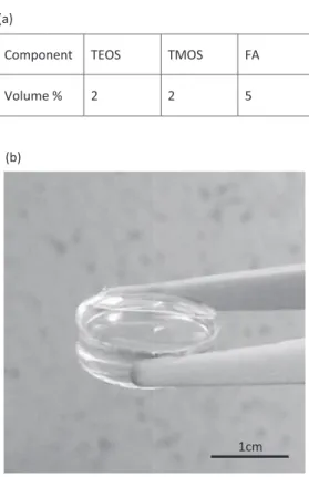
Figure 1. Volume ratio for ionogel sol synthesis (a) and ionogel lingot picture (b).
from Sovlionic, France) through a sol-gel process. An organic based sol-gel route was preferred in this work to create a very fine poros-ity (G.Sharp et al)23consisting in a mixture of two silica precursors (TetraEthyl OrthoSilicate and TetraMethyl Ortho Silicate, from Sigma Aldrich) with Formic Acid (FA, 98% purchased from Arcos Organ-ics) as a catalyst agent. FA was mixed to the silica precursors under moderate stirring (200 rpm) at 40◦
C during 20 minutes to initiate
sol-gel hydrolysis reactions. Then 70%vol. of EMITFSI was added and stirring was achieved 2 more minutes. The amount of ionic liquid also was found out elsewhere to be an optimum in term of mechani-cal behavior and ionic conductivity.24Sol+IL mixture was casted in sealed containers and kept for 1 day at RT for gelation and was then aged in vacuum oven during 4 days at 120◦
C to remove sol-gel reac-tion byproducts (water, alcohol . . . ) and residual FA.23,24Monolithic pieces of wet gels were then obtained (see Figure1b). Such silica-based ionogels could be described as two interconnecting networks of silica and ionic liquid at nanometer scale. The trapped-IL experi-ences a large interface with pore walls which is expected to modify its microscopic structure and dynamics compare to the bulk phase.25,26 Clear and crack-free gels were obtained tuning silane to acid volume ratio to 4:5.27Volume ratios are reported in Figure1a.
Electrochemical tests were carried out using an Autolab PG-STAT128N (Metrohm, Switzerland). A RHD cell (RHD, Germany) was used for the tests which enable to finely control the cell tem-perature from −35 up to 80◦C. All the cells were assembled in a
MBra¨un glove box (O2and H2O contents lower than 0.1 ppm). Ionic
conductivity vs temperature of the synthesized gels was measured through Electrochemical Impedance Spectroscopy using two gold current collectors. Supercapacitor cells were assembled using gold platinum current collectors on which activated carbon based active material films were casted. Active material was made of 95 wt% of PICACTIF SC, which is a standard high specific surface area activated carbon (2300 m2/g),28and 5 wt% of PTFE (60 wt% PTFE in water DuPont Nemours, France).29Few droplets of Silane-IL mixture was deposited onto the electrodes and then sandwiched. The gel formation was obtained following procedure previously described. This tech-nique is really simple and offers a possible way to work with a large amount of active material (from few mg up to 15 mg/cm2).28After aging, the ionogel is placed in a RHD cell for further electrochemical tests.
Results and Discussion
Ionic conductivity.—Figure2shows the change of conductivity of the ionogel with temperature (Arrhenius plot) between −35◦
C and 80◦
C. First it should be noted that ionogel conductivity (4.7 mS/cm at 20◦
C) is close to that of neat IL (8 mS/cm at RT). Such conductivity
Figure 2. (a) Arhenius plot of ionogel between −35◦C and 80◦C. Conductivities were calculated from high frequency intercept with real axis of the Nyquist Plots; exemple are given in 2(b).
Figure 3. (a) 3 V operating voltage Cyclic Voltammetry of ionogel sample at 5, 10 and 20 mV/s scan rate. (b) CV at different temperature (from −20 to +80◦C). (c) Optical microscopy picture of an ionogel based activated carbon sandwich. (d) Picture of a gelled activated carbon electrode.
values match with the requirement needed for use as electrolyte free solvent.30
Actually, from −30 to 80◦
C the conductivity follows an Arrhenius plot with an activation energy of 2.6 kJ/mole. Such low activation energy confirms an appreciate ion mobility. Moreover, these results show that even below the ionic liquid freezing point (−16.1◦C), the
ionogel solvent free is still conductive at −30◦C; this is assumed to be
linked with the confinement of EMITFSI. The crystallization temper-ature shifts from −16◦C down to –30◦C; at −35◦C the crystallization
process starts. Such a behavior has been reported elsewhere by Le Bideau et al.31,25
Ionogel-based supercapcitor: design and efficiency:.—An all solid supercapacitor was tested by Cyclic Voltammetry (CV) at 5 mV/s between 0 and 3 V at RT. The rectangular shaped cyclic volatammetry induces capacitive storage with the porous carbon. A gravimetric ca-pacitance close to 80 F/g was calculated from the CV, which is close to the one obtained in liquid electrolyte.29Although the increase of the sweep rate, up to 20 mV/s, led to a distortion of the CV because of the ohmic drop, the capacitive signature is still preserved, associated with a limited loss (∼20%), evidencing decent power capability.
Figure3ashows the CVs recorded at 5 mVs between −20◦C and
80◦C, after one hour stabilization at set temperature. The capacitive
behavior is kept down to temperature as low as −10◦
C, while keeping
a constant capacitance in this temperature range. These results are consistent with Figure2bthat showed that ionic mobility was still high at such low temperature. The low capacitance at −20◦
C is assumed to come from the crystallization of the IL in the confined pores of the carbon structure.31Nevertheless, lower working temperature (at least down to −30◦C) could be reached using more open carbon
structures, like it has been already shown.30 Figure3cshowing an optical cross section microscopy picture using an optical Keyence VHX1000 digital microscopy. The cracks came from the cut. The specific capacitance of the PICACTIF SC activated carbon is around 95 F/g in neat EMITFSI.28,32Our device shows for a 3 V operating cell voltage a 80 F/g gravimetric capacitance at RT which is not so far from the value obtain in liquid state.
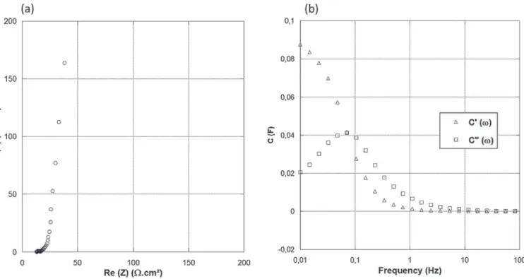
Figure4ashows the Nyquist plots at a bias cell voltage of 0 V with a signal amplitude of 5 mV RMS, from 1 MHz down to 0.01 Hz. At very low frequency, the quasi-vertical line observed shows the capacitive behavior of the system. The transition between these two regimes, indicated by a linear Warburg-like behavior, originates from the porous network of the activated carbon. This region corresponds to the “penetration” of the electrolyte into the porous structure of the elec-trode. Once the total capacity of electrode is reached, the imaginary part sharply increases. The difference between the high-frequency resistance and the extrapolation of the low frequency linear capaci-tive behavior on the real part axis defines the electrolyte resistance
Figure 4. (a) EIS Plot of ionogel-based activated carbon supercapacitor. (b) Impedance plot using complex capacitance model.
inside the carbon porous network. The frequency behavior of the cell was analyzed using a complex capacitance model, based on the mod-eling of the capacitance in real part C′(ω) and imaginary part C′′(ω),
both functions of the frequency: C′ = −Z′′ /ωZ2 [2] C′′ = −Z′ /ωZ2 [3]
Where C′is the real part and C′′is the imaginary part of the capacitance
C. ω is the angular frequency and Z stands for the impedance modulus. Figure4b shows the change of the real part of the capacitance C′
with frequency. The graph shows a transition from purely resistive behavior at high frequency (phase angle close to 0) to purely capacitive behavior at low frequency (around 0.1 Hz).The whole capacitance of the electrode is not reached even at around 0.01 Hz. The relaxation time τ0in this system is 10 s, which can be calculated from τ0=1/f0,
where f0is the frequency corresponding to the maximum of the curve
of C′′vs. f, in our case f
0=0.1 Hz.28Despite the use of a solid state
electrolyte, this value is in the same range as the one reported for liquid electrolytes, thus demonstrating the interest of ionogel electrolytes for supercapacitors.28
Conclusions
In this paper were presented the results obtained with carbon-carbon ionogel-based supercapacitor exhibiting decent capacitive be-havior over a wide temperature range (−30◦C +80◦C), thanks to
conductivity of synthetized ionogel (4.7 ms/cm at 20◦C). Such
tem-perature stability was ascribed to ionic liquid confinement. Assembled devices with such ionogel led to achieve all solid supercapacitor with attractive real capacitance higher than 150 mF/cm2per electrode at 1
mV/s and stable up to 3 V cell voltage. Such devices could efficiently replace liquid-based systems for improving the safety, corrosion and packaging issues of supercapacitors.
References
1. P. Simon and Y. Gogotsi,Nature Materials, 7, 845 (2008). 2. P. Simon, Y. Gogotsi, and B. Dunn,Science, 343, 1210 (2014).
3. W. Sugimoto, K. Yokoshima, Y. Murakami, and Y. Takasu,Electrochimica Acta, 52, 1742 (2006).
4. F. B´eguin, V. Presser, A. Balducci, and E. Frackowiak,Advanced Materials, 26, 2219 (2014).
5. V. Augustyn, P. Simon, and B. Dunn,Energy & Environmental Science, 7, 1597 (2014).
6. T. Brousse et al.,Journal of Power Sources, 173, 633 (2007). 7. J. R. Miller and P. Simon,Science, 321, 651 (2008). 8. J. Chmiola,Science, 313, 1760 (2006).
9. C. Largeot et al.,Journal of the American Chemical Society, 130, 2730 (2008). 10. M. Armand, F. Endres, D. R. MacFarlane, H. Ohno, and B. Scrosati,Nature Materials,
8, 621 (2009).
11. A. Lahe¨a¨ar, A. J¨anes, and E. Lust,Electrochimica Acta, 56, 9048 (2011). 12. E. Perricone et al.,Journal of Power Sources, 239, 217 (2013).
13. A. Brandt, P. Isken, A. Lex-Balducci, and A. Balducci,Journal of Power Sources,
204, 213 (2012).
14. A. Brandt and A. Balducci,Journal of the Electrochemical Society, 159, A2053 (2012).
15. C. Largeot, P. L. Taberna, Y. Gogotsi, and P. Simon,Electrochemical and Solid-State Letters, 14, A174 (2011).
16. M. Mastragostino et al.,ECS1, 55 (2006).
17. A. Fernicola, B. Scrosati, and H. Ohno,Ionics, 12, 95 (2006). 18. D. R. MacFarlane et al.,Energy & Environmental Science, 7, 232 (2014). 19. L. Timperman, H. Galiano, D. Lemordant, and M. Anouti,Electrochemistry
Com-munications, 13, 1112 (2011).
20. L. Timperman, F. Beguin, E. Frackowiak, and M. Anouti,Journal of the Electro-chemical Society, 161, A228 (2013).
21. M. Schroeder et al.,Journal of the Electrochemical Society, 160, A1753 (2013). 22. M. Brachet, T. Brousse, and J. Le Bideau,ECS Electrochemistry Letters, 3, A112
(2014).
23. K. G. Sharp,J Sol-Gel Sci Technol, 2, 35 (1994).
24. M.-A. N´eouze, J. L. Bideau, P. Gaveau, S. Bellayer, and A. Vioux,Chem. Mater., 18, 3931 (2006).
25. A. Vioux, L. Viau, S. Volland, and J. Le Bideau,Comptes Rendus Chimie, 13, 242 (2010).
26. A. K. Gupta, M. P. Singh, R. K. Singh, and S. Chandra,Dalton Transactions, 41, 6263 (2012).
27. B. S. Dunn, C. O. Chui, A. P. Jacob, D. Membreno, and L. Smith, (2014) Patent: US20140035098
28. P. L. Taberna, P. Simon, and J. F. Fauvarque,Journal of The Electrochemical Society,
150, A292 (2003).
29. J. Gamby, P. L. Taberna, P. Simon, J. F. Fauvarque, and M. Chesneau,Journal of Power Sources, 101, 109 (2001).
30. W.-Y. Tsai et al.,Nano Energy, 2, 403 (2013).
31. J. L. Bideau, P. Gaveau, S. Bellayer, M.-A. N´eouze, and A. Vioux,Phys. Chem. Chem. Phys., 9, 5419 (2007).
32. M. Lazzari, M. Mastragostino, and F. Soavi,Electrochemistry Communications, 9, 1567 (2007).