PIEZOELECTRIC FIBERS FOR SENSING AND ENERGY GENERATION
XIN LU
DÉPARTEMENT DE GÉNIE PHYSIQUE ÉCOLE POLYTECHNIQUE DE MONTRÉAL
THÈSE PRÉSENTÉE EN VUE DE L’OBTENTION DU DIPLÔME DE PHILOSOPHIAE DOCTOR
(GÉNIE MÉTALLURGIQUE) SEPTEMBRE 2018
ÉCOLE POLYTECHNIQUE DE MONTRÉAL
Cette thèse intitulée :
PIEZOELECTRIC FIBERS FOR SENSING AND ENERGY GENERATION
présentée par : LU Xin
en vue de l’obtention du diplôme de : Philosophiae Doctor a été dûment acceptée par le jury d’examen constitué de :
Mme SANTATO Clara, Doctorat, présidente
M. SKOROBOGATIY Maksim A., Ph. D., membre et directeur de recherche M. THERRIAULT Daniel, Ph. D., membre
ACKNOWLEDGEMENTS
I would like to express my deepest and heartfelt gratitude to my supervisor and research director, Prof. Maksim Skorobogatiy, for his guidance and support during my Ph.D. study, especially when I struggled in the predicaments. Prof. Skorobogatiy’s help allowed me to pursue successfully my scientific dream, become more mature, and enrich my curiosity.
I would like to thank all my friends and colleagues in Engineering Physics, Ecole Polytechnique de Montreal, Hang Qu, Tian Ma, Jingwen Li, Hichem Guerboukha, Katirvel Nallapan, Yang Cao and others. I would like to thank them for the helpful discussions, constructive interactions and mutual support in the past four years. I also would like to thank the technicians in our group, Francis Boutet and Yves Leblanc, for their plenty of technical assistance.
Finally, I wish to thank my parents for their unconditional support during my doctoral study. They have always been understanding and patient, and I could always address to them for the encouragement and support when I needed it.
Au cours de la dernière décennie, la recherche et le développement de générateurs fibrés a reçu une attention significative en raison de la popularité grandissante des appareils électroniques que l’on peut porter, tels que les écrans sur vêtements, les dispositifs de réalité virtuelle, les senseurs médicaux/cliniques portables et les montres intelligentes. Parmi les générateurs fibrés, les fibres piézoélectriques qui opèrent en se basant sur l’effet piézoélectrique sont spécialement attrayantes, parce qu’elles peuvent convertir les vibrations mécaniques de la vie quotidienne (causées par exemple par la marche, les courants d’air ou les battements cardiaques) en signaux électriques. Pour augmenter le potentiel des technologies portables, des textiles piézoélectriques pour alimenter les dispositifs électroniques ont été fabriqués en intégrant les fibres piézoélectriques dans des fibres commerciales utilisant les techniques de fabrication conventionnelles.
Les fibres piézoélectriques peuvent aussi avoir des applications techniques dans les domaines de l’information et des communications, dans l’automatisation industrielle, dans le diagnostic médical, dans le control du trafic et dans le secteur de la défense. Par exemple, ces fibres pourraient être implantées dans les avions et les véhicules pour surveiller l’intégrité de la structure mécanique, ainsi qu’alimenter les systèmes électroniques embarqués tels que les réseaux de senseurs sans-fil (WSN) à faible puissance. D’autres applications incluent les détecteurs acoustiques de haute-sensibilité pour la détection des ondes sonores, les actuateurs de micro-positionnement pour les microscopes à force atomique (AFM), les microscopes à effet tunnel (STM), les miroirs laser d’alignement et les dispositifs médicaux implantables (IMD).
Encouragés par le marché sans cesse grandissant des appareils électroniques portatifs, des efforts substantiels ont été investis dans la fabrication de fibres piézoélectriques. Aujourd’hui, la plupart des fibres piézoélectriques existantes sont fabriquées soit en faisant croître des nanostructures piézoélectriques dans un filament conducteur ou en extrudant des polymères piézoélectriques avec des polymères conducteurs par trempe sur roue (melt-spinning). La performance et les applications de ces fibres piézoélectriques sont limitées par leur géométries simpliste, leur grandes taille, leur faible fiabilité mécanique, leur coût élevé et leur faible réponse piézoélectrique.
Cette thèse a pour objectif de démontrer des fibres piézoélectriques micro et nanostructurées pouvant répondre à ces limitations. Dans notre approche, des fibres
piézoélectriques de plusieurs kilomètres de dimensions sous-millimétriques sont thermiquement étirées à partir de préformes macroscopiques. Les fibres piézoélectriques sont constituées d’un cœur creux mou de polycarbonate entouré d’une gaine de multicouches spiralées fait de couches alternatives de nanocomposites piézoélectriques (polyvinylidène augmenté avec BTO, PZT ou CNT) et de polymères conducteurs (polyéthylène rempli de carbone). Les deux couches de polymères conductrices jouent le rôle d’électrodes et forment des connecteurs électriques spatialement séparés pour faciliter la connexion. La structure multicouche de taille micro/nanométrique augmente l’efficacité de polarité grâce à la courte distance entre les électrodes conductrices entourant les couches piézoélectriques composites. Additionnellement, la structure en spirale augmente grandement la région active du composite piézoélectrique, en permettant la génération de voltage plus grande, résultant en des efficacités de génération de puissances de 10 à 100 fois plus importantes que les câbles piézoélectriques conventionnels.
Par la suite, nous avons réalisé une étude comparative des fibres piézoélectriques en utilisant trois combinaisons de matériaux (PVDF-BTO, PVDF-PZT et PVDF-CNT). La fibre microstructurée BTO/PVDF (longueur de 10 cm, concentration de BTO : 20 wt%) a pu générer un voltage en circuit-ouvert de 1.4 V et un courant de court-circuit de 0.8 nA, quand une des terminaisons de la fibre à été déplacée de 10 mm dans la direction transversale. Les voltages et courants correspondants étaient de ~6 V and ~4 nA pour la fibre de PZT-PVDF (20 wt% PZT) et de ~3V et ~1.2 nA pour la fibre de CNT-PVDF (0.4 wt%).
Comme exemples d’applications pratiques des fibres piézoélectriques proposées, nous présentons des textiles générateurs d’énergie utilisant des fibres BTO-PVDF, et nous caractérisons leurs performances dans le contexte de microgénérateurs que l’on peut porter. Nous présentons aussi la détection du son en utilisant des fibres CNT-PVDF avec des voltages piézoélectriques générés par des ondes sonores proportionnelles à la racine carrée de la puissance acoustique.
Additionnellement, nous avons assemblé des générateurs piézoélectriques planaires en sandwichant un nanocomposite piézoélectrique entre deux films de polymères conducteurs (C-LDPE). Les générateurs ainsi formés ont un voltage en circuit ouvert jusqu’à 8 V et un courant de court-circuit jusqu’à 40 nA avec une région active de plusieurs dizaines de cm2. La durabilité de ce générateur a été confirmée en répétant continuellement des mesures d’étirage pendant trois jours.
ABSTRACT
In the past decade, the R&D (research and development) of fiber generators has received significant attention due to the growing popularity of wearable mobile electronic systems such as on-garment displays, virtual-reality devices, wearable medical/clinic sensors and smart watches. Among all of these fiber generators, piezoelectric fibers that operate based on piezoelectric effect are especially attractive, because they could convert mechanical vibrations accessible in our daily life (i.e. walking, air flow and heart beating) into electrical signals. To make further improvements to the wearable applications, piezoelectric textiles that power on-body electronics have been fabricated by integrating piezoelectric fibers into commercial fabrics using traditional textile fabrication techniques.
Piezoelectric fibers can also find technical applications in the fields of information and communication, industrial automation, medical diagnostics, automation and traffic control, and in the defense industries. For instance, piezoelectric fibers could be implanted on the airplanes and vehicles, for the purpose of structural integrity monitoring, as well as powering the on-board electronic systems such as wireless sensor networks (WSNs) with low-power consumption. Other common examples include ultrasensitive sound detectors for stand-off sound detection, micro-positioning actuators for atomic force microscopes (AFM), scanning tunneling microscopes (STM), and laser mirror alignment; as well as power sources for implanted medical devices (IMDs).
Driven by the ever-growing market, extensive effort has been put into the fabrication of piezoelectric fibers. Currently, most of the existing piezoelectric fibers are fabricated either by growing piezoelectric nanostructures along a conductive filament or by extruding piezoelectric polymers together with a conductive polymer by melt-spinning. The performance and applications of these piezoelectric fibers are limited by their simple fiber geometries, large fiber size, poor mechanical reliability, high-cost, and low piezoelectric response.
This thesis aims to demonstrate micro- and nanostructured piezoelectric fibers that address these limitations. In our approach, kilometer-long piezoelectric fibers of sub-millimeter diameters are thermally drawn from a macroscopic preform. The piezoelectric fibers feature a soft hollow polycarbonate core surrounded with a spiral multilayer cladding consisting of alternating layers of piezoelectric electrospun nanocomposites (polyvinylidene enhanced with BTO, PZT or CNT) and
electrodes and form two spatially offset electric connectors on the fiber surface designed for the ease of connectorization. The micron/nano-size multilayer structure enhances in-fiber poling efficiency, thanks to the small distance between the conducting electrodes surrounding the piezoelectric composite layers. Additionally, the spiral structure greatly increases the active area of the piezoelectric composite, thus promoting higher voltage generation and resulting in 10-100 higher power generation efficiency over the existing piezoelectric cables.
Afterwards, we performed a comparative study of the piezoelectric fibers using three material combinations (PVDF-BTO, PVDF-PZT and PVDF-CNT). A BTO/PVDF microstructured fiber (10 cm long; BTO concentration: 20 wt%) could generate an open-circuit voltage of 1.4 V and a short-circuit current of 0.8 nA, when the moving end of the generator was displaced transversely by 10 mm. The corresponding voltage and current were ~6 V and ~4 nA for a PZT-PVDF (20 wt% PZT) fiber generator, and ~3 V and ~1.2 nA for a CNT-PZT-PVDF (0.4 wt% CNT) fiber generator.
As examples of practical applications of the proposed piezoelectric fibers, we present energy harvesting textiles using BTO-PVDF fibers, and characterized their performance in the context of wearable and automotive microgenerators. We also present detection of sound using CNT-PVDF fiber that feature piezoelectric voltage generated by sound wave to be proportional to the square root of the acoustic power.
Additionally, we have assembled piezoelectric planar generators by sandwiching a piezoelectric nanocomposite between two conductive polymer films (C-LDPE). Such planar generators can generate open-circuit voltages of up to 8 V and short-circuit voltage of up to 40 nA with an active area of several tens of cm2. The durability of this generator was confirmed by continuously repeating the bend-release measurements for 3 days. The generator retained well its piezoelectric voltage and current throughout the whole test that comprised ~26000 bend/release cycles.
TABLE OF CONTENTS
DEDICATION ... III ACKNOWLEDGEMENTS ... IV RÉSUMÉ ... V ABSTRACT ... VIII TABLE OF CONTENTS ... X LIST OF TABLES ... XIV LIST OF FIGURES ... XV LIST OF SYMBOLS AND ABBREVIATIONS ... XXIIICHAPTER 1 INTRODUCTION ... 1
CHAPTER 2 LITERATURE REVIEW ... 5
2.1 The working principles of the piezoelectric generators ... 5
2.2 The wearable piezoelectric generators ... 7
2.2.1 Wearable piezoelectric generators based on piezoelectric polymers ... 7
2.2.2 Wearable piezoelectric generators based on piezoelectric ceramics ... 13
2.3 The motivation and objectives ... 22
2.3.1 The motivation ... 22
2.3.2 The objectives ... 23
CHAPTER 3 METHODOLOGY ... 25
3.1 Fabrication ... 25
3.1.1 Preparation of piezoelectric nanocomposites using electrospinning ... 25
3.1.2 Fabrication of the piezoelectric planar generators ... 28
3.1.3 Fabrication of the micro-/nanostructured piezoelectric fibers via fiber drawing technique ... 28
3.1.5 Fabrication of the piezoelectric textiles ... 32
3.2 Characterization ... 32
3.2.1 Material characterization ... 32
3.2.2 Electrical characterization ... 34
CHAPTER 4 ARTICLE 1: PIEZOELECTRIC MICRO- AND NANOSTRUCTURED FIBERS FABRICATED FROM THERMOPLASTIC NANOCOMPOSITES USING A FIBER DRAWING TECHNIQUE: COMPARATIVE STUDY AND POTENTIAL APPLICATIONS 37 4.1 Introduction ... 38
4.2 Results and discussion ... 42
4.2.1 Fabrication of the piezoelectric micro-/nanostructured fibers ... 42
4.2.2 Characterization of piezoelectric micro-/nanostructured fibers ... 44
4.3 Examples of practical applications of piezoelectric fibers ... 51
4.3.1 Stand-off distributed sound detection ... 51
4.3.2 Textile-based piezoelectric generators woven using BTO-PVDF fibers ... 54
4.4 Conclusion ... 57
4.5 Experimental section ... 58
4.5.1 Solution preparation ... 58
4.5.2 Electrospinning of BTO-PVDF, PZT-PVDF and CNT-PVDF solutions ... 59
4.5.3 Preparation of the piezoelectric fiber preforms and fiber drawing ... 59
4.5.4 Electrical measurements ... 60
4.6 Supporting information ... 60
CHAPTER 5 ARTICLE 2: PIEZOELECTRIC MICROSTRUCTURED FIBERS VIA DRAWING OF MULTIMATERIAL PREFORMS ... 64
5.2 Results ... 68
5.2.1 Fabrication and characterization of the laminated piezoelectric generators ... 68
5.2.2 Electro-mechanical model of the planar piezoelectric generator ... 71
5.2.3 Fabrication of the piezoelectric fibers via drawing of the multimaterial preforms .... 74
5.2.4 Characterization of the piezoelectric microstructured fibers ... 75
5.3 Examples of the potential applications of the piezoelectric fiber generators ... 79
5.4 Conclusion ... 80
5.5 Methods ... 82
5.5.1 Materials ... 82
5.5.2 Preparation of polymer solutions ... 82
5.5.3 Electrospinning ... 83
5.5.4 Preforms and fibers fabrication ... 83
5.6 Supplementary Figures and Notes ... 83
CHAPTER 6 GENERAL DISCUSSION ... 93
6.1 The material selection in the piezoelectric fibers ... 93
6.1.1 The piezoelectric material selection ... 93
6.1.2 The conductive material selection ... 95
6.2 The relationship between fiber performance and structural parameters ... 96
6.3 Electrical poling for the fiber performance ... 97
6.4 Switching-polarity tests of the piezoelectric generators ... 99
6.5 The piezoelectric stability of the fibers with respect to temperature ... 100
6.6 The potential applications of the piezoelectric fiber inside the blood vessels ... 101
CHAPTER 7 CONCLUSION AND PERSPECTIVES ... 102
7.3 Conclusion ... 104 BIBLIOGRAPHY ... 106
LIST OF TABLES
Table 2.1: The comparison between the different types of wearable piezoelectric generators based on piezoelectric polymers ... 12 Table 2.2: The comparison between the different types of wearable piezoelectric generators based
on piezoelectric ceramics ... 21 Table 6.1. The Curie temperature of the piezoelectric materials ... 101
Figure 2.1: Design and working principles of the piezoelectric generators. (a), Schematic illustration of the application of the stress onto a poled piezoelectric generator (e.g. the BaTiO3 generator). In the initial state (after electrical poling), the electric dipoles maintain the permanent polarization. When mechanical stress is applied onto the piezoelectric generator, the polarization density of the piezoelectric film is changed and the electrons are forced to flow from one electrode to the other, thus generating a piezoelectric potential. (b), The equivalent electric circuit in the measurement. The piezoelectric generator is considered as a capacitor, while 𝑅𝐿 is the resistance of the load in the electric circuit. ... 7
Figure 2.2: Schematic description of the 𝛼 (TGTG'), 𝛽 (TTTT) and 𝛾 (TTTGTTTG') phase of PVDF. Reprinted from Ref [67]. ... 8 Figure 2.3: Summary of the piezoelectric polymer fibers. (a), Schematic of the direct-write, and
electrical poling PVDF fibers via NFES. Reprinted from Ref [83]. (b), Schematic of the fabrication of the piezoelectric PVDF micro- and nanoribbons using iterative size reduction technique. Reprinted from Ref [93]. (c), Cross-section of the PVDF fiber that uses carbon-black (CB)/polypropylene (PP) as the core. Reprinted from Ref [63]. (d), Schematic of the fabrication of the piezoelectric microstructured PVDF fiber using fiber drawing technique. Reprinted from Ref [66]. ... 11 Figure 2.4: (a), Change of unit cell of a BaTiO3 crystal during spontaneous polarization. (b),
Reaction of a poled piezoelectric element to applied stimuli. Reprinted from Ref [117]. ... 15 Figure 2.5: Wearable BaTiO3 generators. (a), Schematics of the fabrication process of the BaTiO3-
graphitic carbons nanocomposite generator. Reprinted from Ref [120]. (b, c), SEM images of the cross-section of the piezoelectric generator based on BaTiO3/PVDF micropillar arrays. c), A magnified top view of the SEM image of MWCNT layer. Reprinted from Ref [121]. ... 16 Figure 2.6: Wearable PZT generators. (a, b, c), Transfer printing of PZT nanoribbons onto flexible
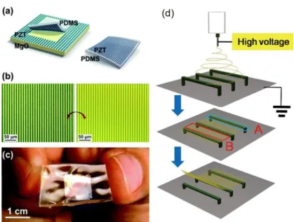
substrates. (a), A high-quality crystalline PZT was firstly deposited on an MgO host substrate, which was subsequently etched, and then PZT nanoribbons were transferred onto flexible plastic substrate using a PDMS stamp. (b), Optical micrograph of PZT ribbons on MgO substrate before transfer, and PZT ribbons on PDMS after transfer printing. (c), Photograph
of a flexible PZT generator. Reprinted from Ref [76, 130]. (d), Schematic diagram of the process for fabricating a PZT textile using electrospinning. Reprinted from Ref [129]. ... 18 Figure 2.7: (a), The wurtzite structure model of ZnO. (b), Schematic diagrams showing the
piezoelectric effect in a tetrahedrally coordinated cation–anion unit. Reprinted from Ref [133]. ... 19 Figure 2.8: Wearable ZnO generator. (a), 3D Schematic diagram depicting the structure of a hybrid-fiber nanogenerator. (b), Image of the experimental setup. (c), Open-circuit output voltage and short-circuit output current density of a fiber device under a strain of ∼ 0.1%. Reprinted from Ref [51]. ... 20 Figure 3.1 : The probe-type ultrasonicator (Fisher Scientific Inc.) ... 26 Figure 3.2: (a) Photo of the electrospinning setup. (b), Schematic of the electrospinning. Reprinted
from Ref [139]. ... 28 Figure 3.3: The design of piezoelectric planar generators ... 28 Figure 3.4: Assembly of the fiber preform ... 30 Figure 3.5: The fiber drawing process. (a), image of the fiber drawing tower. (b), image of the fiber
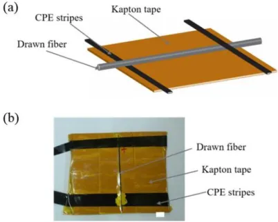
preform cross-section. The blue scale bar is of ~ 1 cm. (c), image of the clamp tractor. (d), schematic of the fiber cross-section. The preform is fabricated by co-rolling electrospun polyvinylidene fluoride (PVDF) mat and C-LDPE film around a polycarbonate tube (PC tube). ... 30 Figure 3.6 : (a) Schematic diagram and (b) Image of the piezoelectric fiber generator. ... 31 Figure 3.7: (a), The loom and a fabricated textile integrated with piezoelectric fibers. The scale bar
is ~ 6 cm. (b), The piezoelectric textile generators. The scale bar is ~5 cm. (c), The image of the piezoelectric fiber. The scale bar is ~ 1 cm. (d) Schematic of the electrodes connection (connected in series) at one fiber end. ... 32 Figure 3.8: The experimental setup for the electrical characterization in (a) bent state and (b)
released state. ... 35 Figure 4.1: (a) Schematic of a fiber drawing process. (b) Schematic of the multilayer structure in
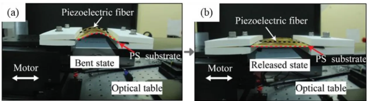
the preform electrodes). Inset: the magnified view of a multilayer structure. (e) A spool of a piezoelectric fiber. (f) SEM images of the CNT/PVDF electrospun mats at different magnifications. (g) Photo of a cross section of the piezoelectric fiber with a diameter of ~ 300 𝜇m (drawn using 5 kV voltage on the preform electrodes). Inset: the magnified view of a multilayer structure. (h) A piezoelectric fiber wrapped on a pencil. ... 43 Figure 4.2: (a) Schematic and a photo (b) of a BTO-PVDF fiber test cell. (c) Fiber in the bent and
released states. ... 44 Figure 4.3: Schematics of the charge separation mechanism in the drawn fibers. (a) All dipoles are
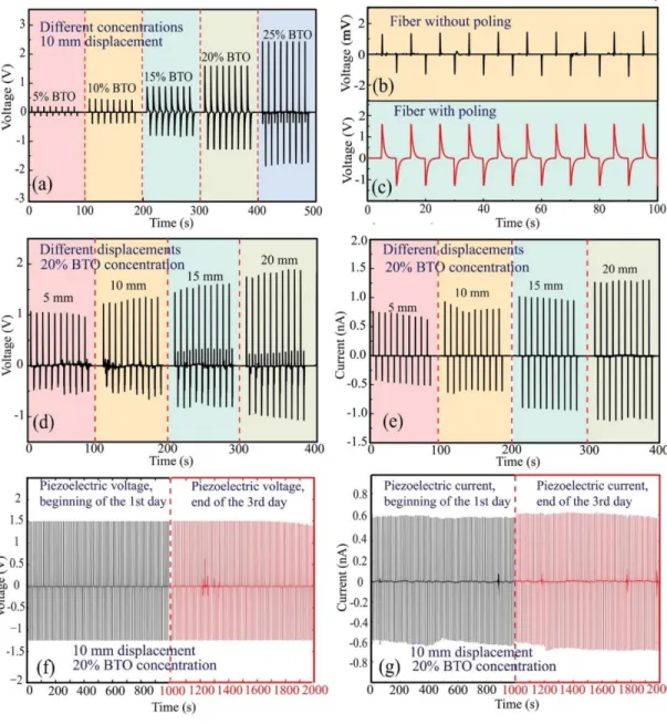
oriented in the direction of the local electric fields during electric poling (no bending). When mechanical strain is applied along the device by bending, the polarization density is changed and the electrons are forced to flow from one electrode to the other, thus generating voltage differential. (b) A schematic of a piezoelectric fiber in the bent state. The piezoelectric fiber was attached to a plane PS substrate and covered with Kapton tape in order to induce a uniform strain during bending. (c) The open-circuit voltage and short-circuit current of the piezoelectric fiber during the bend and release actions. The insert image shows the equivalent circuit of the piezoelectric fiber connected to a voltmeter or a current meter. The piezoelectric fiber is modeled as a capacitor 𝐶𝑓, the voltmeter is modeled as a resistor 𝑅𝑣 and the fiber resistance is 𝑅𝑓. The black line represents the measured output signals during the bend and release state. The red squares represent the modeled results during the bent and released state. ... 46 Figure 4.4: (a) Open-circuit voltage generated by a 10 cm long BTO-PVDF fiber with the BTO
concentration of 5, 10, 15, 20, and 25 wt% subjected to a 1-cm displacement. (b-c) Comparison of the piezoelectric voltages generated by the poled BTO-PVDF fiber generator and the unpoled one. (d) and (e) show the open-circuit output voltage and short-circuit current generated by a 10 cm-long BTO-PVDF fiber generator (20 wt% BTO in the BTO-PVDF composite) when its moving end is displaced by 5, 10, 15, and 20 mm. (f-g) A durability test for the 10 cm long BTO-PVDF fiber (20 wt% BTO in BTO-PVDF composite) by continuously repeating 1 cm amplitude bend-release movements for 3 days. The open-circuit
voltage and short-circuit current generated in a 1000 s period at the beginning of the first day (f) and at the end of the third day (g) are shown. ... 49 Figure 4.5: (a) and (b) show the open-circuit voltage and the short-circuit current generated by a
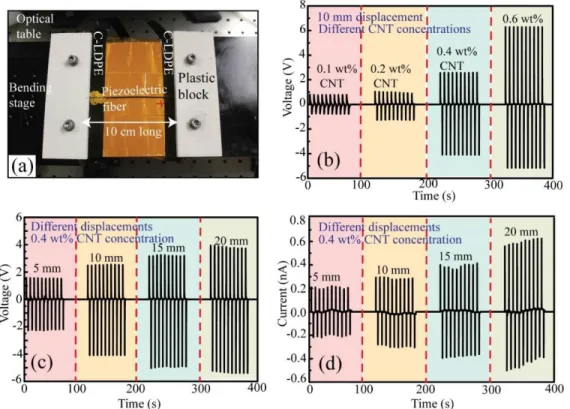
10 cm-long PZT-PVDF fiber generator (20 wt% PZT in the PZT-PVDF composite), when its moving end is displaced by 10 mm. ... 50 Figure 4.6 : (a) Photo of a CNT/PVDF fiber generator. (b) Open-circuit voltage of a 10-cm long
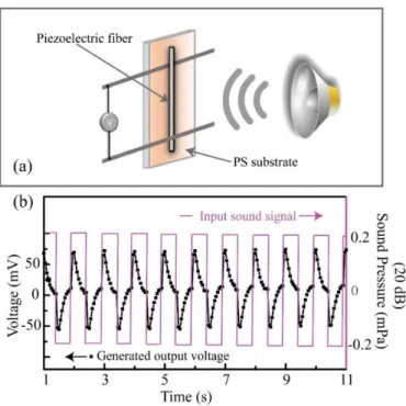
CNT-PVDF fiber generators with CNT concentrations of 0.1, 0.2, 0.4 and 0.6 wt% under 10 mm displacement. (c) and (d) show the open-circuit voltage and short-circuit current of a 10-cm long CNT-PVDF fiber (CNT concentration: 0.4 wt%), when the moving end of the fiber was displaced by 5, 10, 15, 20 mm. ... 51 Figure 4.7 : (a) Schematics of the experimental setup. (b) The sound wave (Red) and the output
voltage from the CNT/PVDF fiber actuated by the sound wave. ... 52 Figure 4.8 : (a) The output voltage generated by the CNT/PVDF fiber at the frequencies of the
actuating sound wave of 1 Hz, 2 Hz and 4 Hz for SPL of ~ 20 dB. (b) The square of the output voltage of the piezoelectric fiber vs. frequency of the sound wave. In the experiment, we measured 20 pulses, and the value of the mean voltage was calculated by averaging the peak value of the measured pulses. The error bar is calculated by the standard deviation (SD) of the peak value of measured pulses. ... 52 Figure 4.9: (a) Schematic and a photo (b) of experimental setup of the underwater ultrasound
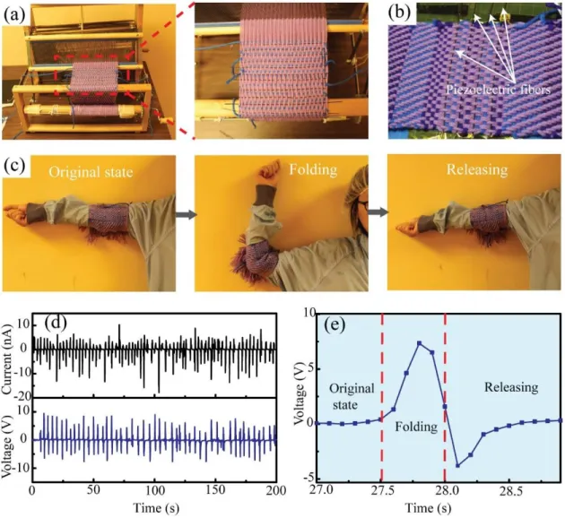
detection using a CNT-PVDF fiber. (c) Piezoelectric voltages generated by the fiber, when the source acoustic powers were 2 W, 4 W and 6 W. (d) The square of the piezoelectric voltage generated by the generator has a linear relationship with the acoustic power. In the experiment, we measured 20 pulses, and the value of the mean voltage was calculated by averaging the peak value of the measured pulses. The error bar is calculated by the standard deviation (SD) of the peak value of measured pulses. ... 54 Figure 4.10: (a) Dobby loom was used to weave piezoelectric fibers into a cotton textile. During
weaving, cotton yarns are used as a warp (longitudinal threads forming the textile base). Piezoelectric fibers are introduced during weaving as a weft by passing them through the warp cotton yarns. (b) A cotton-based textile containing 4 piezoelectric fibers woven using a Dobby
elbow. (d) Open-circuit voltages and short-circuit currents generated by the piezoelectric textile during repeated fold-release motion of the elbow. (e) Open-circuit voltage of the piezoelectric textile in a fold-release elbow action. ... 55 Figure 4.11: (a) Photo of the experimental setup for the in-car test. The piezoelectric fiber textile
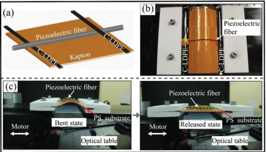
(b) (consisting of fifteen 20 cm-long piezoelectric fibers connected in parallel) was utilized as an automotive microgenerator pad to charge a 10 F capacitor via a bridge rectifier circuit shown in (c). (d) Voltage of the capacitor charged by a piezoelectric textile during driving and stationary state of the vehicle. ... 56 Figure 5.1: Fabrication of the piezoelectric microstructured fibers via drawing of the multimaterial
preforms. (a) Schematic of the fabrication process of a piezoelectric fiber. (b) Schematic of the multilayer structure in the fiber preform and in the microstructured fiber. (c) Photo of a preform cross section. (d) Photo of a cross section of the piezoelectric microstructured fiber. Insert: the magnified view of a multilayer structure. (e) Photo of a piezoelectric microstructured fiber. ... 68 Figure 5.2: Design and performance of the laminated piezoelectric generators. (a) Schematic of a
laminated BTO-PVDF generator that uses an electrospun piezoelectric mat. (b) SEM images of a BTO-PVDF mat at different magnifications. Insert: a magnified image of the BTO-PVDF nanocomposite. (c-d) Testing the laminated piezoelectric generator in its bent and released state. ... 69 Figure 5.3: Performance of the laminated piezoelectric generators. (a) and (b) show the generated
output voltage of the laminated planar generator under bending cycle at different bending displacements (5, 10, 15, and 20 mm). (c) and (d) show the output voltages and currents generated by a BTO-PVDF generator (20 wt.% BTO in the BTO-PVDF composite) when subjected to a 10 mm bending displacement. ... 70 Figure 5.4: Electrical properties of the laminated piezoelectric generators under bending. (a),
Schematic of charge separation in the piezoelectric mat under bending. (b), Equivalent electric circuit of the generator with a resistance load 𝑅𝐿. (c, d), The measured output voltages (c) and
currents (d) generated by a laminated generator (BTO concentration: 20 wt%) under different displacements (𝛥𝑙) compared to the calculated ones (red lines) using Eq. (6). (e, f), The
relationship between the output voltage (current) and piezoelectric mat width 𝑤 (e), and piezoelectric mat thickness 𝑑𝑝 (f). ... 74 Figure 5.5: Design and working principles of the fiber-based piezoelectric generators. (a),
Schematic of a BTO-PVDF fiber-based generator. (b), Setup for testing of microstructured fiber generator. (c), Measured voltage response of the piezoelectric fiber under cycling bending at 0.1 Hz. The top and bottom insets show photographs of the fiber during bending and release, respectively. (d), When mechanical strain is applied along the fiber by bending, the polarization density of the BTO-PVDF layer is changed and the electrons are forced to flow from one electrode to the other, thus generating voltage differential. (e, f), The open-circuit voltage (e) and the short-open-circuit current (f) of the piezoelectric fiber during the bend and release actions. Relaxation of the short circuit current and open circuit voltage on time can be described as single exponential decays with two distinct time constants (red curve fits). ... 77 Figure 5.6: Performance of the piezoelectric microstructured fibers. (a) and (b) show the generated
output voltage of the fiber-based generator under bending cycle at different bending displacements (5, 10, 15, and 20 mm). (c) and (d) show the output voltages and currents generated by a 10 cm-long PZT-PVDF fiber generator (20 wt.% PZT in the PZT-PVDF composite) when subjected to a 10 mm bending displacement. ... 79 Figure 5.7: Potential applications of the piezoelectric fiber generators. (a, b), A cotton-based textile
containing piezoelectric fibers woven using a Dobby loom. (c), Electrical properties of the piezoelectric textile actuated by the human hand tapping. (d), Open-circuit voltages of the piezoelectric textile in a hand tapping-releasing actions. (e), Open-circuit voltages and short-circuit currents generated by the piezoelectric textile during repeated hand tap-release motions. (f, g), Piezoelectric fibers implanted on the airplane wing (f) and the airplane body (g). (h), Open-circuit voltages generated by the piezoelectric fibers during rotation of the airplane propeller. (i), Open-circuit voltages generated by the vibrations induced by the airplane motor operation with the motor speeds set at zero, 1/4, 1/2, 3/4 of its maximum speed. ... 81 Figure 5.8 : Open-circuit voltage generated by the laminated BTO-PVDF generators with the BTO
(20 wt% BTO) generator to that of the unpoled one. ... 84 Figure 5.10 : A durability test was carried out for the laminated BTO-PVDF generator (20 wt%
BTO) by continuously repeating the bend-release test for 3 days. In each bend-release motion, the moving end of the generator was displaced by 10 mm. The open-circuit voltage and short-circuit current generated in a 1000 s period at the beginning of in the first day and at the end of the third day are shown. Overall, 25920 bend/release cycles were performed during 3 days. ... 84 Figure 5.11 : Open-circuit voltage generated by BTO-PVDF microstructured fiber with the BTO
concentration of 5, 10, 15, 20, and 25 wt%. ... 85 Figure 5.12 : Comparison of the open-circuit voltages generated by the poled BTO-PVDF
microstructured fiber and the unpoled one. ... 86 Figure 5.13 : A durability test was carried out for the BTO-PVDF microstructured fiber (20 wt%
BTO in BTO-PVDF composite) by continuously repeating the bend-release test for 3 days. The open-circuit voltage and short-circuit current generated in a 1000 s period at the beginning of the first day and at the end of the third day are shown. ... 87 Figure 5.14 : FTIR spectra of BTO-PVDF electrospun mats at different BTO concentrations .... 88 Figure 5.15: The XRD patterns of the PVDF mats featuring different BTO concentrations ... 89 Figure 5.16: Strain calculation in the laminated piezoelectric generators under bending. ... 91 Figure 5.17: Schematic diagram of mechanics model for the planar piezoelectric generators under
bending ... 92 Figure 6.1: Photos of the drawn fiber (when the BTO concertation is higher than 30%). ... 94 Figure 6.2: Processes commonly employed to obtain piezoelectric PVDF films. ... 97 Figure 6.3 : (a), The fiber preform was placed into the furnace of the draw tower. (b), The preform
electrode was connected to the copper wire. ... 98 Figure 6.4 : (a), The measured output voltage and current signals of the planar device with 20 wt%
BTO/PVDF in the forward connection during the periodic bending and unbending motions. (b), The output voltage and current signals generated in the reverse connection. ... 99
Figure 6.5 : (a), The measured output voltage and current signals of the piezoelectric fiber of 20 wt% BTO/PVDF in the forward connection during the periodic bending and unbending motions. (b), The output voltage and current signals generated in the reverse connection. 100
𝐶𝑓 Fiber capacitance
𝑑𝑒 Thickness of the electrode layer 𝑑𝑝 Thickness of the piezoelectric mat 𝑑31 The piezoelectric coefficient 𝐼𝑠𝑐(𝑡) Short-circuit current
𝑙 The length of a planar generator 𝑅𝑒 Single electrode resistance
𝑅𝑓 The resistance of in-fiber electrodes 𝑅𝐿 Resistance of the load
𝑉𝑜𝑐(𝑡) Open-circuit voltage 𝑤 Width of a planar generator
𝑌𝑝 Young’s modulus of the piezoelectric material 𝑍𝑓 The fiber impedance
𝜏0 Time constant
𝜏𝑐𝑜 Time constant for open-circuit voltage equilibration 𝜏𝑠𝑐 Time constant for short-circuit current equilibration 𝜀 The strain
ϵ𝑝 The complex effective dielectric constant of BTO suspension in the PVDF matrix ϵ𝐵𝑇𝑂 The complex dielectric constants of the pure bulk BTO
ϵ𝑃𝑉𝐷𝐹 The complex dielectric constants of the pure bulk PVDF 𝛥𝑙 The stage displacement
∆𝑄 Surface charges induced on the electrode BTO Barium titanate
CB Carbon black CNT Carbon nanotubes
C-LDPE Carbon filled low density polyethylene DMF Dimethylformamide
FT-IR Fourier-transform infrared spectroscopy LDPE Low density polyethylene
LED Light emitting diode
ICPs Intrinsically conductive polymers IMDs Implantable medical devices MWCNT Multiwalled- carbon nanotubes NFES Near Field Electrospinning NPs Nanoparticles NWs Nanowires PC Polycarbonate PE Polyethylene PP Polypropylene PS Polystyrene PVDF Polyvinylidene fluoride PZT Lead zirconate titanate SD Standard deviation
SEM Scanning electron microscopy SPL Sound pressure level
VR Virtual-reality XRD X-ray diffraction
In the past decades, the invention of electronic devices [1, 2], the internet, wireless communication [3, 4], etc., have completely changed the world and deeply affected our daily life. The rapid advancements in nanotechnology [5, 6] and micro-/nanofabrication techniques [7-10], enabled the miniaturization of electronic devices, making them portable and convenient. Moreover, tremendous effort was spent to integrate electronic devices into various kinds of textiles, garments, fabrics, thus making them wearable. The first commercialized wearable electronics, Apparel ICD+, were released in 2000 by Industrial Clothing Design Plus [11]. The commercialization of these products triggered a slew of investigations into various wearable electronics, including on-garment displays [11], virtual-reality (VR) devices [12, 13], wearable medical/clinic sensors and monitors [14-16], and smart accessories [17-19], some of which have already been successfully commercialized, such as VR headsets, Google glasses, and Apple watches.
While mobile technologies have advanced rapidly over the past 20 years, the development of power sources has lagged considerably [20]. Now most of existing portable electronics are powered by commercial batteries, mostly rechargeable lithium-ion batteries (LIB) [21]. These batteries are generally heavy, rigid, and require outlets for recharging, which somehow impedes the development and miniaturization of wearable electronics. An alternative approach is to harvest energy from the ambient environment [22]. Solar and thermal energies may be the most common and accessible sources of energy that one can harvest from environmental surroundings; however, utilization of these types of energy is generally limited by the environment of the users. In contrast, harvesting electricity from mechanical movements is more reliable, since mechanical energy is a resource that is largely abundant in our daily life with various energy scales and types such as walking [23], mechanical vibrations [24-26], flowing air and water [27, 28], eye blinking [29, 30] and muscle stretching [31].
In 1880, researchers discovered that piezoelectric materials that operated based on the ‘piezoelectric effect’ [32-34] could convert a sufficient part of mechanical energy into electricity. Since then, extensive effort has been put into this field and a variety of piezoelectric materials have been investigated, including natural quartz crystals [35, 36], mechanically flexible piezoelectric polymers [37], exotic and efficient ceramics [38], and other complex composites. Based on these piezoelectric materials, a range of energy harvesting and conversion devices have been proposed,
such as the bulk structures that can be used to dampen vibrations [39], piezoelectric nanowire-based generators for energy harvesting [40, 41], as well as micro-scale actuators fabricated via MEMS process [42-44].
Among all types of piezoelectric generators, perhaps the most promising ones are the piezoelectric fiber-based generators [45-49]. Technically, the advancement of nanotechnology has made it feasible to integrate piezoelectric structures on the surface or the inside of the individual fiber [50-52], which typically has a size from several to tens of microns. These fibers have high energy conversion efficiency, and are capable of harvesting power from small movements [51]. Mechanically, they can be folded, bent, twisted, or stretched while maintaining their electrical properties [53]. Due to their excellent mechanical robustness and flexibility, these fibers could be directly integrated into large-area textiles and fabrics using conventional weaving looms or knitting machines. The as-fabricated ‘piezoelectric garments’ could power on-body electronic systems such as wireless communication networks [54], implantable medical devices (IMDs) [55], and on-garment displays [11], to name a few.
Apart from their wearable applications, the piezoelectric fibers are particularly suitable for the applications in the areas of remote sensing, military industries [56] as well as automotive and aerospace industries [57]. For instance, the piezoelectric fibers could be used as the ultrasensitive sensor for the stand-off sound detection, which opens various possibilities in sensing and defense applications [58]. Moreover, their unique fiber-form-factor allows piezoelectric fibers to be placed/hidden into areas that are not easily accessible such as deep-water, forests, and deep-snow [52]. In a moving vehicle or airplane, piezoelectric fibers harvesting energy from a rotating propeller or other mechanical vibrations could power wireless devices implanted on the surface of the vehicle or airplane [59, 60].
In principle, by engineering the fiber structure and optimizing the fabrication conditions, the piezoelectric functionalities mentioned above could be achieved using a single fiber. Such fibers could be naturally integrated into cotton yarns or textiles, using cost-effective textile production processes. However, there are currently only a few reports regarding to such piezoelectric fibers, due to technical complexity of integration of various sub-components with different functionalities into a textile fiber [61]. In recent reports, most of the existing piezoelectric fibers are fabricated either by growing piezoelectric nanostructures along a conductive filament or by extruding
performance and applications of the existing piezoelectric fibers are limited by their simple fiber geometries, large diameter, poor mechanical reliability and relatively low piezoelectric response.
Multimaterial preform-to-fiber drawing methods [66], on the other hand, present unique opportunities for drawing flexible piezoelectric fibers of extended lengths. Most importantly, these methods allow for the fabrication of piezoelectric fibers with complex architectures that integrate a variety of sub-components with different functionalities [67, 68]. In this thesis, we report micro- and nanostructured piezoelectric fibers fabricated via heating and drawings of multimaterial preforms. The fibers feature a hollow polycarbonate (PC) core surrounded by a spiral multilayer cladding consisting of alternating piezoelectric PVDF-based nanocomposite layers and conductive layers (carbon-filled low-density polyethylene).
To achieve a successful fiber drawing process, we need to follow several general guidelines. The key challenge of fiber drawing is to maintain the geometry of the fiber while reducing its cross-sectional dimensions. Throughout our many experiments, the multimaterial preforms tended to break-up into filaments during the drawing process. This is because the drawing process decreases the feature size and viscosity, thus naturally causing flow instabilities and finally, facilitating fiber breakage. To achieve a stable drawing, the materials used must be carefully selected, ensuring that they are thermally and mechanically compatible. The materials used for this process must meet the following requirements [66, 67]:
First, at least one of the fiber materials should be amorphous, so that it can withstand the mechanical stress in the fiber drawing process.
In addition, all the materials should flow into a viscous state when heated above the softening temperature.
Also, all the materials used should exhibit good adhesion/wetting in their viscous and solid states without cracking, even when subjected to the rapid heating/cooling rate.
Finally, to obtain fibers with high piezoelectric properties, at least one of the fiber materials should have a high piezoelectric coefficient.
Chapter 2 begins with a literature review of wearable piezoelectric generators. The wearable power generators made of piezoelectric polymers, ceramics or composites are reviewed with their advantages and limitations discussed.
Chapter 3 provides the methodology in the R&D of piezoelectric micro-/nanostructured fibers, which includes the preparation of the piezoelectric nanocomposites via electrospinning, assembly of the planar piezoelectric generators, fabrication of the piezoelectric fibers via preform heating and drawing, fabrication of piezoelectric textiles/fabrics via loom-weaving, as well as characterization of the corresponding piezoelectric fibers and textiles.
Chapter 4 is based on my paper “Piezoelectric Micro- and Nanostructured Fibers Fabricated from Thermoplastic Nanocomposites Using a Fiber Drawing Technique: Comparative Study and Potential Applications” published in ACS Nano (2017). This paper conducts a comparative study of the piezoelectric micro- and nanostructured fibers using the material combinations including BTO-PVDF, PZT-PVDF and CNT-PVDF.
Chapter 5 is based on my paper “Piezoelectric Microstructured Fibers via Drawing of Multimaterial Preforms” published in Scientific Reports (2017). This paper demonstrates the fabrication and characterization of the piezoelectric generators using BTO-polyvinylidene and carbon-loaded-polyethylene in stripe forms as well as in fiber forms.
To conclude, I present a general discussion of results achieved so far and elaborate future research perspectives.
The electronic products of the future generation place a great demand for the R&D of novel energy harvesting devices that are wearable [40]. To date, significant effort has been put into the R&D of piezoelectric fiber-based generators as they are soft, flexible and comfortable to wearers. In principle, such piezoelectric fibers can be such designed that they feature both a very high energy conversion efficiency, close to that of piezoelectric ceramics, and a very high mechanical flexibility, close to that of piezoelectric polymers. Hence, it is of great importance to study the fiber-based power generators that are able to convert a significant part of the kinetic energy from ambient environment or human movements.
In this Chapter, we begin with a brief introduction of the working principles of the piezoelectric generators. Then, we review the wearable piezoelectric generators according to the different types of the piezoelectric materials. Finally, the motivation and objectives of my doctoral project will be presented.
2.1 The working principles of the piezoelectric generators
When the mechanical force is applied to the piezoelectric generators, electrical pulses of voltage (current) could be generated. To explain this phenomenon, we need to study the working principles and the effective electric model of the piezoelectric generators. As shown in Fig. 2.1, the piezoelectric generator could be considered as a capacitor that consists of electric diploes dispersing in the matrix of the dielectric material [37, 69]. After electrical poling, the electric dipoles in the piezoelectric material could be aligned in the same direction. Even after the electric field is removed, the permanent polarization remains in the piezoelectric material. The electric field of the dipoles will induce the surface charge −Q at the top electrode and the +Q at the bottom electrode. When the mechanical stress is applied to the piezoelectric generator, the polarization density of the piezoelectric material will change, which will induce the change of the surface charge (∓Q) at the top and bottom electrode. In response to that, the electrons in the external circuit will force to move from one electrode to the other electrode, generating a piezoelectric potential.
The equivalent electric circuit in the measurement could be illustrated as Fig. 2.1b. In the case of a planar piezoelectric film of length 𝑙, width 𝑤, thickness 𝑑𝑝, and dielectric constant ϵ𝑝, the
generator capacitance is 𝐶 =ϵ𝑝𝜖0𝑙𝑤
𝑑𝑝 . And 𝑅𝐿 is the resistance of the load in the electric circuit. The
resistance of the electrode resistance that covers the piezoelectric film is 𝑅𝑒 = 𝜌 𝑙
𝑤𝑑𝑒, where 𝑑𝑒 is
the electrode thickness and 𝜌 is the bulk resistivity of the electrode material. Using standard analysis of this RC electric circuits, we can write the equations that govern time dynamics of the capacitor discharges:
𝑞
𝐶+ 𝑞̇𝑅𝐿 = 0 (1)
𝑞|𝑡=0= ∆Q (2) We consider the resistance of the voltmeter 𝑅𝑉 = ∞ and the resistance of the currentmeter 𝑅𝑐 = 0. Thus, for the open-circuit voltage measurement, we consider 𝑅𝐿~𝑅𝑉; for the short circuit
current measurement, we consider 𝑅𝐿~𝑅𝑒. Finally, we can find simple solutions that satisfy both (1) and initial conditions (2) in the following expressions for the open circuit voltage 𝑉𝑜𝑐(𝑡) and the short circuit current 𝐼𝑠𝑐(𝑡) :
Open-circuit voltage: 𝑉𝑜𝑐(𝑡) =∆𝑄 𝐶 𝑒 − 𝑡 𝐶𝑅𝑣 𝑉𝑚𝑎𝑥𝑜𝑐 = 𝑉𝑜𝑐(0) = ∆𝑄 𝐶 (3) Short-circuit current: 𝐼𝑠𝑐(𝑡) = ∆𝑄 𝐶𝑅𝑒𝑒 − 𝑡 𝐶𝑅𝑒 𝐼𝑚𝑎𝑥𝑠𝑐 = 𝐼𝑠𝑐(0) = ∆𝑄 𝐶𝑅𝑒 (4)
According to the literature[70], fixed charges ∆𝑄 induced on the surface of a piezoelectric film of length 𝑙 can be calculated as:
∆𝑄 = 𝑑𝑌𝑝𝜀𝑤 ∙ 𝑙 (5) where 𝑑 is the piezoelectric coefficient of a piezoelectric film, 𝑌𝑝 is the Young’s modulus of the piezoelectric material, 𝑤 is the width of the piezoelectric mat, and 𝜀 is the applied strain. Thus, we can then conclude that the peak open circuit voltage and open circuit currents is proportional to the applied strain and piezoelectric film thickness:
|𝑉𝑚𝑎𝑥𝑜𝑐 | = 𝜀
𝑑𝑌𝑝𝑤𝑙
𝐶 = 𝜀𝑑𝑝 𝑑𝑌𝑝
Figure 2.1: Design and working principles of the piezoelectric generators. (a), Schematic illustration of the application of the stress onto a poled piezoelectric generator (e.g. the BaTiO3 generator). In the initial state (after electrical poling), the electric dipoles maintain the permanent polarization. When mechanical stress is applied onto the piezoelectric generator, the polarization density of the piezoelectric film is changed and the electrons are forced to flow from one electrode to the other, thus generating a piezoelectric potential. (b), The equivalent electric circuit in the measurement. The piezoelectric generator is considered as a capacitor, while 𝑅𝐿 is the resistance of the load in the electric circuit.
2.2 The wearable piezoelectric generators
One of the most important concerns for the R&D of wearable piezoelectric generators is the choice of the piezoelectric materials utilized and the possibility to preserve their piezoelectric performance [61], while maintaining their durability, safety, and stability when integrated into flexible systems. In this regard, the following review of wearable piezoelectric generators including flexible planar and fiber devices, will be given based on the different types of piezoelectric materials.
2.2.1 Wearable piezoelectric generators based on piezoelectric polymers
The piezoelectric polymers are attractive due to their ease of production, high chemical resistance, superior flexibility, and excellent mechanical robustness [37]. One of the most widely used piezoelectric polymers is poly(vinylidene fluoride) [37] [71], which is also known as PVDF. Depending on the different stereochemical structures, the PVDF polymer has the most common three forms [37], namely 𝛼 (TGTG'), 𝛽 (TTTT), 𝛾 (TTTGTTTG') phase respectivley (Fig. 2.2).
Commerical PVDF generally has the 𝛼 phase, which may be obtained by the melt-extrusion or the film-casting [37]. In the 𝛼 phase, the electric diploes are antiparallel along the chain axes, thus cancelling each other. Therefore, 𝛼 phase is a non-polar phase. The 𝛽 phase is most highly polar phase, whose unit cell of the lattice consists two chains in the TTTT conformation. And the electric dipoles in the 𝛽 phase are normal to the chain axes. The 𝛽 phase PVDF could be obtained by stretching the 𝛼 phase PVDF togther with electrical poling. In the γ phase, the polymer chains are in the TTTGTTTG' conformation, and thus, γ phase has lower polarity when compared with 𝛽 phase. Consequently, the 𝛽 phase PVDF is the most desirable phase for generating piezoelectricity [69]. To date, the considerable amount of work has been carried out, aimed at the production of high 𝛽-phase PVDF and their integration into wearable structures for energy harvesting. The first report of wearable PVDF piezoelectric generators was proposed by Kymissis et al.[72], in which 8 layers of 28 𝜇m thick PVDF films were stacked in a sneaker. In the fabrication process, the polar 𝛽-phase was achieved via stretching the PVDF films, followed by an electrical poling. One of the major shortcomings of such generators is the low output power, due to their small active area and low fraction of polar 𝛽 phase. To address this issue, PVDF nanofibers were produced and then integrated into various wearable generators. PVDF nanofibers are generally more attractive towards bulk PVDF as they have higher energy conversion efficiencies, due to their large surface areas. Recently, a wide range of techniques have been developed to fabricate high performance PVDF nanofibers.
Figure 2.2: Schematic description of the 𝛼 (TGTG'), 𝛽 (TTTT) and 𝛾 (TTTGTTTG') phase of PVDF. (a), 𝛼 phase. (b), 𝛽 phase. Reprinted from Ref [67].
PVDF nanofibers. In a typical electrospinning process, a polymer solution is first pumped into a syringe needle that is connected to a high voltage (typically 10-30 kV) power supply. The polymer solution charged by high voltage is then ejected from the needle, and formed a liquid jet. As the solvent evaporates, polymer micro- or nanofibers are produced and collected by a fiber collector. The distance between the needle and the collector is typically in the range of 5-15 cm [73, 74]. And the ordered 𝛽 phase is induced by the combination of mechanical stretching and electrical poling during electrospinning process [73]. To date, various wearable piezoelectric generators have been fabricated based on electrospun PVDF nanofibers. For example, Zeng et al.[75] demonstrated an all-fiber piezoelectric generator that was fabricated by sandwiching a fabric of electrospun PVDF-NaNbO3 nanofibers between two fabric electrodes. This generator with an area of 2.5×2.5 cm2 was able to produce an open-circuit voltage up to 3.4 V during a cyclic compression test (frequency: 1 Hz) with a maximum pressure of 0.2 MPa. Moreover, this generator retained its excellent performance even after 1,000,000 compression–recovery cycles.
It is worth noting that the alignment of nanofibers considerably influences their piezoelectric performance [55, 76]. An electrospun mat with all the nanofibers oriented neatly along their own dipole direction shows significantly improved energy generation efficiency. Also note that a good alignment of electrospun nanofibers can be achieved by the near-field electrospinning process (NFES) [77]. In a NFES, the distance between the collector and the needle is set in the range of millimeter scale, and the applied voltage is thus reduced to ~1 kV. Using this technique, various piezoelectric generators based on aligned PVDF nanofibers have been proposed [78-82]. For instance, Fuh et al.[83] reported the fabrication of a wearable piezoelectric generator consisting of 20, 000 rows of well-aligned PVDF nanofibers (Fig. 2.3a). This piezoelectric generator (3.5×1 cm2) is able to create an open-circuit of 0.8 V with finger folding-releasing actions. Recently, the same group reported a 3-dimensional (3D) piezoelectric device by vertically stacking the electrospun PVDF nanoarrays [84]. Owing to the novel structure, this device could generate open-circuit voltages and short-open-circuit currents up to ~1.2 V and 60 nA respectively. Note that in the fabrication of the piezoelectric generators mentioned above, the electrospun nanofibers are usually physically deposited or assembled on the top of flexible substrates. Thus, these generators typically suffer from poor stability due to the weak binding force between piezoelectric nanofibers and
substrates. Besides, some generators need to attach metal electrodes which limits their applications and lifetime.
Other spinning techniques such as wet-spinning [85] or melting-spinning [86] were also investigated for the fabrication of piezoelectric polymer fibers. As an example, Lund et al. fabricate melt-spun PVDF fibers (Fig. 2.3c) that adopt carbon-black filled polyethylene (CB-PE) as the electrodes [63, 87-89]. Typically, the polymer fibers fabricated by spinning techniques feature a core-sheath structure, in which a conductive filament serves as the core, and a piezoelectric polymer layer constitutes the sheath [90]. Besides, the as-spun fibers generally require an additional conductive coating as an external electrode. Such fibers may have reliability issues due to surface abrasion and repeated mechanical deformations.
Apart from traditional spinning techniques, fiber drawing [67, 91] is another efficient technique that can be used to produce piezoelectric polymer fibers. In this method, kilometer-long functional fibers are thermally drawn from a geometrically complex multimaterial fiber preform with a length of tens of centimeters [92]. In the fiber drawing process, firstly a fiber preform is assembled using a variety of materials such as polymers, metals, glass or other functional components and sub-components. Then, the preform is placed in a vertical furnace tower and heated above the transition temperature. Upon heating, extended lengths of fiber with controlled diameter are thermally drawn from the softened preforms. The resultant fiber generally maintains the perform structure but with a much smaller cross-section dimension, which is not achievable through the use of the traditional spinning technique. Kanik et al. [93] fabricated piezoelectric PVDF micro- and nanoribbons using an iterative size reduction technique based on thermal fiber drawing (Fig. 2.3b). In order to obtain spontaneously polar phase PVDF, the fiber needs to redraw several times. At this point, the fabrication process would be tedious and time-consuming.
In addition to PVDF, other piezoelectric polymers have been investigated for the application in wearable generators. For example, P(VDF-trifluoroethylene) [P(VDF-TrFE)] [94-96] is known for its higher piezoelectric constant than that of PVDF due to the highly ordered crystalline structure by aligning CF2 dipoles in preferable directions. Various piezoelectric devices based on P(VDF-TrFE) have been fabricated using a range of techniques including electrospinning, melt-spinning, and fiber drawing [66, 97-99]. Egusa et al. [66] demonstrated a polycarbonate fiber containing P(VDF-TrFE) as the piezoelectric element and indium filaments as the electrodes (Fig.
P(VDF-TrFE) was assembled with indium filaments within a poly(carbonate) cladding to produce a fiber preform that was subsequently drawn by a polymer-fiber drawing tower. The as-drawn fiber was reported to generate an audible sound between 7 kHz and 15 kHz with a driving voltage of 5 V. However, P(VDF-TrFE) copolymers are much more expensive than PVDF.
Table 2.1 summarizes the different types of wearable piezoelectric generators based on piezoelectric polymers. Generally speaking, the piezoelectric polymer generators usually have a long-time lifespan due to the mechanical robustness of the piezoelectric polymer. However, such generators typically suffer from the following shortcomings: First of all, most of the existing piezoelectric generators need to attach metal electrodes which limits their applications and lifetime. The metal electrodes under repeated mechanical deformations generally result in fatigue and fracture. Second, in the most of the existing piezoelectric generators, the piezoelectric fibers/mats are usually physically embedded or deposited onto flexible substrates. These generators suffer from poor stability due to the weak binding force between piezoelectric polymers and substrates. Finally, the output power of some polymer generators is relatively low and is insufficient for practical applications.
Figure 2.3: Summary of the piezoelectric polymer fibers. (a), Schematic of the direct-write, and electrical poling PVDF fibers via NFES. Reprinted from Ref [83]. (b), Schematic of the fabrication
of the piezoelectric PVDF micro- and nanoribbons using iterative size reduction technique. Reprinted from Ref [93]. (c), Cross-section of the PVDF fiber that uses carbon-black (CB)/polypropylene (PP) as the core. Reprinted from Ref [63]. (d), Schematic of the fabrication of the piezoelectric microstructured PVDF fiber using fiber drawing technique. Reprinted from Ref [66].
Table 2.1: The comparison between the different types of wearable piezoelectric generators based on piezoelectric polymers Type of piezoelectric materials Photo (diagram) of the generators
Applied force type and area Generated electrical signals Comments Ref PVDF Applied cyclic pressure of 0.2 MPa; 2.5×2.5×0.2 cm 3.2 V; 4.2 μA Poor stability [75] Stretching-releasing deformations at a strain of 0.5%; 3.5 cm × 1 cm×2 μm 4 V; 390 nA Use metallic electrodes [83] Bending-releasing deformations at a strain of 0.05%; Fiber length of 1 mm, fiber diameter of ~200 μm 25 mV; 7.5 nA Poor stability [81] Wing vibration at 0.5 Hz; Fiber length of up to 20 mm 0.2 V No reports about the output currents [100 ]
Finger tapping-releasing actions; 50 μm thick ~2.5 μA; ~5V The fabrication process is complex [93] PVDF-TrFE
Applied cyclic load of 1 mN; Fiber length of ~80 μm ~0.3 mV No reports about the output currents [97] Applied cyclic pressure of 160 kPa; Fiber length of 10 mm ~2.6 V ~15 nA The fiber has a simple core-sheath structure [98]
2.2.2 Wearable piezoelectric generators based on piezoelectric ceramics
The wearable generators based on piezoelectric ceramics have drawn a lot of interest due to their high energy conversion efficiency and their capacity to harvest energy from small movements [76]. Generally, the piezoelectric ceramics can be divided into two categories [76]: (1) perovskite structured piezoelectric materials, such as barium titanate (BaTiO3) [38, 101], lead zirconate titanate (PZT) [102, 103], potassium niobate [104, 105], and sodium niobate [104, 106]; (2) semiconductor piezoelectric materials, including Zinc oxide (ZnO) [107, 108], zinc sulfide (ZnS) [109], gallium nitride (GaN) [110, 111] and indium nitride (InN) [112]. However, bulk piezoelectric ceramics are rigid, brittle, and thus unsuitable for wearable applications. In order to circumvent this barrier, flexible devices are fabricated by directly using ceramic nanofibers (BaTiO3, PZT) or nanowires (ZnO) grown on flexible substrates (polymers [113], papers [114], fibers [115], or textiles [116]), or by impregnating piezoelectric micro-/nanoparticles into soft polymers [76, 114].
In what follows, I will give a brief review of piezoelectric generators based on perovskite ceramics including BaTiO3 and PZT. Among the advantages of these piezoelectric generators are their low cost, ease of fabrication and high piezoelectric performance.
(1) Barium titanate (BaTiO3)
BaTiO3 is a perovskite crystal, whose structure is schematized in Fig. 2.4a. Each crystal is composed of a small, tetravalent metal ion placed inside a lattice of larger divalent metal ions and O-2. Above a critical temperature, which is known as the “Curie temperature”, each perovskite crystal in the heated ceramic element exhibits a simple cubic symmetry with no dipole moment, as demonstrated in Fig. 2.4a [117]. At temperatures lower than the Curie temperature, each crystal has a tetragonal symmetry and exhibits a dipole moment. If a BaTiO3 tetragonal crystal is placed in a strong DC electric field at a temperature below the Curie temperature, the dipoles will be aligned in the same direction of the electric field. Even after the electric field is removed, the oriented domains maintain the permanent polarization. When the mechanical compression or tension is applied on the BaTiO3, the polarization density in the crystal would change, thus generating a piezoelectric potential. As shown in Fig. 2.4b, compression along the direction of polarization, or tension perpendicular to the direction of polarization, could generate voltage of the same polarity as that of the poling voltage. Tension along the direction of polarization, or compression perpendicular to that direction, would generate a voltage with its polarity opposite to that of the poling voltage (Fig. 2.4b) [117].
Bulk BaTiO3 is brittle and thus can’t be directly used as mechanical energy harvesting materials. Instead, piezoelectric generators based on BaTiO3 are usually fabricated by dispersing BaTiO3 nanoparticles into flexible polymers [70, 114, 118, 119]. For instance, Park et al.[120] demonstrated a planar generator based on BaTiO3 nanoparticles (NPs) and graphitic carbons (Fig. 2.5a). In this work, the BaTiO3 nanoparticles and carbon were dispersed in polydimethylsiloxane (PDMS) solution. After drying, the obtained polymer film is sandwiched between two electrode films into a wearable piezoelectric generator. This wearable device could generate the output voltage of ~1.5 V and current of ~150 nA under a pressure of ∼ 57 kPa. Here graphitic carbons plays multiple roles, such as improving the dispersion of BaTiO3 NPs in the host polymer, as well as reinforcing the stress applied to nanoparticles.
Figure 2.4: (a), Change of unit cell of a BaTiO3 crystal during spontaneous polarization. (b), Reaction of a poled piezoelectric element to applied stimuli. Reprinted from Ref [117].
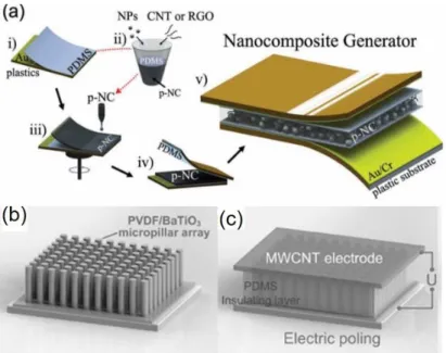
To further improve the piezoelectric response, wearable BaTiO3 generators have been fabricated by combining BaTiO3 nanostructures with piezoelectric polymers. For instance, Zhao et al. [70] reported a flexible generator by dispersing BaTiO3 NPs into the PVDF matrix using the solvent evaporation method. In this device, PVDF not only functions as a binder for BaTiO3 NPs, but also plays a part in generating piezoelectric potential. The highest open-circuit voltage and short-circuit current achieved were 150 V and 1500 nA respectively, while a stress of 10 MPa was applied to the piezoelectric generator. Recently, Chen et al. [121] demonstrated a flexible device by vertically aligning BaTiO3/PVDF micropillar arrays onto parallel multiwall-CNT (MWCNT) electrodes (Fig. 2.5 b,c). This device could generate an enhanced voltage of 13.2 V and a current density of 0.33 μA/cm2, which is more than 7-times larger than that of the pristine PVDF bulk films.
Figure 2.5: Wearable BaTiO3 generators. (a), Schematics of the fabrication process of the BaTiO3- graphitic carbons nanocomposite generator. Reprinted from Ref [120]. (b, c), SEM images of the cross-section of the piezoelectric generator based on BaTiO3/PVDF micropillar arrays. c), A magnified top view of the SEM image of MWCNT layer. Reprinted from Ref [121].
(2) Lead zirconate titanate (PZT)
Similar to barium titanate, lead zirconate titanate (Pb[ZrxTi1-x]O3, PZT) also features a perovskite crystal structure, and can be considered as one of the most promising piezoelectric materials due to its higher piezoelectric coefficient compared to that of other piezoelectric materials [122, 123]. Actually, the piezoelectric coefficient (𝑑33) of bulk poled PZT can be as large
as 289 pm/V, which is ten times higher than that of PVDF [124, 125].
Wearable PZT generators can be fabricated using a scalable transfer printing method. In this approach (Fig. 2.6), high-quality PZT thin films are first grown onto rigid crystal wafers, and then printed onto flexible films of plastic, graphene, or rubber [76]. In this method, a pre-fabricated stamp with the desired features is used to transfer the PZT structures from the rigid wafer to the soft substrate. A conformal contact between the stamp and the substrate enables high fidelity when transferring the material to the surface. The stamp can be made from PDMS, and epoxy, to name a few. Using this method, Kwon et al. [126] fabricated a flexible generator based on PZT nanoribbons. In their work, a good quality crystalline PZT was firstly deposited on a Pt/Ti/SiO2/Si wafer, which was subsequently etched, and then PZT nanoribbons were transferred onto a flexible
to collect electrical signals. The fabricated piezoelectric generators generated a high output voltage of up to ~2V, a current density of ~2.2 μA/cm2, and a power density of ~88 mW/cm3 at an applying force of ~9 N. This method is effective for large-scale assembly of piezoelectric crystalline ceramics onto flexible substrates. The merits are obvious; however, this technique also has drawbacks. For example, the crystallization of PZT typically requires a high temperature (higher than 650ºC) to maximize power generation efficiency, which makes the fabrication process expensive and complex.
Another approach begins with electrospinning PZT into nanofibers, following by assembling or packing the nanofibers with soft polymers. This method involves the steps including preparing precursor solutions, electrospinning and subsequently calcining at suitable temperatures to form highly crystalline PZT nanofibers, and finally assembling PZT nanofibers with soft polymers [127-129]. Chen et al. [127, 128] demonstrated the wearable generators following this route. In their work, PZT nanofibers with a diameter of ~100 nm and a length of ~70-100 μm were prepared by electrospinning the sol-gel of PZT and polyvinylpyrrolidone (PVP). Then, the nanofibers were annealed at 650 ℃ to obtain the perovskite phase. Subsequently, a soft polymer (polydimethylsiloxane, PDMS) was spin-coated on top of the PZT nanofibers. This generator could generate an output voltage of 1.63 V and power of 0.03 µW, under periodic finger press-release actions. Recently, vertically aligned PZT nanowires were prepared by electrospinning [41, 113, 129], and the performance of the as-fabricated piezoelectric generators was greatly improved. Generally, the fabrication of aligned PZT nanowires was performed on multipairs of parallel electrodes using electrospinning (Fig. 2.6d), in which Coulomb force plays a very important role in obtaining parallel nanowires between parallel electrodes [113, 129]. Using this method, Gu et al. [113] demonstrated a wearable generator based on ultra-long PZT nanowire arrays. Such generators with an area of 2.25 cm2 can produce a maximum peak voltage of 198 V for an external load of 100 MΩ and a peak output current of 17.8 μA for an external load of 100 Ω. Moreover, this generator can directly lighten a commercial LED with a working voltage of 1.9 V even without the use of storage circuits.
![Figure 3.2: Schematic of the electrospinning. Reprinted from Ref [139]. 3.1.2 Fabrication of the piezoelectric planar generators](https://thumb-eu.123doks.com/thumbv2/123doknet/2337712.33180/52.918.342.552.105.276/figure-schematic-electrospinning-reprinted-fabrication-piezoelectric-planar-generators.webp)