UNIVERSITÉ DE MONTRÉAL
TRIBO-MECHANICAL AND ELECTRICAL PROPERTIES OF
BORON-CONTAINING COATINGS
JINCHENG QIAN
DÉPARTEMENT DE GÉNIE PHYSIQUE ÉCOLE POLYTECHNIQUE DE MONTRÉAL
THÈSE PRÉSENTÉE EN VUE DE L’OBTENTION DU DIPLÔME DE PHILOSOPHIÆ DOCTOR
(GÉNIE PHYSIQUE) MARS 2015
UNIVERSITÉ DE MONTRÉAL
ÉCOLE POLYTECHNIQUE DE MONTRÉAL
Cette thèse intitulée:
TRIBO-MECHANICAL AND ELECTRICAL PROPERTIES OF
BORON-CONTAINING COATINGS
présentée par : QIAN Jincheng
en vue de l’obtention du diplôme de : Philosophiæ Doctor a été dûment acceptée par le jury d’examen constitué de: M. YELON Arthur, Ph. D., président
Mme KLEMBERG-SAPIEHA Jolanta-Ewa, Doctorat, membre et directrice de recherche M. ZHANG Wenjun, Ph. D., membre et directeur de recherche
M. MARTINU Ludvik, Ph. D., membre et codirecteur de recherche M. WANG Zuankai, Ph. D., membre
M. MEUNIER Jean-Luc, Ph. D., membre externe M. WANG Ning, Ph. D., membre externe
UNIVERSITÉ DE MONTRÉAL
ÉCOLE POLYTECHNIQUE DE MONTRÉAL
Tribo-Mechanical and Electrical Properties of Boron-Containing Coatings
Submitted to
Département de Génie Physique École Polytechnique de Montréal in Partial Fulfillment of the Requirements
for the Degree of Doctor of Philosophy
awarded by École Polytechnique de Montréal for successful completion of the joint programme with
City University of Hong Kong
by
JINCHENG QIAN
DEDICATION
ACKNOWLEDGMENTS
This thesis work resulted from the double-diploma Ph.D. program under cotutelle between City University of Hong Kong and École Polytechnique de Montréal. A lot of people’s efforts helped to initiate this program, and many people helped my work.
First, I would like to thank my four supervisors. Professors Wenjun Zhang and Igor Bello gave me the opportunity of starting my Ph.D. study at CityU. Professors Jolanta Sapieha and Ludvik Martinu brought me the opportunity of joining this double-diploma Ph.D. program and of studying at Polytechnique. I am grateful for all their guidance, patience and support throughout my Ph.D. study. They are always there to help and encourage me when I have difficulties and feel confused. Their attitudes towards research and life influenced me significantly both on professional and personal levels. I am blessed to meet these four great persons in my life.
I would like to extend my gratitude to all the members of COSDAF at CityU and of FCSEL at Polytechnique, particularly to Shrawan Jia, Yan Ce, Chen Zhenhua, Wang Hongen, Liu Chaoping, Karen Ng at COSDAF, to Etienne Bousser, Thomas Schmitt, Oleg Zabeida, Duanjie Li, and Marwan Azzi at FCSEL, and to others I did not mention here. I am thankful to the technicians Felix Wong at COSDAF and Sébastien Chenard and Francis Turcot at FCSEL. I would not finish my projects without your technical support.
I would like to give my special thanks to Prof. Lawrence Li (from MEEM CityU) for providing the magnetron sputtering deposition system and to Dr Zhifeng Zhou for his assistance on the coating deposition. I would like to thank all the co-authors of my papers; I really enjoyed the collaboration.
I would also like to thank Prof J. A. Zapien, Ms. Line Dubé, and Ms. Nathalie M. Pelletier who helped this double-diploma Ph.D. program work.
Last but not least, I sincerely thank my parents and my husband Mr. Zuo Dawei, who have been supporting me all the time. Thank you for all your love, understanding, and company in my life.
RÉSUMÉ
Le développement de nouveaux revêtements protecteurs durs ayant une performance de pointe est très important pour le progrès scientifique relié à de plusieurs domaines industriels. L’application de revêtements protecteurs durs peut augmenter significativement la performance de pièces et composantes, étendre leur durée de vie ainsi que sauver de l’énergie dans maintes industries incluant l’aérospatial, l’automobile, les manufactures et bien d’autres. De plus, la multifonctionnalité des revêtements représente une valeur ajoutée dans d’autres domaines tels que l’optique, la microélectronique, le biomédical, le stockage magnétique de données, etc. Ainsi, les revêtements protecteurs avec des propriétés tribo-mécaniques améliorées et une résistance à la corrosion augmentée sont très en demande.
Les caractéristiques des revêtements peuvent être ajustées en contrôlant leur microstructure sur une échelle répandue dans différents ordres de grandeur. Par exemple, les films avec des nanostructures, comme les super-réseaux, les nanocolonnes et les systèmes nanocomposites, montrent des caractéristiques très distinctes par rapport aux matériaux à une seule phase. Ils montrent des propriétés tribo-mécaniques supérieures grâce à la présence d’interfaces internes rigides et différentes fonctions peuvent être accomplies avec un matériau multi-phase.
Les matériaux contenant du bore ont d’excellentes propriétés mécaniques et des caractéristiques électroniques très intéressantes, ce qui en fait de bons candidats pour les revêtements protecteurs fonctionnels durs. Par exemple, le nitrure de bore cubique (c-BN), le carbure de bore (B1−xCx) et le diborure de titane (TiB2) sont très connus pour leur grande dureté,
leur haute stabilité thermique et leur caractère chimique inerte. Un exemple intéressant est le nitrure de carbure de bore (BCN) qui possède plusieurs propriétés attrayantes grâce à la similarité structurale avec le carbone (graphite et diamant) ainsi que le nitrure de bore (BN en phase hexagonal ou cubique).
L’objectif principal de cette recherche est de développer plus en détail la famille de revêtements contenant du bore, incluant le B1−xCx, le Ti−B−C et le BCN déposés par
pulvérisation magnétron, pour améliorer leur performance sur mesure et obtenir de nouvelles fonctions en contrôlant leur microstructure à l’échelle nanométrique. Leurs propriétés tribo-mécaniques, leur résistance à la corrosion ainsi que leurs propriétés électriques sont étudiées en relation avec la composition et la microstructure, en gardant toujours en mire l’amélioration de
leur performance pour des revêtements multifonctionnels protecteurs par la conception de microstructures.
Premièrement, des revêtements B1−xCx (0 < x < 1) avec des propriétés tribo-mécaniques
adaptées ont été déposées par pulvérisation magnétron en utilisant une cible de graphite et deux de bore. La dureté du revêtement de B1−xCx a été mesurée à 25 GPa, soit la même dureté pour
ceux composé à majorité de bore ou de carbone, alors que le coefficient de friction et le taux d’érosion peuvent être ajustés respectivement de 0,66 à 0,13 et de 6,4×10⁻⁵ mm3/Nm à 1,3×10⁻⁷ mm3/Nm, en changeant la proportion de carbone de 19 % à 76 % atomique. La variation de dureté est étroitement liée à la microstructure alors que le coefficient de friction faible et le taux d’érosion réduit du B0.24C0.76 sont causés par une plus grande proportion de la phase de carbone
amorphe. Aussi, l’application du revêtement B0.81C0.19 améliore significativement la résistance à
la corrosion de l’acier M2, indiqué par la chute du courant de corrosion de presque quatre ordres de grandeur.
Basé sur l’optimisation des revêtements B1−xCx, des revêtements nanostructurés de Ti−B−C
avec différentes compositions ont été déposés en ajoutant du titane par la pulvérisation simultanée d’une cible de diborure de titane. Nous avons trouvé que la microstructure du revêtement consiste en des nanocristaux de TiB2 insérés dans une matrice de carbure de bore
amorphe. La dureté du revêtement varie de 33 à 42 GPa avec différentes concentrations de titane, ce qui est relié au changement de microstructure, particulièrement à la grandeur et à la concentration des nanocristaux de TiB2. Le coefficient de friction et le taux d’érosion varient
respectivement entre 0,37 et 0,73 ainsi que 3,3×10⁻⁶ et 5,7×10⁻⁵ mm3/Nm, ce qui est affecté par les propriétés mécaniques et l’état chimique de la surface. En appliquant le revêtement de Ti−B−C, la résistance à la corrosion de l’acier M2 a augmenté significativement, comme démontré par la réduction du courant de corrosion de deux ordres de grandeur.
Les revêtements de BCN ont été produits par pulvérisation magnétron avec une simple cible de B4C dans une atmosphère de N2: Ar. Le revêtement de BCN a une structure amorphe et
contient un mélange de liens B−C, B−N et C−N. Il montre une conductivité de type p avec une bande interdite optique de 1,0 eV. Par la suite, des nanotiges de ZnO ont été produites sur le revêtement de BCN en utilisant une synthèse hydrothermique pour former des nanotiges de BCN/ZnO en hétérojonctions p-n. La performance de ces jonctions est évaluée par la
caractérisation I-V, qui montre une rectification du comportement avec un ratio de 1500 à un voltage en bias de ±5V.
ABSTRACT
The development of new hard protective coatings with advanced performance is very important for progress in a variety of scientific and industrial fields. Application of hard protective coatings can significantly improve the performance of parts and components, extend their service life, and save energy in many industrial applications including aerospace, automotive, manufacturing, and other industries. In addition, the multifunctionality of protective coatings is also required in many other application fields such as optics, microelectronics, biomedical, magnetic storage media, etc. Therefore, protective coatings with enhanced tribo-mechanical and corrosion properties as well as other functions are in demand.
The coating characteristics can be adjusted by controlling the microstructure at different scales. For example, films with nanostructures, such as superlattice, nanocolumn, and nanocomposite systems, exhibit distinctive characteristics compared to single-phase materials. They show superior tribo-mechanical properties due to the presence of strong interfaces, and different functions can be achieved due to the multi-phase characteristics.
Boron-containing materials with their excellent mechanical properties and interesting electronic characteristics are good candidates for functional hard protective coatings. For instance, cubic boron nitride (c-BN), boron carbide (B1−xCx), and titanium diboride (TiB2) are well known
for their high hardness, high thermal stability, and high chemical inertness. An interesting example is the boron carbon nitride (BCN) compound that possesses many attractive properties because its structure is similar to that of carbon (graphite and diamond) and of boron nitride (BN in hexagonal and cubic phases).
The main goal of this work is to further develop the family of Boron-containing films including B1−xCx, Ti−B−C, and BCN films fabricated by magnetron sputtering, and to enhance
their performance by controlling their microstructure on the nanoscale. Their tribo-mechanical, corrosion, and electrical properties are studied in relation to the composition and microstructure, aiming at enhancing their performance for multi-functional protective coating applications via microstructural design.
First, B1−xCx (0 < x < 1) films with tailored tribo-mechanical properties were deposited by
was found to reach 25 GPa both for boron-rich and carbon-rich films, and the friction coefficient and wear rate can be adjusted from 0.66 to 0.13 and from 6.4×10⁻⁵ mm3/Nm to 1.3×10⁻⁷ mm3/Nm, respectively, by changing the carbon content from 19 to 76 at.%. The hardness variation is closely related to the microstructure, and the low friction and wear rate of the B0.24C0.76 film are
due to the high portion of an amorphous carbon phase. Moreover, application of the B0.81C0.19
film improves the corrosion resistance of the M2 steel substrate significantly, indicated by the decrease of the corrosion current by almost four orders of magnitude.
Based on the optimization of the B1−xCx films, nanostructured Ti−B−C films with different
compositions were deposited by adding titanium by simultaneously sputtering a titanium diboride target. We found that the film microstructure features TiB2 nanocrystallites embedded in an
amorphous boron carbide matrix. The film hardness varies from 33 to 42 GPa with different titanium contents, which is related to the changes in microstructure, namely, the size and concentration of the TiB2 nanocrystallites. The friction coefficient and wear rate are in the ranges
of 0.37−0.73 and of 3.3×10⁻⁶−5.7×10⁻⁵ mm3
/Nm, respectively, which are affected by the mechanical properties and the surface chemical states of the films. By applying the Ti−B−C films, the corrosion resistance of the M2 steel substrate is significantly enhanced as documented by a reduction of the corrosion current density by two orders of magnitude.
BCN films were synthesized by magnetron sputtering using a single B4C target in an N2: Ar
gas mixture. The BCN films exhibit an amorphous structure and contain a mixture of B−C, B−N, and C−N bonds. The films show p-type conductivity with an optical band gap of 1.0 eV. Subsequently, ZnO nanorods were grown on the BCN films using hydrothermal synthesis to form BCN/ZnO nanorods p-n heterojunctions. The performance of the junctions is evaluated by the I-V characterization, which shows a rectification behavior with a rectification ratio of 1500 at the bias voltages of ±5 V.
TABLE OF CONTENTS
DEDICATION ... IV ACKNOWLEDGMENTS ... V RÉSUMÉ ... VI ABSTRACT ... IX TABLE OF CONTENTS... XI LIST OF TABLES ... XV LIST OF FIGURES ... XVI LIST OF ACRONYMS AND SYMBOLS ... XXICHAPTER 1 INTRODUCTION ... 1
1.1 Hard protective coatings ... 1
1.2 Motivation of the present work ... 4
1.3 Objectives ... 5
1.4 Organization of the thesis ... 6
1.5 Statement of contributions ... 9
CHAPTER 2 LITERATURE REVIEW ... 11
2.1 Hard protective coatings ... 11
2.1.1 Mechanical properties ... 11
2.1.2 Tribology ... 16
2.1.3 Diamond and c-BN films ... 19
2.1.4 DLC and CNx films ... 21
2.1.5 Transition-metal nitride and carbide films ... 23
2.1.6 Nanostructured hard coatings ... 26
2.2.1 Boron carbide films ... 29
2.2.2 TiB2 films ... 33
2.2.3 B-containing nanocomposite films ... 37
2.2.4 Boron carbon nitride films ... 37
CHAPTER 3 EXPERIMENTAL METHODOLOGY... 40
3.1 Magnetron sputtering deposition ... 40
3.1.1 Sputter deposition... 40
3.1.2 Deposition systems ... 43
3.2 Compositional and microstructural characterization ... 44
3.2.1 Morphology characterization ... 44
3.2.2 Structural and compositional characterization ... 45
3.3 Mechanical, tribological, and corrosion characterization ... 52
3.3.1 Mechanical characterization ... 52
3.3.2 Tribological characterization ... 54
3.3.3 Corrosion characterization ... 55
CHAPTER 4 ARTICLE 1: TAILORING THE MECHANICAL AND TRIBOLOGICAL PROPERTIES OF SPUTTERED BORON CARBIDE FILMS VIA THE B1−XCX COMPOSITION ... 58
4.1 Introduction ... 59
4.2 Experimental methodology ... 60
4.2.1 Deposition of the B1−xCx films ... 60
4.2.2 Structural and compositional characterization ... 61
4.2.3 Mechanical and tribological tests ... 61
4.2.4 Corrosion measurements ... 62
4.3.1 Chemical composition ... 62
4.3.2 Mechanical properties ... 63
4.3.3 Tribological and electrochemical characteristics ... 65
4.3.4 Microstructure and composition ... 68
4.4 General discussion ... 72
4.5 Conclusions ... 73
4.6 Acknowledgments ... 74
CHAPTER 5 ARTICLE 2: MICROSTRUCTURE AND TRIBO-MECHANICAL PROPERTIES OF TI−B−C NANOCOMPOSITE FILMS PREPARED BY MAGNETRON SPUTTERING ... 75
5.1 Introduction ... 76
5.2 Experimental methodology ... 77
5.2.1 Deposition of the Ti−B−C films ... 77
5.2.2 Structural characterization ... 78
5.2.3 Mechanical and tribological tests ... 78
5.2.4 Corrosion measurements ... 79
5.3 Results and discussion ... 79
5.3.1 Composition and microstructure ... 79
5.3.2 Mechanical properties ... 85 5.3.3 Tribological properties ... 88 5.3.4 Corrosion properties ... 92 5.4 General discussion ... 92 5.5 Conclusions ... 94 5.6 Acknowledgments ... 95
CHAPTER 6 ARTICLE 3: HIGH QUALITY BORON CARBON NITRIDE/ZNO-NANORODS P-N HETEROJUNCTIONS BASED ON MAGNETRON SPUTTERED BORON
CARBON NITRIDE FILMS ... 96
6.1 Introduction ... 96
6.2 Experimental methodology ... 97
6.3 Results and discussion ... 98
6.4 Conclusions ... 105
6.5 Acknowledgments ... 105
CHAPTER 7 GENERAL DISCUSSION AND CONCLUSIONS ... 106
7.1 General discussion ... 106
7.2 Conclusions ... 109
7.3 Perspectives ... 110
LIST OF TABLES
Table 1.1 Publications resulting from this Ph.D. project and collaborations ... 8 Table 1.2 Oral and poster presentations at conferences and symposium ... 9 Table 4.1 Peak areas corresponding to different chemical bonds in the boron-rich B0.81C0.19 and
the carbon-rich B0.24C0.76 films. ... 72
Table 5.1 XPS and RBS compositional analyses of Ti−B−C films deposited at different power densities applied to the TiB2 target. ... 80
LIST OF FIGURES
Figure 1.1 (a) Typical structure of hard protective coatings; (b) different architectures or nanostructures of coatings illustrated by the schematics and the corresponding microscope images. ... 2 Figure 1.2 Examples of the applications of multi-functional protective coatings. ... 3 Figure 1.3 Schematic illustration of a functional coating system, modified from [23]... 4 Figure 2.1 Schematic presentation of the stress-strain relation for brittle and ductile materials.
Adapted from [26]. ... 12 Figure 2.2 Relationship between hardness and cohesive energy per molar volume. Modified from
[30]. ... 14 Figure 2.3 Structure zone diagram applicable to energetic deposition. Adapted from [35]. ... 15 Figure 2.4 Mechanical properties for the most frequently studied hard coatings: (a) hardness,
modified from [23]; (b) Young’s modulus. ... 16 Figure 2.5 Different tribological changes that can affect the tribological contact mechanisms.
Adapted from [39]. ... 17 Figure 2.6 Macromechanical contact conditions for different mechanisms which influence
friction when a hard spherical slider moves on a coated flat surface. Adapted from [39]. ... 18 Figure 2.7 Friction coefficient for the most frequently studied hard coatings... 19 Figure 2.8 A simulated atomic structure of a typical a-C:H film. Adapted from [66]. ... 21 Figure 2.9 Interrelationship between (a) hardness, H, and biaxial coating stress, σ, and (b) H and
grain size, dg, for sputtered TiN, CrN, CrN0.6, and TiB1.4N0.65 films [99, 101].
Adapted from [25]. ... 25 Figure 2.10 H, lattice parameter, a, and full width at half maximum (FWHM) intensity, Γ, of the
(200) XRD peak of TiN films reactively grown at 300 ºC as a function of annealing temperature, Ta. Adapted from [25, 103]... 26
Figure 2.11 Hardness of nc-TiN/a-Si3N4 films as a function of Si concentration. Schematic
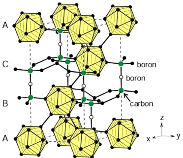
structures of the films with different silicon concentrations are illustrated in the insets. Modified from [23, 114]. ... 28 Figure 2.12 Crystal structure of B4C in hexagonal setting consisting of icosahedra formed by
boron atoms (solid circles) and linear C−B−C units. The ABC stackings of the rhombohedral structure are indicated at the left-hand side. Adapted from [134]. ... 30 Figure 2.13 (a) H of B4C films deposited by magnetron sputtering as a function of substrate
temperature, Ts; (b) Raman spectra of B4C films deposited at different Ts, and that of
boron carbide target material is shown for comparison. Adapted from [146]. ... 32 Figure 2.14 Band gap values of the B1−xCx films deposited by PECVD in dependence on the B/C
ratio. Adapted from [152]. ... 33 Figure 2.15 Hexagonal structure of TiB2 with a perspective view on the left and a projection
along the hexagonal axis on the right. Adapted from [134]. ... 34 Figure 2.16 (a) Compressive stress in the TiB2 films sputtered on Si (001) substrates as a function
of substrate bias, Us, at different Ts; (b) Microhardness of the TiB2 films sputtered on
WC substrates as a function of Us at different Ts. Adapted from [164]. ... 35
Figure 2.17 (a) XRD patterns from TiB2.4 film before and after annealing at different
temperatures, Ta; (b) H, lattice constant, c, and Γ0001 of the (0001) XRD reflection as a
function of Ta, and c of bulk TiB2 is indicated by an arrow for comparison; (c)
Bright-field XTEM image of TiB2.4 film after annealing at 700 °C. The corresponding SAED
pattern obtained near the upper portion is shown at the top right, and a higher-resolution image of the 0001-oriented ~5 nm wide subcolumnar nanostructure is shown at the lower right. Adapted from [159]. ... 36 Figure 2.18 (a) Band gap values of the BCN films deposited by PECVD at a Ts of 650 ºC as a
function of carbon content. The inset shows (αhν)1/2 plotted as a function of hν, adapted from [181]; (b) Band gap values of the BCN films deposited by RF magnetron sputtering at different Ts from 250 to 550 ºC. Adapted from [117]. ... 39
Figure 3.1 The working principle of magnetron sputtering. Electrons are restrained near the target surface by the Lorentz force in an inhomogeneous magnetic field, leading to an enhanced ionization of argon atoms. Adapted from [184]. ... 41 Figure 3.2 Formation of a dynamic equilibrium of zero net current and negative self-bias of
cathode with capacitive coupling at operation of deposition system in an RF mode: (a) Initial state; (b) Steady state. ... 42 Figure 3.3 Schematic of the magnetron sputtering deposition system (UPD 450, Teer Coatings
Ltd.) used to deposit the B1−xCxand Ti−B−C films in this work... 43
Figure 3.4 Schematic of the RF magnetron sputtering deposition system equipped with single target used for the BCN film deposition in this work. ... 44 Figure 3.5 Interaction volume of electrons and specimen atoms below a specimen surface, and
the escape volumes of different signals. Adapted from [186]. ... 46 Figure 3.6 Schematic diagram of photoelectron emission process induced by X-ray irradiation. 47 Figure 3.7 Elastic and inelastic scattering of incident light by molecules including Rayleigh,
Stokes, and anti-Stokes scattering. Modified from [187]. ... 49 Figure 3.8 Bragg diffraction by crystallographic planes. Modified from [186]. ... 50 Figure 3.9 Geometry of a Bragg–Brentano diffractometer. Adapted from [188]. ... 51 Figure 3.10 Depth-sensing indentation: (a) cross-section profile of sample surface at full load and
unload; (b) typical load-displacement curve. Adapted from [189]. ... 53 Figure 3.11 Two types of tribometers in different configurations: (a) pin-on-flat used in
reciprocating sliding tests; (b) pin-on-disk used in rotating sliding tests. ... 55 Figure 3.12 Schematic illustration of a three-electrode corrosion cell with a counter electrode
(CE), a working electrode (WE), and a reference electrode (RE). ... 56 Figure 3.13 Polarization curve of SS301 in 1 wt.% NaCl solution. ... 57 Figure 4.1 Carbon content in the B1−xCx films as a function of the power density applied to the
Figure 4.2 (a) Load-displacement curves for the B1−xCx films with the [C] contents of 19, 56, and
76 at.%; the inset presents a schematic representation of the load-displacement curve, where hr is the depth of the residual impression, hc is the contact depth, hmax is the
maximal penetration depth, Pmax is the maximum load, Wp is the plastic energy, and
We is the elastic energy; (b) Hardness, Young’s modulus, and elastic recovery of the
B1−xCx films as a function of the carbon content. ... 64
Figure 4.3 (a) Friction coefficient, μ, of the B1−xCx films with different carbon contents as a
function of the sliding distance measured by a rotating pin-on-disk tribometer. The inset shows the data measured by a linear reciprocating tribometers; (b) Wear rate, K, and friction coefficient, μ, of the B1−xCx films with different carbon contents. ... 66
Figure 4.4 Potentiodynamic polarization curves of B1−xCx films with different carbon contents. 68
Figure 4.5 XRD spectra of the B1−xCx films with different carbon contents. ... 69
Figure 4.6 Raman spectra of the B1−xCx films with different carbon contents. ... 70
Figure 4.7 B1s and C1s core level spectra of the boron-rich B0.81C0.19 and the carbon-rich
B0.24C0.76 films; experimental data (open circles), fitted results (solid lines) and their
deconvoluted components (dashed lines). ... 71 Figure 5.1 Variation of the film composition as a function of the power density applied to the
TiB2target: open symbols−XPS results; full symbols−RBS results. ... 80
Figure 5.2 Microstructural characteristics of the Ti−B−C films: (a) XRD spectra of films with different titanium contents; (b) effect of Ti content on the crystallite size determined from XRD measurements; and (c) SEM cross-section images of representative Ti−B−C films (Samples 1, 4, and 7) and of the TiB2 film. ... 82
Figure 5.3 Ti2p, B1s, and C1s core level XPS spectra of representative Ti−B−C films (Samples 1, 4, and 8). ... 84 Figure 5.4 (a) Load-displacement curves for Samples 1, 4, and 8 selected from the concentration
regions A, B, and C, respectively; (b) hardness and elastic modulus of the Ti−B−C films before and after annealing at 600 ºC as a function of titanium content. ... 86
Figure 5.5 (a) Variation of the friction coefficient of the Ti−B−C films with different titanium contents as a function of sliding distance. (b) Friction coefficients and wear rates of the Ti−B−C films with different titanium contents. Counter body: alumina ball; load: 2N. ... 89 Figure 5.6 Optical microscope images of the worn ball (a) and of the wear track (b) for Sample 1
after the pin-on-disk test; (c) SEM images of the wear track on Sample 1; (d) EDS spectra of the wear track and of the debris on Sample 1. ... 90 Figure 5.7 Optical microscope images of the worn ball (a) and of the wear track (b) for Sample 8
after the pin-on-disk test; (c) SEM images of the wear track on Sample 8; (d) EDS spectra of the wear track and the debris on Sample 8. ... 91 Figure 5.8 Potentiodynamic polarization curves of the Ti−B−C films with different titanium
contents. ... 92 Figure 5.9 Mechanical and tribological properties for the most frequently studied hard protective
coatings including our work on B-containing films: (a) hardness and (b) friction coefficient. ... 93 Figure 6.1 Representative FTIR spectrum collected from a pristine BCN film. ... 99 Figure 6.2 High resolution XPS spectra obtained from a pristine BCN film: (a) B1s, (b) N1s, and
(c) C1s core level spectra. The open circles are the raw data; the solid lines are backgrounds and fitted curves, while the dash lines are deconvoluted peaks corresponding to different chemical states. ... 100 Figure 6.3 UV-Vis absorption spectrum of a typical BCN film. The inset shows (αhν)1/2 plotted as
a function of photon energy. ... 102 Figure 6.4 (a) SEM image of ZnO NRs in a cross sectional view; (b) I-V characteristics of a
BCN/ZnO NRs heterojunction. Inset shows the I-V characteristics of ZnO/Al and BCN/Ag ohmic contacts and the schematic configuration of the heterojunction. .... 103 Figure 7.1 Tribo-mechanical properties for the most frequently studied hard protective coatings
including our work on B-containing films: (a) hardness; (b) Young’s modulus; (c) friction coefficient; (d) “Tribo-mechanical” map in terms of the hardness and friction coefficient. ... 107
LIST OF ACRONYMS AND SYMBOLS
Abbreviations:
a-C Amorphous carbon
a-C:H Hydrogenated diamond-like carbon
AlMgB14 Aluminum magnesium boron
a-Si3N4 Amorphous silicon nitride
B1−xCx Boron carbide
B2O3 Boron oxide
BCN Boron carbon nitride
BE Binding energy
Boron-containing B-containing
c-BN Cubic boron nitride
c-BCN Cubic boron carbon nitride
CE Counter electrode
CNx Carbon nitride
COSDAF Centre of Super-Diamond and Advanced Films
CVD Chemical vapor deposition
DC Direct current
DLC Diamond-like carbon
EDS Energy dispersive X-ray spectrometry
FCSEL Functional Coating and Surface Engineering Laboratory FESEM Field emission scanning electron microscope
FTIR Fourier transform infrared spectroscopy
FWHM Full width at half maximum
GDP Gross domestic product
H3BO3 boron acid
h-BCN Hexagonal boron carbon nitride
h-BN Hexagonal boron nitride
HDI Head-disk interfacial
HVOF High velocity oxy-fuel
KE Kinetic energy
NACE National Association of Corrosion Engineers nc-TiN Nanocrystalline titanium nitride
OCP Open circuit potential
PECVD Plasma enhanced chemical vapor deposition
PLD Pulsed laser deposition
PVD Physical vapor deposition
RBS Rutherford backscattering spectroscopy
RE Reference electrode
RF Radio frequency
RH Relative humidity
RT Room temperature
SCE Standard calomel electrode
SEM Scanning electron microscopy
SZM Structure zone model
ta-C Tetragonal carbon
TiB2 Titanium diboride
TM Transition metal
TiNx Titanium nitride
UHV Ultrahigh vacuum
WE Working electrode
XANES X-ray absorption near-edge spectroscopy
XPS X-ray photoelectron spectroscopy
XRD X-ray diffraction
ZnO Zinc oxide
Symbols
a Lattice constant
A Projected contact area
at.% Atomic percent
B Fitting constant in Oliver and Pharr model
c Lattice constant
ccrack Length of radial crack
d Interplanar spacing
dg Grain size
E Young’s modulus
E* Normalized delivered energy flux
EBD Breakdown potential
Ei Elastic modulus of indenter
Er Reduced modulus
Es Elastic modulus of sample
F Frictional force
H Hardness
h Planck’s constant
hdepth Indentation depth
hmax Maximal penetration depth
hr Depth of residual impression
I Current
I0 Saturation current
icorr Corrosion current density
Ii XPS peak intensity
JAr+ Incident Ar ion flux
JTi Ti flux
K Wear rate
k Boltzmann constant
k1 Hall-Petch material constant
m Fitting constant in Oliver and Pharr model
n Ideality factor
n1 Integer
P Applied load
Pmax Maximum indentation load
q Electronic charge
r Contacting sphere radius
R Elastic recovery
s Sliding distance
S Stiffness
Si Sensitivity factor
T Absolute temperature
T* generalized substrate temperature
Ta Annealing temperature
Tm Melting point
Ts Subsrate temperature
Us Substrate bias
V Voltage
Vloss Volume loss
Vt Thermal voltage
We Energy due to elastic deformation
Wp Energy due to plastic deformation
wt.% Weight percent
Greek symbols
α Absorption coefficient
α1 Empirical constant related to the indenter geometry
Γ Full width at half maximum intensity
Δυ Frequency difference
ε Strain
θ Diffraction angle
λ X-ray wavelength
λperiod Superlattice period
μ Friction coefficient
µ Mean friction coefficient
ν Frequency of the photon
νi Poisson’s ratio of indenter
νs Poisson’s ratio of sample
νvib Vibrational frequency of a molecule
σ Stress
σ0 Intrinsic yield stress
σprop Proportionality limit
σy Yield strength
υ Vibrational quantum number
CHAPTER 1
INTRODUCTION
1.1 Hard protective coatings
Hard protective coatings are generally applied on the surfaces of bulk materials with the intention of protecting them from damage or failure. The development of hard protective coatings is increasingly stimulated by the demands for enhanced surface tribo-mechanical properties of parts and components in various fields of application such as automotive, aerospace, microelectronics, and numerous others. More than $1 trillion USD (6.1% of the GDP) were lost as a result of corrosion in the USA in 2013 according to the report from NACE (National Association of Corrosion Engineers) [1]. In addition, one-third of the fuel energy is used to overcome the friction in engines, transmissions, tires, and brakes in passenger cars. For instance, around 360 million tons of oil was consumed globally in relation to friction in passenger cars in 2009 [2]. Such losses can be significantly reduced by applying hard protective coatings with improved tribo-mechanical and corrosion properties [3-7].
Chemical vapor deposition (CVD) and physical vapor deposition (PVD) are two important techniques extensively employed for hard protective coating fabrications [8-11]. The non-equilibrium nature of the deposition processes makes it possible to change the film properties by tuning the composition and the microstructure. Historically, the first CVD processes were developed for applications such as cutting tools [12]. This was followed by PVD; nowadays, arc deposition and magnetron sputtering are widely used techniques for hard coating fabrication owing to the relative ease of compositional and structural control, low substrate temperature without harmful gases, and generally good film adhesion.
A typical structure of hard protective coatings is schematically shown in Figure 1.1 (a). In general, substrate surfaces are processed with appropriate treatments before deposition to remove surface contamination and to enhance substrate hardness in order to match the mechanical properties of the subsequently applied coatings. Commonly, an adhesion enhancement layer is used between the substrate and the coating. For example, duplex treatment is commonly used to improve interfacial adhesion. This process consists of two independent steps: surface treatment leading to surface hardening, usually accomplished by nitriding or carburizing, followed by the deposition of a protective layer, often including an adhesion layer [10]. The main coating can
possess different architectures or nanostructures as illustrated in Figure 1.1 (b). With appropriate design, the coating performance can be enhanced with respect to the tribo-mechanical, corrosion, and other properties to meet specific requirements (see Figure 1.2).
Figure 1.1 (a) Typical structure of hard protective coatings; (b) different architectures or nanostructures of coatings illustrated by the schematics and the corresponding microscope images. Hard protective coatings with high wear resistance and high thermal stability have been extensively used on cutting tools for component machining. Application of such coatings, typically 3−5 μm thick, can enhance the durability of the tool, the machining speed, as well as the quality of the cutting process. Coatings of transition metal carbides and nitrides, such as TiC and TiN, are widely employed.
Components with strengthened and lubricious surfaces are required in the automotive industry. The very high energy consumption caused by friction can be reduced by applying coatings with low friction. In addition, the lifetime of components can be improved significantly by using hard and wear resistant coatings [2, 13]. For instance, diamond-like carbon (DLC) coatings have been successfully applied on different automotive parts such as piston rings to reduce friction, and hence to lower fuel consumption and enhance the overall efficiency [14, 15].
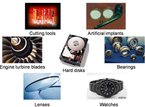
Figure 1.2 Examples of the applications of multi-functional protective coatings.
Protective coatings with multi-functional characteristics (see Figure 1.3) combining film properties, such as selective optical absorption, color, or electrical conductivity with the mechanical, tribological, and corrosion protection, open new applications in other areas including optics, microelectronics, biomedical, magnetic storage media, and consumer products as shown in Figure 1.2. Of particular interests are the following applications.
(i) Optics. Tribo-mechanical properties of the optical coatings on the components such as lenses or glass screens need to meet the minimum requirements to prevent damage such as scratches. In addition, optical coatings with very low permeability of moisture is also very important as the absorption of water vapor can significantly affect the optical characteristics and induce stress which may cause coating delamination and long term instability [16].
(ii) Biomedical applications. The protective coatings for biomedical devices such as artificial implants are required to possess low friction and high wear resistance. In addition, the coatings need to be biocompatible and withstand the effect of highly corrosive environments including body cells and fluids. DLC coatings meeting these requirements have been used to in such applications [17].
(iii) Magnetic storage media. Hard disks are usually coated with protective layers which can decrease the friction and wear of occasional head-disk contacts and the corrosion of the head and
of the magnetic media [18]. With the requirement of increasing the storage density, the thickness of the protective layers is limited by the head-disk interfacial (HDI) spacing. Therefore, smooth and dense coatings with enhanced tribo-mechanical and corrosion properties and high thermal stability such as DLC [19, 20] and carbon nitride (CNx) [21, 22] are widely used in hard disks.
Figure 1.3 Schematic illustration of a functional coating system, modified from [23].
1.2 Motivation of the present work
It is very important to control the coating properties by the design of coating architecture and microstructure as illustrated in Figure 1.1 (b). Single layer coatings with homogeneous composition can provide primary protection of the substrate. However, the coating performance such as adhesion and strength can be further improved by applying different microstructures. For example, gradient coatings with gradual transitions of the coating properties across the thickness and without sharp interfaces exhibit adhesion superior to that of single layer coatings [24]. Moreover, strengthening of conventional materials following the Hall-Petch relationship [25] is limited when the grain size is close to 10 nm and below. This limitation can be overcome by developing nanostructured materials including superlattices and nanocomposites. Superlattice films consist of two different alternating layers with a period typically of 5−10 nm, whereas nanocomposite coatings are composed of nanocrystallites embedded in an amorphous or a nanocrystalline matrix. Both of these systems exhibit superior mechanical performance compared to single phase materials. This is generally explained by the increase of interface density. For superlattice films, sharp interfaces between alternating layers with different elastic moduli can
hinder dislocation movements and consequently enhance the mechanical properties. For nanocomposites, the strong interfaces between the different crystalline phases can prevent grain boundary sliding and hence achieve strengthening. However, it is still a challenge to determine more precise rules to control the film structure and properties. The main reason tends to be that the coating properties are determined by the structures at different scales, including the bonding states and the microstructure which are rather complex, and are affected by the many factors.
The development of new and novel protective coatings with high hardness, high wear resistance, and additional functions are strongly stimulated by the industrial demands such as extension of the part lifetime, energy-saving, cost reduction, and performance enhancement. Numerous materials, such as diamond, transition metal nitrides and carbides, and DLC have been used as protective coatings in different fields, but there are still numerous problems to be solved. For example, poor adhesion and high deposition temperature of diamond coatings restrict their application despite their high hardness of ~100 GPa. c-BN coatings with a hardness of 50−70 GPa are good candidates for hard protective coatings, but the high built-in compressive stress limits the applicable coating thickness and gives rise to poor adhesion. TiN is widely used as hard and wear resistant coating for cutting tools; however, the low oxidation resistance (< 500 ºC) restricts its high temperature applications. DLC films are very popular for automotive tribo-components and biomedical devices due to their relatively high hardness and elasticity, low friction, and low wear rate. However, their applications are limited by the low thermal stability (< 300 ºC) and frequently poor adhesion caused by high compressive stress.
1.3 Objectives
Boron-containing (B-containing) materials such as boron carbide (B1−xCx) and titanium
diboride (TiB2) are very attractive, due to their excellent mechanical properties. For example,
B4C with a hardness of ~40 GPa is the third hardest traditional bulk material at room temperature
after diamond and c-BN. Its high thermal stability, up to 1700 K, makes it a good candidate for tribo-mechanical applications at high temperature. Its low mass density of 2.52 g/cm3, low thermal expansion coefficient of 4.3×10⁻⁶ K−1, high chemical stability, and good wear resistance make B4C a suitable candidate for different industrial applications. For comparison, TiB2 is a
ceramic compound well known for its high hardness of ~30 GPa, high thermal conductivity of 96 W/mK, and chemical inertness. Moreover, the electronic characteristics of B-containing materials
are very interesting as well. Boron carbon nitride (BCN) exhibits adjustable optical and electrical properties due to its structural similarity to carbon (graphite and diamond) and boron nitride (BN in hexagonal and cubic phases). Therefore, the present thesis is primarily motivated by the prospects of the performance of B-containing materials in the form of thin films and coatings with the goal of providing attractive properties as hard protective coatings and multi-functionality, for example with their electrical and optoelectronics characteristics.
In relation to the above, the main objectives of this thesis can be formulated as follows: to develop hard B-containing nanocomposite protective coatings using magnetron sputtering, to enhance the coating performance by controlling the microstructure on the nanoscale including nanocomposite, nanocolumn, nanorod, and multilayer features, to study the effect of composition and microstructure on their tribo-mechanical and corrosion behaviors, and to explore their potential for new applications due to their multi-functional characteristics.
Specific objectives can be summarized as follows:
To tailor the tribo-mechanical properties of boron carbide films via the B1−xCx composition;
To study the structural evolution and the tribo-mechanical properties by doping B1−xCx with
Ti to obtain Ti−B−C nanocomposite films;
To develop high quality BCN/ZnO-nanorods p-n heterojunctions based on magnetron sputtered BCN films.
1.4 Organization of the thesis
The thesis is composed of seven chapters. The research subject is introduced in the present Chapter 1. Chapter 2 offers background knowledge on the development of hard protective coatings and a review of the characteristics of B-containing films. The methodologies related to the deposition and characterization techniques in this work are described in Chapter 3. The principal results with respect to the tribo-mechanical and electrical properties of the B-containing coatings are presented in the form of three peer-reviewed articles in Chapters 4, 5, and 6 in the following logical sequence of thought: First, the tribo-mechanical properties of B1−xCx films are
tailored by controlling the carbon content (Article 1, Chapter 4). Based on the optimized B1−xCx
composition, Ti is added into the B1−xCx system to form Ti−B−C nanocomposite in order to
Chapter 5). Finally, BCN films are obtained by introducing nitrogen into the B1−xCx system
(Article 3, Chapter 6). Their optical and electrical properties are studied with the purpose of exploring new applications of the B-containing films.
Chapter 4 (Article 1) describes the microstructure and tribo-mechanical properties of the B1−xCx films deposited by magnetron sputtering. The tribo-mechanical behaviors of the B1−xCx
films are tailored by adjusting the carbon content, and the corresponding hardening and tribological mechanisms are discussed.
Chapter 5 (Article 2) presents the effect of adding the third element, Ti, to form Ti−B−C nanocomposite films. The mechanical properties of the Ti−B−C nanocomposites are controlled by the titanium content and the microstructural features, while their tribological properties are closely related to the surface chemical states and the mechanical properties.
Chapter 6 (Article 3) reports the optical and electrical characteristics of sputtered BCN films as well as their application in electronic devices. ZnO nanorods were grown over the BCN films to form BCN/ZnO nanorods p-n heterojunctions, the performance of which is assessed by the rectification ratio determined from the I-V characteristics.
Finally, Chapter 7 offers a general discussion and the main conclusions of the work accomplished throughout the thesis. Future perspectives and promising directions are proposed as well.
This thesis work gave rise to numerous publications. Specifically, Table 1.1 lists the three publications representing the heart of this thesis as well as other publications accomplished in collaboration with others. The results of this work were also presented in oral and poster forms at various international conferences and symposia as summarized in Table 1.2.
Table 1.1 Publications resulting from this Ph.D. project and collaborations Papers in peer-reviewed journals
J. C. Qian, Z. F. Zhou, C. Yan, D. J. Li, K. Y. Li, S. Descartes, R. Chromik, W. J.
Zhang, I. Bello, L. Martinu, and J. E. Klemberg-Sapieha, “Tailoring the mechanical and tribological properties of sputtered boron carbide films via the B1−xCx composition”, Surface
& Coatings Technology, 267 (2015) 2 (Article 1).
J. C. Qian, Z. F. Zhou, K. Y. Li, W. J. Zhang, I. Bello, L. Martinu, and J. E.
Klemberg-Sapieha, “Microstructure and tribo-mechanical properties of Ti−B−C nanocomposite films prepared by magnetron sputtering”, Surface & Coatings Technology, 270 (2015) 290 (Article 2).
J. C. Qian, S. K. Jha, B. Wang, E. V. Jelenković, I. Bello, J.E. Klemberg-Sapieha, L.
Martinu, and W.J. Zhang, “High quality boron carbon nitride/ZnO-nanorods p-n heterojunctions based on magnetron sputtered boron carbon nitride films”, Applied Physics Letters, 105 (2014) 192104 (Article 3).
C. Yan, J. C. Qian, T. W. Ng, Z. F. Zhou, K. Y. Li, W. J. Zhang, I. Bello, L. Martinu, J. E. Klemberg-Sapieha, “Sputter deposition of hard quaternary Al−Mg−B−Ti nanocomposite films”, Surface & Coatings Technology, 232 (2013) 535.
C. Yan, S. K. Jha, J. C. Qian, Z. F. Zhou, B. He, T. W. Ng, K. Y. Li, W. J. Zhang, I. Bello, J. E. Klemberg-Sapieha, and L. Martinu, “Electronic structure and electrical transport in ternary Al−Mg−B films prepared by magnetron sputtering”, Applied Physics Letters, 102 (2013) 122110.
Z. H. Chen, S. Y. Yeung, H. Li, J. C. Qian, W. J. Zhang, Y. Y. Li, and I. Bello, “Controlled growth of ZnO/Zn1−xPbxSe core-shell nanowires and their interfacial electronic
energy alignment”, Nanoscale, 4 (2012) 3154.
S. Jha, J. C. Qian, O. Kutsay, J. K. Jr, C. Y. Luan, J. A. Zapien, W. J. Zhang, S. T. Lee, and I. Bello, “Violet-blue LEDs based on p-GaN/n-ZnO nanorods and their stability”, Nanotechnology, 22 (2011) 245202.
S. Descartes, J. C. Qian, R. Chromik, Z. F. Zhou, K. Y. Li, and J. E. Klemberg-Sapieha, “Effect of carbon content on the tribological properties of sputtered boron carbide (B1−xCx)
films”, in preparation.
Papers in conference proceedings
J. C. Qian, Z. F. Zhou, C. Yan, D. J. Li, K. Y. Li, S. Descartes, R. Chromik, W. J.
Zhang, I. Bello, L. Martinu, and J. E. Klemberg-Sapieha, “Tailoring the mechanical and tribological properties of sputtered boron carbide films via the B1−xCx composition”, 57th
Table 1.2 Oral and poster presentations at conferences and symposium Oral presentations
J. C. Qian, Z. F. Zhou, C. Yan, D. J. Li, K. Y. Li, S. Descartes, W.J. Zhang, I. Bello, L.
Martinu, J.E. Klemberg-Sapieha, “Tailoring the mechanical and tribological properties of boron carbide films by adjusting the BCx stoichiometry”, ICMCTF, May 2013. San Diego,
CA USA.
J. C. Qian, C. Yan, Z. F. Zhou, K. Y. Li, W. J. Zhang, I. Bello, L. Martinu, and J.E.
Klemberg-Sapieha, “Mechanical and tribological properties of B-containing hard protective nanocomposite coatings deposited by magnetron sputtering”, SVC Conference, May 2014. Chicago, IL USA.
Poster presentation
J.C. Qian, Z. F. Zhou, C. Yan, S. Descartes, K. Y. Li, W. J. Zhang, I. Bello, R.
Chromik, L. Martinu, and J. E. Klemberg-Sapieha, “Effect of structure evolution on tribo-mechanical properties of B-containing nanocomposite deposited by magnetron sputtering for hard protective coatings”, 7th Symposium on Functional Coatings and Surface Engineering (FCSE), Jun 2014. Montréal, QC Canada.
1.5 Statement of contributions
In this thesis, the main results are presented in a form of three articles that have a certain number of co-authors as dictated by the collaborative character of this thesis. Clearly, the candidate (Jincheng Qian) is the principal (first) author in all of them; her specific contributions to each of the articles are described below.
Chapter 4 (Article 1):
J. C. Qian participated in the definition of the project, experiment design, analysis of all the samples, plotting all the graphs, interpretation of results, and preparation of the manuscript. Z. F. Zhou assisted with the coating deposition. C. Yan helped in the XRD measurements (Figure 4.5). D. J. Li and S. Descartes assisted with the measurements of the tribological properties (Figure 4.3 (a)). K. Y. Li provided the magnetron sputtering deposition system. R. Chromik provided the pin-on-disk tribometer (reciprocating mode). W. J. Zhang, I. Bello, L. Martinu, and J. E. Klemberg-Sapieha supervised the project, they commented on the results interpretation and they helped to assure a good quality of English.
Chapter 5 (Article 2):
J. C. Qian participated in the definition of the project, experiment design, analysis of all the samples, plotting all the graphs, interpretation of results, and preparation of the manuscript. Z. F. Zhou assisted with the coating deposition. K. Y. Li provided the magnetron sputtering deposition system. W. J. Zhang, I. Bello, L. Martinu, and J. E. Klemberg-Sapieha supervised the project, and commented on the results interpretation and on the preparation of the article.
Chapter 6 (Article 3):
J. C. Qian participated in the definition of the project, experiment design, analysis of all the samples, plotting all the graphs, interpretation of the results, and preparation of the manuscript. S. K. Jha participated in the preparation and analysis of the p-n junction (Figure 6.4), and preparation of the manuscript. B. Wang participated in the preparation of the ZnO nanorods (Figure 6.4). E. V. Jelenković participated in the Hall measurements. I. Bello, J.E. Klemberg-Sapieha, L. Martinu, and W.J. Zhang supervised the project, and they commented on the analysis of the results and on the preparation of the article.
CHAPTER 2
LITERATURE REVIEW
This chapter reviews the background knowledge of this thesis work, based on theory and on literature reviews. The development of hard protective coatings including intrinsic and nanostructured hard coatings is introduced. The dependence of hardness upon the structure at different scales is illustrated by different coatings and coating systems, and the feasible approaches to hardness improvement are discussed. Finally, B-containing coatings are addressed with respect to their structural, tribo-mechanical, and electrical properties.
2.1 Hard protective coatings
2.1.1 Mechanical properties
The mechanical properties of a material refer to its elastic and plastic response when external forces are applied. They are generally characterized by the relationship between stress, σ, and strain, ε, as shown in Figure 2.1. The elastic response of the material is represented by the linear part of the σ-ε curve which can be described by Hooke’s law, with the elastic or Young’s modulus, E:
σ = Eε. (2.1) In this regime, the deformation of a material is reversible.
Figure 2.1 Schematic presentation of the stress-strain relation for brittle and ductile materials. Adapted from [26].
When the stress is higher than the proportionality limit, σprop, the material cannot fully
recover its original shape, and Hooke’s law is not applicable. Yield strength, σy, is defined as the
stress at which plastic deformation occurs, and it represents the strength of the material. However, it is difficult to determine σy of a surface or a thin film in practice. Instead, hardness, H and E are
measured using indentation tests, and accordingly other mechanical properties can be obtained from the H and E values. H is generally defined as the ratio of the applied load over the projected contact area, which is essentially the contact pressure as an indenter is pressed into a material surface. It represents the resistance of a solid material to both elastic and plastic deformations. The resistance of a coating to plastic deformation is proportional to H3/E2 since the yield pressure, Py, in a rigid-ball contact can be determined by the equation [27, 28],
3 2 y 0.78 ( 2) H P r E = , (2.2) where r is the contacting sphere radius.
Fracture toughness, KC, is another important factor for evaluating the mechanical properties
of hard materials. It indicates the resistance to crack propagation. KC can be obtained by
1/ 2 max C 1 3/ 2 crack (H) ( P ) K E c α = , (2.3)
where Pmax is the maximum indentation load, ccrack is the length of radial crack, and α1 is an
empirical constant related to the indenter geometry. Equation 2.3 indicates that every increase of the H/E ratio can improve the coating fracture toughness.
The hardness of a material is determined by its intrinsic hardness and by its microstructural characteristics [29]. Intrinsic hard materials are generally characterized by their high cohesive energy, short bond length, and a high degree of covalent bonding [30-32]. The dependence of hardness on the cohesive energy per molar volume, as illustrated in Figure 2.2, demonstrates that higher H values can be achieved with higher cohesive energy and shorter bond length. The deformation mechanisms of materials are also affected by their microstructural features, such as grain boundaries, dislocations, impurity atoms, and vacancies. In general, materials can be strengthened by increasing the defect density and reducing the grain size as a result of hindering dislocation movement. In consequence, the H values of thin films are often higher than those of corresponding bulk materials, due to the higher defect concentration and the smaller grain size in the films, particularly when they are deposited at low temperature with respect to their melting point [25, 29].
Figure 2.2 Relationship between hardness and cohesive energy per molar volume. Modified from [30].
The mechanical properties of materials are determined not only by the nature of their atomic bonds but also by their structure at different scales. Conventional metallic materials can be strengthened by plastic deformation because the growth of dislocation density during such process can increase the interaction between dislocations, and thus lead to a higher hardness [33]. Strengthening can also be achieved by increasing the grain boundary fraction, which can hinder the multiplication and movement of dislocations [25]. Therefore, hardening can be achieved by grain refinement, and such effect can be described by the Hall-Petch relationship [25],
y 0 1 g 1 k d σ =σ + , (2.4)
where σ0 is the intrinsic yield stress, dg is the grain size, and k1 is a constant. However, this
relationship is not valid when the crystallite size is lower than about 10 nm [34].
The microstructure of thin films can be controlled by the deposition conditions such as pressure, substrate temperature, and the energy of ion bombardment. The structure zone model (SZM) is used to describe the effect of deposition parameters on the thin film morphology and
microstructure. The latest SZM proposed by A. Anders [35] is illustrated in Figure 2.3. The film microstructure in three-dimensional space varies with two parameters, generalized substrate temperature, T*, and normalized delivered energy flux, E*. The microstructural evolution can be divided into four zones. In zone 1, the film has a high density of porous grain boundaries and defects due to the low adatom mobility and shadowing effects. In zone T, the film possesses a transition structure consisting of densely fibrous grains. Such densification is caused by the rising mobility at higher temperature and higher ion energy fluxes. In zone 2, the film exhibits a columnar structure, and the grain size increases with the temperature. In zone 3, the high energy enables bulk diffusion and recrystallization, which leads to the increase of the grain size.
Figure 2.3 Structure zone diagram applicable to energetic deposition. Adapted from [35].
The SZM demonstrates that the film microstructure can be adjusted by the substrate temperature and ion bombardment. Hard protective coatings are usually deposited at low temperatures, which are generally less than 0.2−0.3 of the melting point, Tm, in K [36]. Therefore,
ion bombardment is commonly used to modify the film microstructure during plasma-assisted growth. In general, defects created by the energetic particle bombardment can induce stress which has a close relation with the mechanical properties of the films. For magnetron sputtering
deposition, the energetic particles are commonly generated from sputtering gas and accelerated towards the growing films by a negative substrate bias [25, 37], and the intrinsic stress typically increases with the square root of the bombarding particle energy [25, 38].
According to their hardness, coatings can be divided into three groups: (i) Hard coatings with H > 20 GPa; (ii) Superhard coatings with H > 40 GPa; and (iii) Ultrahard coatings with H > 70 GPa [27]. The mechanical properties for the most frequently studied hard coatings are compared in Figure 2.4. Further in this chapter, these coatings are reviewed in detail with respect to their deposition process, structural characteristics, and tribo-mechanical properties.
Figure 2.4 Mechanical properties for the most frequently studied hard coatings: (a) hardness, modified from [23]; (b) Young’s modulus.
2.1.2 Tribology
The tribological properties, namely the friction coefficient, μ, and the wear rate, K, are also very important factors for the evaluation of the performance of hard protective coatings. Friction coefficient is defined as the ratio of the frictional force, F, over the normal applied force, P,
F P
µ = . (2.5) The wear rate is described as the volume loss, Vloss, divided by P and the sliding distance, s,
loss V K P s = × . (2.6)
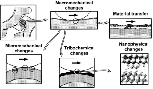
The tribological process involving two contacting surfaces in relative motion is very complex because both physical and chemical changes take place and lead to different friction-, wear-, and deformation mechanisms at different scales. Therefore, it is necessary to analyze the tribological changes including the mechanical changes on both macro- and micro- scales as well, the chemical effects, and the material transfer at the interfaces as illustrated in Figure 2.5 [39].
Figure 2.5 Different tribological changes that can affect the tribological contact mechanisms. Adapted from [39].
The macromechanical mechanisms relate the tribological properties to the σ-ε distribution in the contact area, the elastic-plastic deformations, and the formation of wear particles (debris, tribofilms) and its dynamics. Four main parameters are used to analyze the tribological contact behavior [39]: (i) the coating-to-substrate hardness relationship; (ii) the film thickness; (iii) the surface roughness; and (iv) the debris in the contact. When a hard spherical surface slides on a coating, twelve typical contact conditions featured by specific tribological contact mechanisms with respect to the above four parameters have to be taken into account as schematically shown in Figure 2.6.
Figure 2.6 Macromechanical contact conditions for different mechanisms which influence friction when a hard spherical slider moves on a coated flat surface. Adapted from [39].
In the present work, we focus on the contact conditions of hard coatings on softer substrates. The hard coatings can decrease friction and wear by preventing ploughing, and the residual compressive stresses often existing in the coatings. Increase of the substrate hardness can reduce the friction and wear as the load support is improved, and thus deflections and ploughing are inhibited. Thick hard coatings can also increase load carrying capacity of soft substrates. Rough surfaces may reduce the real contact area, although the asperities may participate in abrasive or fatigue wear. Particles or debris are commonly formed during the tribological process. Their effect on friction and wear depends upon the particle size, the coating thickness, the surface roughness, and the hardness relationship of the particle, coating, and substrate. Under certain circumstance, tribo-chemical effects have also to be taken into account. The friction for the most frequently studied hard coatings corresponding to Figure 2.4 are shown in Figure 2.7.
Figure 2.7 Friction coefficient for the most frequently studied hard coatings.
2.1.3 Diamond and c-BN films
Diamond and c-BN with very similar structure are described as ultrahard materials. Their attractive mechanical, thermal, optical, and electronic properties make them suitable for numerous applications including hard protective coatings.
Diamond films
Diamond is well known as the hardest naturally occurring material as shown in Figure 2.2. It is made up of carbon atoms with a variation of the face-centered cubic crystal structure called a diamond lattice. The fourfold covalent bonds with small size of atoms are strong and short, which leads to the highest atomic density (1.17×1017 cm−3) and extremely high H values, ranging from about 80 to 100 GPa [40]. The tribological properties of diamond are also very attractive as indicated by their low friction coefficient in humid air or dry nitrogen and high wear resistance due to its high hardness and elasticity [41]. However, the applications of diamond such as cutting tools are limited by its high deposition temperature and the high solubility of carbon in iron and in many other metals.
In the 1950s, diamond was first synthesized by high pressure and high temperature (HPHT) methods, which simulate the conditions for natural diamond growth [42, 43]. The development of CVD techniques made it feasible to deposit diamond films in nanocrystalline and polycrystalline forms on substrates which can endure CVD environment and temperature [44-46]. The typical deposition temperature of diamond films is in the range of 1000 to 1400 K [47]. Generally, pretreatments, such as polishing the substrate surfaces with diamond powder and bias enhanced nucleation with a carbon source, are used to increase the nucleation density [41].
c-BN films
Single crystal c-BN with an H value of ~75 GPa is synthetic, and is the second known hardest material [48]. c-BN exhibits a structure similar to that of diamond, and its atomic density is smaller by only 4.3% than that of diamond. Consequently, the high atomic density and strong chemical bonds lead to the superhard feature of c-BN. In addition, the thermal stability and chemical inertness of c-BN even surpass that of diamond. For example, c-BN is chemically inert against molten ferrous materials [49] and very stable to oxidation at high temperature [50]. Nevertheless, c-BN coatings have not been used in practice so far, mainly due to the poor adhesion induced by the high compressive stress in the coatings.
The severe conditions of the HPHT methods and the size limitation of the c-BN grains promote the synthesis of c-BN thin films by ion-assisted PVD or CVD techniques [46, 51-53]. The H values of c-BN thin films are typically in the range of 50–70 GPa. As in the bias enhanced nucleation for diamond film deposition, ion bombardment with an energy ranging from 50 to 1000 eV is essential for the nucleation and growth of c-BN films. However, a high compressive stress of 5−20 GPa is inevitably induced. In consequence, delamination of c-BN films usually takes place when the film thickness is greater than 200 nm due to the high internal stress. Considerable effort has been devoted to overcoming the thickness limitation, including reduction of the ion energy [54, 55], increase of the substrate temperature [54, 56], post-deposition treatment [57], a two-step process with reduced bias [54], and utilization of buffer or gradient layers [48, 52, 58]. Using one or a combination of these methods, thicknesses of ~2 μm can be achieved for c-BN films on certain substrates such as silicon and tungsten carbide [59].
2.1.4 DLC and CN
xfilms
DLC films
DLC is a metastable form of amorphous carbon, which contains a significant fraction of sp3 type carbon bonds. It exhibits the high hardness, low friction coefficient, low wear rate, and chemical inertness. DLC films can be classified into two major groups, namely hydrogenated and hydrogen-free DLC films. Generally, the hydrogenated DLC (a-C:H) films are characterized by a hydrogen content in the range of 10−50 at.% [7, 60-63] and an sp3
bond fraction smaller than 50%; hydrogen-free tetragonal carbon (ta-C) films are characterized by a small amount of hydrogen and a high sp3 bond fraction of more than 85% [63]. The structure and properties of DLC films are determined by the hydrogen concentration and the sp3/sp2 ratio of the carbon bonds [64]. A simulated atomic structure of a typical a-C:H film is shown in Figure 2.8. It can be described as a network of carbon atoms bonded in sp2 and sp3 hybridization, with some bonds terminated by hydrogen [65, 66].
Figure 2.8 A simulated atomic structure of a typical a-C:H film. Adapted from [66].
The mechanical properties of DLC films are directly related to the fraction of sp3 bonds. Specifically, the hardness and the internal stress increase with higher sp3/sp2 ratio [67, 68]. Typical H values for DLC films are between 10 and 30 GPa [63, 69], and the internal stress varies in the range of 0.5−7 GPa [63]. N, Si, O, or metals [70] may be incorporated in the DLC

![Figure 2.2 Relationship between hardness and cohesive energy per molar volume. Modified from [30]](https://thumb-eu.123doks.com/thumbv2/123doknet/2344959.34666/39.918.298.626.119.525/figure-relationship-hardness-cohesive-energy-molar-volume-modified.webp)
![Figure 2.3 Structure zone diagram applicable to energetic deposition. Adapted from [35]](https://thumb-eu.123doks.com/thumbv2/123doknet/2344959.34666/40.918.155.771.409.812/figure-structure-zone-diagram-applicable-energetic-deposition-adapted.webp)
![Figure 2.4 Mechanical properties for the most frequently studied hard coatings: (a) hardness, modified from [23]; (b) Young’s modulus](https://thumb-eu.123doks.com/thumbv2/123doknet/2344959.34666/41.918.126.798.387.681/figure-mechanical-properties-frequently-studied-coatings-hardness-modified.webp)