HAL Id: hal-00369082
https://hal.archives-ouvertes.fr/hal-00369082
Submitted on 18 Mar 2009
HAL is a multi-disciplinary open access
archive for the deposit and dissemination of
sci-entific research documents, whether they are
pub-lished or not. The documents may come from
teaching and research institutions in France or
abroad, or from public or private research centers.
L’archive ouverte pluridisciplinaire HAL, est
destinée au dépôt et à la diffusion de documents
scientifiques de niveau recherche, publiés ou non,
émanant des établissements d’enseignement et de
recherche français ou étrangers, des laboratoires
publics ou privés.
SatIPSec : an optimized solution for securing multicast
and unicast satellite transmissions
Laurence Duquerroy, Sébastien Josset, Olivier Alphand, Pascal Berthou,
Thierry Gayraud
To cite this version:
Laurence Duquerroy, Sébastien Josset, Olivier Alphand, Pascal Berthou, Thierry Gayraud. SatIPSec :
an optimized solution for securing multicast and unicast satellite transmissions. 22nd AIAA
Inter-national Communications Satellite Systems Conference, May 2004, Monterey, United States. 11p.
�hal-00369082�
SatIPSec : an optimized solution for securing multicast and
unicast satellite transmissions
L.Duquerroy* and S. Josset† Alcatel Space, Toulouse, France O. Alphand‡, P. Berthou§ and T. Gayraud¥
LAAS-CNRS, 7 av. du Colonel Roche, 31077 Toulouse Cedex 04, France
In satellite networks, the security of data exchanged on the satellite segment is threatened by many types of attacks such as eavesdropping, intrusion of unauthorized satellite terminals, satellite terminal cloning… The integration of security mechanisms is therefore considered today as an essential requirement. Some existing solutions may be recommended, however they do not offer all the necessary security services. For instance, the optional security mechanisms defined in the DVB-RCS standard provide insufficient security support, especially in satellite networks with natural broadcast/multicast capability over large areas. The use of well-known upper layers security protocols such as SSL (Secure Socket Layer) or IPSec/IKE can be considered too, but they are dedicated to unicast communications. The SatIPSec solution has been designed to provide an optimized and adapted security solution for satellite networks. It offers a new way of transparently and efficiently securing unicast and multicast satellite transmissions, with a strong access control, data confidentiality, data integrity, and data authentication as security services. SatIPSec has recently been implemented in a demonstrator developed in the context of the SATIP6 IST project. In this implementation, which allows to manage centrally secure multicast groups and Virtual Private Networks, key distribution is achieved according to the “Flat Multicast Key Exchange” protocol of SatIPSec, and data are encrypted and authenticated according to the IPSec protocol adapted to multicast. This paper introduces the principles of the security mechanisms involved in SatIPSec, and presents the features of the implementation and its results.
Nomenclature
AH = Authentication Payload ESP = Encapsulating Security Payload FMKE = Flat Multicast Key Exchange GCKS = Group Controller Key Server GDOI = Group Domain of Interpretation IKE = Internet Key Exchange
IPSec = IP Security
SA = Security Association ST = Satellite Terminal VPN = Virtual Private Network
* Advanced Telecom Satellite Systems, Research Department, Alcatel Space, [email protected] † Advanced Telecom Satellite Systems, Research Department, Alcatel Space, [email protected] ‡
LAAS-CNRS , [email protected]
§
Associate Professor (Toulouse University of Science), LAAS-CNRS, [email protected]
I.
Introduction
The security of data exchanged in networks is today a major concern for all network designers. Many security solutions have been developed, and current satellite systems enable security solutions dedicated to satellite context. However, most of them come from the “Broadcast” world and therefore focus on basic security services that a one-way broadcasting system requires. With the evolution towards two-one-way satellite systems (DVB-RCS) that support various types of connectivity (in particular multicast links), new security requirements appear (confidentiality and integrity on forward and return links, for multicast and unicast transmissions, authentication of satellite terminals…) that existing security solutions for satellite-based networks cannot satisfy. Besides the DVB-RCS standard defines optional security mechanisms, but they provide insufficient security support, especially in satellite networks with natural broadcast/multicast capability. The use of well-known uppers layers security protocols defined initially for terrestrial networks may be suggested, but they are dedicated to unicast communications. One example is the IPSec standard, which is the most widely used security protocol in terrestrial networks, and which offers strong security services. It could be implemented in multicast environment. However it would not provide an optimized solution because of its key exchange protocol (called Internet Key Exchange – IKE 1), which is dedicated to point-to-point communications. Indeed, in order to protect a multicast flow between a sender and several recipients, an IPSec tunnel should be established between the sender and each recipient. The sender should then duplicate each multicast packet, encrypt independently the copies and encapsulate them in their respective IPSec tunnel. This solution does not therefore take advantage of the natural broadcast capability of the satellite link.
This paper introduces a new security solution called SatIPSec 2,3, which has been designed to satisfy the new data security requirements of satellite systems. This solution, dedicated to satellite-based networks, offers a new way of transparently and efficiently securing unicast and multicast satellite transmissions. It avoids in particular multicast packet duplication and multiple encryption computations per packet. SatIPSec has recently been implemented in a demonstrator developed in the context of the IST SATIP6 project. This implementation, where the key distribution is achieved according to the Flat Multicast Key Exchange protocol (FMKE)4 of SatIPSec, and where unicast and multicast data are encrypted and authenticated according to the IPSec ESP protocol 5, is presented in the following. Besides, this implementation works in IPv4 and IPv6.
II.
SATIP6
6architecture overview
A. Presentation of SATIP6
The objective of SATIP6 project is to evaluate and demonstrate key issues of the integration of satellite-based access networks into the Internet in order to offer multimedia services over wide areas. IP serves as the common denominator to allow interoperability for services and transport technology within integrated networks. Most immediate technical issues facing satellite broadband access in the coming years are examined, namely the functions to be implemented in the protocol layer between physical medium access and the IP Layer (i.e. typically layer 2). The project is considering two stages:
• short-to-medium term, focussing on better adaptation of DVB-RCS access for IP services with current satellites,
• longer term, in which protocols more optimized for IPv6 are introduced, and considering next generation satellites (including both transparent and regenerative payloads).
This paper is related to the second step. In this step, the shorter term solutions defined for IP/DVB-RCS have been extended and adapted for more advanced satellite systems supplemented with mesh connectivity (directly between users) via transparent or regenerative payloads (with on-board packet switching). In addition, satellite integration into Next Generation Networks (NGN), based on IPv6 and associated with a range of advanced features (in terms of mobility and security for instance), has been targeted. Moreover Layer 2 protocols, such as “IP-dedicated” 7 introduced in the IST BRAHMS 8 project, has been further defined for more optimized transport of IPv6 over satellite (compared with MPLS).
The introduction of IPv6 into the Internet is seen as the paving the way to the next leap forward in telecoms services, and opening up a wide range of new and enhanced service capabilities. Besides, the introduction of satellite-based IPv6 transport through systems with wide coverage areas should allow users in many regions, where IPv6 services are non-existent or slow to be introduced, to gain early and high speed access to advanced services. Many satellite digital TV services have been introduced in recent years, and Internet services are being introduced on the back of them, using DVB standards. More recently return channels via satellite based on DVB-RCS have also been considered, which seems to offer the most immediate market opportunity for IP services.
The introduction of IPv6 (compared to today's IPv4) requires modification of user applications and network infrastructure. This is a gradual process, which has to be implemented differently in different parts of the global network. The satellite system and notably the satellite transport protocols, as well as the interfacing and inter-working with the core network at the gateway stations, have to be adapted to provide cost-effective services compatible with terrestrial network IPv6 services. The SATIP6 project has tackled these different issues.
B. Overview of the emulated satellite system architecture.
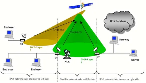
One of the starting points of the SATIP6 project has been the architecture developed in the IST BRAHMS project, and adopted within the ETSI BSM group. The SATIP6 architecture is presented in Fig.1.
Figure 1. SATIP6 architecture
On the left is depicted the end-user side of the platform. On the right is shown the provider/enterprise/Internet side of the platform. We distinguish also between the satellite network side (in the middle) and the IP network sides (on left and right ends), the frontier being delimited by satellite terminals (ST).
The satellite in our emulation covers primarily one spot. However this is not a restriction: we are able to emulate multi-spot coverage. Inside a spot several channels are allocated: for the forward S path, for the return DVB-RCS path, and also a dedicated control channel.
Three main components have to be distinguished in the satellite network (middle side): • the Satellite Emulator (SE)
• the Satellite Terminals (ST) • the Network Control Center (NCC)
The SE is a regenerative satellite that uses IP-dedicated as an optimization layer for switching frames on the basis of labels. Functionally ST acts as a router, that is to say that Satellite Network is considered as a special link in classical network point of view. By using special mechanisms (IP-dedicated 7 address resolution) ST are able to transmit IP packets from one side of the IP network to the other side of the IP network.
C. Experimental platform
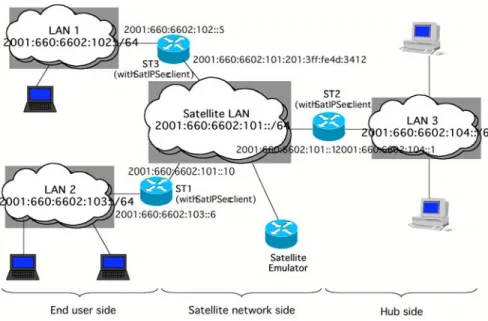
The testbed that has been developed is able to emulate the three main parts of a satellite communication system (SE, ST, NCC). It is described in Fig. 2. The middle side interconnects two user LANs (individual user, company subsidiaries …) involving a SubLAN, and the right LAN (LAN 3), acting as an Internet Service Provider site or as the company headquarters. LAN 3 provides also Internet interconnection, using native IPv6. Each LAN consists of one Satellite Terminal (ST), several user workstations (WS), no or one “ gateway” equipment (GW) associated with a specific terminal called GWS. Role and function are given in Table 1, related to the chosen validation scenario. The security scenario is mentioned in the last line.
SATLAN WS12 WS22 LAN2 ST2 WS13 LAN3 ST3 WS23 GW3 NCC Satellite Emulator IPv6 Backbone WS11 WS21 LAN1 SubLAN1 GWS11 SubLAN2 GWS12 GW2 GW1 ST1 GCKS (security scenario only)
Figure 2.Full SATIP6 testbed
ST WS GW GWS
Function Satellite terminal User workstation “Gateway” Specific terminal
QoS scenario With enabled QoS Server With enabled QoS Agent Not used Not used Multicast scenario With enabled mcastd With enabled mcastd Not used Not used
PEP scenario Basic configuration Not used PEP User terminal Mobility scenario Basic configuration Not used HA/Router User terminal Security scenario Basic configuration Not used SatIPSec client User terminal
Table 1 – Testbed components involved in validation scenario
D. SatIPSec Architecture
The security solution which has been implemented to protect satellite transmissions in the SATIP6 simulated architecture is a new layer 3 security solution called SatIPSec 2,3. This solution is based on two main entities entitled
SatIPSec client and SatIPSec Group Controller & Key Server (SatIPSec GCKS). The SatIPSec system
architecture is thus formed of several SatIPSec clients and of one GCKS. SatIPSec clients are in charge of securing IP traffic flows during their transmission over the satellite links. For that purpose, they apply some security treatments (ciphering/deciphering, computation and checking of authentication values…) to IP datagrams. The GCKS centrally ensures the management of SatIPSec clients and the establishment of the security architecture. Its function is to configure SatIPSec clients, by supplying them with the necessary information for securing data transmissions according to the data security requirements.
The Fig. 3 presents the security architecture defined in the SATIP6 project. SatIPSec clients and GCKS are implemented in external boxes (independently of the other Satcom equipments) ‡. There is one SatIPSec client box behind each Satellite Terminal (ST), and the GCKS is located at the gateway side.
The location of SatIPSec clients allows to apply security mechanisms to IP traffic (if requested) so as to ensure its protection during its transmission over the satellite network. In transmission, the SatIPSec client can cipher each IP packet and compute an authentication value before transmitting it on satellite system. In reception, the SatIPSec client(s) can decipher it and check the authentication value, before transmitting it on the terrestrial network it (they) is (are) connected to.
The implementation of the SatIPSec solution in the context of the SATIP6 project allows to protect any unicast or multicast IP flows transmitted on satellite links, from Hub to ST, from ST to Hub and from ST to ST (remark : multicast IP traffic is only generated at the Hub side).
IP packet IP packet IP packet IP packet IP packet IP packet
IP packet secured by SatIPSec solution SatIPsec client SatIPsec client SatIPsec client
End user End user End user Server GCKS IP packet IP packet IP packet ST ST ST IP packet
III.
SatIPSec solution implementation : general principles
A. Security Services
Here are described the security services offered by the SatIPSec solution implemented in the context of the SATIP6 project.
1. IP traffic protection
• Data confidentiality : achieved by the ciphering of the entire IP packet (data and header)
• Data integrity and Data origin authentication: achieved by the computation of an authentication value depending of the IP packet, before its transmission on satellite network. In reception SatIPSec clients can verify the integrity of the packet (i.e. if it has been modified or not during transmission) and the identity of its source, by checking its authentication value.
• IP address confidentiality: achieved by the ciphering of the entire IP packet (data and header) and its encapsulation into a new IP packet. The IP addresses of the initial packet are therefore encrypted. The source IP address of the new packet is the address of the SatIPSec client which has encapsulated the initial packet. The destination IP address is the address of the SatIPSec client which should desencapsulate the packet, or the initial multicast IP address in the case of a multicast packet.
• Traffic Processing per data flow: Each IP flow can be secured independently (with its own keys and security attributes), and encapsulated in its own IPSec tunnel. An IP data flow can be identified by its IP source and destination addresses (representing equipment, end-user, subnet, multicast IP address) and its source and destination port numbers. Thanks to this service, the access to a flow can easily be limited only to the allowed receivers.
These services can be offered simultaneously for all types of traffic (unicast and multicast). Besides SatIPSec allows one part of the traffic to be secured and the other part not.
2. Access control
Access control aims at guaranteeing that only authorized recipients get access to data transmitted on satellite links in clear. With SatIPSec, each IP flow requiring to be protected is encrypted before being transmitted on satellite network. The security parameters allowing to secure it in emission, and to decrypt it in reception, are distributed only to authorized SatIPSec clients. Thus SatIPSec solution enables a strong access control. All security parameters defining how to secure an IP flow (keys, cryptographic algorithms to use, flow identifier…) are contained in a Security Association (SA).
Access control is managed by the GCKS. It authenticates each SatIPSec client before distributing it, in a secure manner, only the Security Associations it is authorized to receive.
3. Centralized management
The SatIPSec implementation allows to establish and manage Virtual Private Networks (VPN) and Secure
Multicast Groups, in a centralized manner .
A VPN is established when two distant terrestrial sites wish to communicate securely together through the satellite network. A secure tunnel is established; its end-points are the SatIPSec clients connected to each site. This tunnel can be configured to secure for instance the exchanges between two end-users or subnets belonging to these sites, or all unicast traffic exchanged between these two sites.
A Secure Multicast Group is composed of members (i.e. SatIPSec clients) sharing a common security configuration allowing to secure IP multicast flows. Only group members can get access to the corresponding traffic (in clear) in reception. Each multicast IP packet is indeed encrypted and encapsulated before its transmission on satellite network by a group member. In reception, only group members can decipher it, and then transmit the packet on the terrestrial network they are connected to. The SatIPSec solution encapsulates multicast packets in new multicast packets, the establishment of a secure multicast group can therefore be considered as the establishment of multicast IPSec tunnels.
SatIPSec clients, VPNs and Secure Multicast Groups are managed by the GCKS. The establishment of a VPN or a Secure Multicast Group requires the selective distribution of the corresponding SAs by the GCKS (a SA contains all the necessary information to establish an IPSec tunnel to secure one unidirectional flow). For a VPN, both SAs (one for each direction) are transmitted only to the SatIPSec clients end-points of the VPN to establish. For a Multicast Secure Group, SAs (one for each multicast flow) are transmitted only to SatIPSec clients belonging to the group.
B. SatIPSec Functional architecture
As previously presented, two entity types are involved in SatIPSec: GCKS and SatIPSec clients. In the following their functional architecture and associated protocols are described.
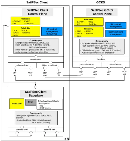
In IPSec, the data plane and the control plane are separated : the data plane implements the IPSec ESP protocol 5 or the IPSec AH 9 protocol, which are in charge of encrypting/decrypting and/or authenticating IP packets; the control plane implements the IKE 1 protocol, which is in charge of establishing and renewing IPSec SA between two equipments. In the same way, in SatIPSec, data plane and control plane are separated. The control plane implements a new protocol called Flat Multicast Key Exchange protocol (FMKE)4. It is a layer 3 protocol, mainly dedicated to group key and SA management. The data plane (in charge of encrypting and authenticating data) can be implemented at layer 2 or 3. In the implementation realized for the SATIP6 project, the selected data plane is the IPSec ESP protocol.
SatIPSec client and GCKS functional architectures are described in Fig. 4. SatIPSec Clients are composed of a control plane part and a data plane part. The data plane is managed by the control plane. The Client control plane is configured by the GCKS control plane.
C. Security Data plane
The selected security data plane is the ESP (Encapsulating Security Payload) protocol of IPSec. The ESP protocol is implemented and used as it is defined in the standard. ESP defines two IP packet secure encapsulations. In transport mode, the ESP header is inserted after the IP header and before the upper layer protocol header, and only the packet payload is encrypted. In tunnel mode, the ESP header is inserted before an encapsulated IP header, and both payload and header are encrypted and encapsulated in a new IP packet. The SatIPSec implementation enables the tunnel mode only.
In the implementation, confidentiality, data origin authentication and IP address confidentiality services are provided like in ESP, by using the same mechanisms. The cryptographic algorithms of the demonstrator are usually used with ESP: AES, 3DES, DES, Blowfish for the encryption algorithms, and HMAC-SHA1, HMAC-MD5 for integrity-source authentication algorithms
Sessions
Cryptography
- Encryption algorithms:DES, 3DES, AES - Hash algorithms: SHA-1(HMAC variant), MD5 (HMAC variant) - Diffie-Hellman : group 1(768 bits) & 2(1024bits) - Authentication method: pre-shared key
SatIPSec Client m anagement
SatIPSec GCKS Control Plane
Liaisons multicast Liaison unicast
Filter IPSec ESP Session client Liaisons multicast Liaison unicast UDP multi UDP multi UDP uni UDP uni UDP uni UDP uni UDP uni UDP uni
Ground Side Satellite side
SatIPSec Client x N Protocols - ISAK MP -FMKE - IKE - SatIPSec Reliability - ACK - SACK - NACK - windows - timer S A control/ management
Other functional blocks
- TCP spoofer - drop - IGMP proxy...
Cryptography
- Encryption algorithms:DES, 3DES, AES - Hash algorithms: SHA-1(HMAC variant), MD5 (HMAC variant) - Diffie-Hellman : group 1(768 bits) & 2(1024bits) - Authentication method: pre-shared key
SatIPSec Client Control Plane Protocols - ISAKMP -FMKE - IKE - SatIPSec Reliability - ACK - SACK - NACK - windows - timer SA control/ management (SAD, SPD) SatIPSec Client Dataplane Cryptography
- Encryption algorithms:DES, 3DES, AES , Blowfish...
- Hash algorithms: SHA-1(HMAC variant), MD5 (HMAC variant)
GCKS
D. Control plane : FMKE
The Flat Multicast Key Exchange (FMKE) protocol is a new group key management protocol, based on a centralized management achieved by the GCKS. Its objective is to manage securely Security Associations destined to protect multicast and unicast IP traffic, i.e. establish and update SAs in clients participating to Secure Multicast Groups and VPN. The FMKE protocol is in particular optimized for very large multicast groups in flat environment (i.e. no intermediate routers between GCKS and a large amount of clients) like in satellite networks. In fact, FMKE is derived from the Group Domain Of Interpretation (GDOI) protocol 10 defined by the IETF Multicast SECurity (MSEC) group, and can be seen as a use case adapted to satellite networks and to the needs of the SATIP6 project. There are three main differences. First of all, FMKE manages SAs for group and unicast exchanges, contrary to GDOI, which manages only groups, and requires therefore to add external mechanisms to establish VPNs. Secondly, FMKE exchanges implement reliability mechanisms based on positive, negative acknowledgements… in order to guaranty a reliable key distribution (in unicast and in multicast). GDOI does not guaranty at all reliable key distribution. At last, in GDOI, the client has to request to get access to a particular group in order to receive the corresponding SAs if it is authorized, while in FMKE, the client receives directly all SAs it is authorized to get access to, without having to send a request for each group. This way FMKE limits the consumed bandwidth. Indeed the client does not have to send a request for each group, and a FMKE message from the GCKS can contain SAs from different groups and VPNs. However, FMKE could be defined with a GDOI-like behavior.
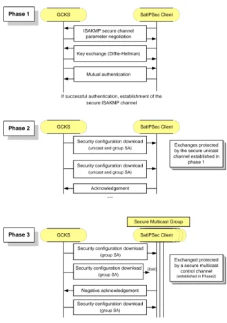
FMKE is thus used securely to configure SatIPSec clients with the necessary SAs to establish the required security architecture (i.e. VPNs, Secure Multicast Groups). Client configuration is achieved thanks to three different phases described in Ref. 4. The implementation achieved in the context of the SATIP6 project enables the two first ones.
The first phase is dedicated to the establishment of a secure ISAKMP 11 channel between the GCKS control plane and the client control plane. This establishment is preceded by a mutual authentication. In the SatIPSec implementation, the method which has been selected for this phase is the method called « Main-Mode with pre-Shared key for Authentication » defined in the IKE protocol 1(IKE phase 1). Authentication is based on a pre-shared secret.
The second phase is dedicated to the SatIPSec client configuration. The GCKS transmits to the client, SAs that it is authorized to receive. These SAs are sent securely in unicast, thanks to the secure ISAKMP channel established during the previous phase (confidentiality, data origin authentication and integrity are provided). SAs concerns VPN and Secure Multicast Groups.
The cryptographic methods and algorithms used in the SATIP6 demonstrator are Diffie-Hellman group 1 and group 2 for key exchange, DES, 3DES and AES for encryption, and SHA1, HMAC-MD5 for integrity/source authentication.
The FMKE third phase is dedicated to the configuration of a Secure Multicast Group (i.e. of its group members). The GCKS transmits, in multicast, to all group members, SAs allowing to secure multicast flows. These transmissions are protected by a secure multicast control channel dedicated to the group, whose parameters have been previously transmitted to each group member thanks to phase 2.
ISAKMP secure channel parameter negotiation
Key exchange (Diffie-Hellman)
Mutual authentication SatIPSec Client GCKS SatIPSec Client GCKS Acknowledgement GCKS Negative acknowledgement SatIPSec Client (lost) Secure Multicast Group ...
...
Exchanges protected by the secure unicast channel established in phase 1 Exchanged protected by a secure multicast control channel (established in Phase2) Phase 1 Phase 2 Phase 3
Security configuration download (unicast and group SA)
Security configuration download (group SA)
If successful authentication, establishment of the secure ISAKMP channel
Security configuration download (unicast and group SA)
Security configuration download (group SA)
Security configuration download (group SA)
Figure 5. FMKE phases
IV.
SatIPSec Implementation features
A. Equipment and software
SatIPSec client and GCKS control plane software modules are implemented in basic central units containing a 2G Intel Celeron processor. SatIPSec clients boxes are routers. The SatIPSec implementation uses software cryptographic algorithms only (no cryptohardware) .
The interface between control plane and data plane (IPSec ESP) relies on the PF_KEY API system 12 available on Unix platforms.
This demonstrator is based a customized version of the OpenBSD kernel. Some modifications have indeed been realized in the IP stack, in particular at multicast forwarding, routing, and IPSec levels.
The SatIPSec implementation has been developed to work in IPv4 and in IPv6.
B. SatIPSec System configuration and graphical interfaces
The initial configuration of both clients and GCKS is done thanks to configuration files. The configuration file of a SatIPSec client contains few information: its IP address, GCKS IP address, a secret shared only by itself and GCKS (for mutual authentication), and parameters for the ISAKMP secure channel to establish in phase 1. The GCKS configuration file contains a set of client IP address with shared secrets and client’s profile that defines the list of SAs each client is authorized to receive, and a list of SAs with their attributes. A graphical interface has been developed to facilitate the GCKS configuration. It creates automatically its configuration file, according to the information given by the security operator. The graphical interface is presented in Fig. 6 ‘GCKS configuration interface’, and is composed of three main parts :
• SatIPSec client configuration : this step consists of giving SatIPSec clients’ IP address and shared secret. • Secure Multicast Group configuration : this step consists of indicating the Secure Multicast Groups to establish.
clients, the identification of IP multicast flows to be secured by the group (multicast IP address, Source IP address, and source and destination port numbers), and for each identified flow, selection of the security parameters to use (encryption and integrity algorithms, key lifetime).
• VPN configuration : this step consists of indicating the VPNs to establish. The configuration of a VPN involves the selection of two SatIPSec clients as VPN tunnel end-points, the identification of the unicast flow to secure (source and destination IP addresses representing subnets or hosts, source and destination port numbers), and the security parameters to use (encryption and integrity algorithms, key lifetime).
Thanks to the information given by the security operator, the GCKS configuration file is built. SA cryptographic keys and SPI (Secure Parameter Index, i.e. SA identifier) are generated randomly.
The interface represented in Fig. 6 entitled ‘GCKS control interface’ allows to control during SatIPSec processing the connection status of each client with GCKS. This interface also indicates all the SAs (with their security attributes) which have to be established, and for each client, the list of SAs they are going to receive.
Figure 6. Graphical interfaces : GCKS configuration interface & GCKS control interface
V.
Demonstration
A. VPN and Secure Multicast Groups established
Three VPNs have been established on the simulated architecture: between each remote site and the Hub, securing all unicast bi-directional traffic exchanged respectively between LAN 3 and LAN 2, and LAN 3 and LAN 1, and between both remote sites, securing all unicast bi-directional traffic exchanged between LAN 2 and LAN 1 (Fig. 7).
Three different Secure Multicast Groups have been established, in order to limit the access to multicast flows only to the authorized remote sites. Multicast traffic is generated at the hub side only. The three groups obviously contain the SatIPSec client located at the Hub side, and respectively the client connected to LAN 1, the client connected to LAN 2, and the clients connected respectively to LAN 1 and to LAN 2. These multicast groups have allowed to secure video streaming sent in multicast, destined only to LAN 1, LAN 2, or both LAN 1 and 2.
B. Applications
Several unicast and multicast applications have been used to validate the SatIPSec demonstrator : • Video & Audio streaming : VideoLanClient (VLC)
VLC is a multimedia player for various media sources (DIVX files to DVDs) and a audio and video streaming server that supports a complete set of codecs, single or multiple diffusion (respectively unicast and multicast) and various protocols (IPv4 or IPv6, RTP, UDP …).
• Visioconferencing: Gnomemeeting and Linphone
Based on OpenH323, Gnomemeeting is an open source application that belongs to the scarce real-time conferencing tools for non-Windows operating systems that are interoperable with Windows based H323 clients like Netmeeting. IPv6 is supported since April 2003. Thus, Gnomemeeting receives and makes call over IPv6 and provides full and transparent backward compatibility with IPv4.
Linphone is a SIP compliant web phone that supports a large variety of audio codecs. Since its release 0.11.0, a patch provides full IPv6 support.
• HTTP: Apache HTTP Server and Mozilla HTTP client
Apache HTTP Server is an open-source HTTP Server that runs on Unix and Windows NT operating systems. Apache natively supports IPv6 since its release v2.0 and provides HTTP proxy functions that are required for the SatIP6 scenario.
The Mozilla 5.0 HTTP client natively supports IPV6. It can access IPv6-enabled Web servers. It uses IPv6 to download Web pages when the Domain Name System (DNS) query for the name of the Web server in the URL returns an IPv6 address.
• FTP: Vsftpd and ftp
Very Secured FTP daemon (vsftpd ) natively supports IPv6 in its release v1.2.0.
For Windows XP, the File Transfer Protocol (FTP) client can be used to establish FTP sessions with IPv4 and IPv6 FTP servers.
References
1 IKE 2 SatIPSec ka 3 SatIPSec ISSE 4 draft fmke 5 esp 6 website satip67 Ip dedicated 8 Brahms 9 ah 10 GDOI 11 ISAKMP 12