ÉCOLE DE TECHNOLOGIE SUPÉRIEURE UNIVERSITÉ DU QUÉBEC
MANUSCRIPT-BASED THESIS PRESENTED TO ÉCOLE DE TECHNOLOGIE SUPÉRIEURE
IN PARTIAL FULFILLMENT OF THE REQUIREMENTS FOR THE DEGREE OF DOCTOR OF PHILOSOPHY
Ph.D.
BY
Abdallah BEN MOSBAH
NEW METHODOLOGIES FOR CALCULATION OF FLIGHT PARAMETERS ON REDUCED SCALE WINGS MODELS IN WIND TUNNEL
MONTREAL, JANUARY 4TH, 2017 © Copyright 2016 reserved by Abdallah Ben Mosbah
© Copyright reserved
It is forbidden to reproduce, save or share the content of this document either in whole or in parts. The reader who wishes to print or save this document on any media must first get the permission of the author.
BOARD OF EXAMINERS (THESIS PH.D.) THIS THESIS HAS BEEN EVALUATED BY THE FOLLOWING BOARD OF EXAMINERS
Dr. Ruxandra Mihaela Botez, Thesis Supervisor
Department of Automated Production Engineering at École de technologie supérieure
Dr. Thien-My Dao, Thesis Co-supervisor
Department of Mechanical Engineering at École de technologie supérieure
Dr. Ammar Kouki, President of the Board of Examiners
Department of Electrical Engineering at École de technologie supérieure
Dr. Pascal Bigras, Member of the jury
Department of Automated Production Engineering at École de technologie supérieure
Dr. Nabil Nahas, External Evaluator
Department of System Engineering at King Fahd University of Petroleum and Minerals
THIS THESIS WAS PRENSENTED AND DEFENDED
IN THE PRESENCE OF A BOARD OF EXAMINERS AND PUBLIC MONTREAL, NOVEMBER 25TH, 2016
ACKNOWLEDGMENT
First, I thank God for his favors and gratitude to provide me the patience and knowledge to complete my dissertation.
It gives me particular pleasure, before presenting my work to express my gratitude to those near and far have given me their concern. I especially express my deep appreciation to my research supervisors, Ruxandra Botez and Thien-My Dao for their guidance and kindness throughout this work.
A special thanks to Mr. Nabil Nahas, Mr. Pascal Bigras and Mr Ammar Kouki for taking time to evaluate this work and to serve on my thesis committee.
I am very thankful to all my colleagues of LARCASE team for their helpful discussions.
I express a big thankful to my dear wife Soumaya and my siblings who supported, encouraged and helped me to cap off my thesis. I also thank all my friends for their confidence and support.
An enormous thanks to my parents, Salem and Om Essaed, for the support and love given to me to achieve my dream. I cannot thank them enough for all the sacrifices they made during every phase of this thesis. No reward or dedication cannot express my gratitude and deep respect and love.
Finally, I would like to dedicate this work to all my family especially to my children Iyess and Anas in spite of spending so much time away from them to achieve this work.
NOUVELLES MÉTHODOLOGIES DE CALCUL DES PARAMÈTRES DE VOL SUR DES MODÈLES DES AILES À L'ÉCHELLE RÉDUITE EN SOUFFLERIE
Abdallah BEN MOSBAH RÉSUMÉ
Dans le but d'améliorer les qualités de tests en soufflerie ainsi que les outils nécessaires pour réaliser des tests aérodynamiques sur des modèles d'ailes d'avions en soufflerie, des nouvelles méthodologies ont été développées et testées sur des modèles d'ailes originales et déformables. Un concept d'aile déformable consiste à remplacer une partie (inférieure et/ou supérieure) de la peau de l'aile par une autre partie flexible dont sa forme peut être modifiée à l'aide d'un système d'actionnement installé à l'intérieur de l'aile. Le but d'utiliser ce concept est d'améliorer les performances aérodynamiques de l'avion et surtout de réduire sa consommation de carburant. Des analyses numériques et expérimentales ont été effectuées afin de développer et de tester les méthodologies proposées dans cette thèse.
Dans l'objectif de contrôler l'étalonnage de la soufflerie Price-Païdoussis de LARCASE, des analyses numériques et expérimentales ont été réalisées. Des calculs par éléments finis ont été faits pour construire une base de données permettant de développer une nouvelle méthodologie hybride d'étalonnage. Cette nouvelle approche a permis de contrôler l'écoulement d'air dans la chambre d'essais de la soufflerie Price-Païdoussis.
Pour la détermination rapide des paramètres aérodynamiques, des nouvelles méthodologies hybrides ont été proposées. Ces méthodologies ont été utilisées pour le contrôle des paramètres de vol par la détermination des coefficients de traînée et de portance, de moment de tangage ainsi que de la distribution de pression autour d'un profil d'aile d'avion. Ces coefficients aérodynamiques ont été calculés à partir des conditions d'écoulement connues comme l'angle d'attaque, le nombre de Mach et le nombre de Reynolds.
Dans le but de changer la forme de la peau de l’aile, des actionneurs électriques ont été installés à l'intérieur de l'aile pour modifier sa surface supérieure et pour avoir la forme désirée. Cette déformation permet d'obtenir les profiles optimales en fonction de différentes conditions de vol afin de réduire la consommation de carburant de l'avion. Un contrôleur basé sur des réseaux de neurones a été mis en œuvre afin d'obtenir les déplacements souhaités des actionneurs.
Un algorithme d'optimisation métaheuristique a été utilisée en hybridation avec des réseaux de neurones ainsi qu'avec une approche machine à vecteurs de support. Leur combinaison a été optimisée et de très bons résultats ont été obtenus dans un temps de calcul réduit.
La validation des résultats obtenus par la combinaison de ces techniques a été réalisée à l'aide des données numériques du code XFoil et aussi avec le logiciel de simulation numérique
VIII
Fluent. Les résultats obtenus à l'aide des méthodologies présentées dans cette thèse ont été aussi validés par des essais expérimentaux dans la soufflerie subsonique Price-Païdoussis. Mots clés: analyse aérodynamique, optimisation, intelligence artificielle, aile déformable, validation expérimentale
NEW METHODOLOGIES FOR CALCULATION OF FLIGHT PARAMETERS ON REDUCED SCALE WINGS MODELS IN WIND TUNNEL
Abdallah BEN MOSBAH ABSTRACT
In order to improve the qualities of wind tunnel tests, and the tools used to perform aerodynamic tests on aircraft wings in the wind tunnel, new methodologies were developed and tested on rigid and flexible wings models. A flexible wing concept is consists in replacing a portion (lower and/or upper) of the skin with another flexible portion whose shape can be changed using an actuation system installed inside of the wing. The main purpose of this concept is to improve the aerodynamic performance of the aircraft, and especially to reduce the fuel consumption of the airplane. Numerical and experimental analyses were conducted to develop and test the methodologies proposed in this thesis.
To control the flow inside the test sections of the Price-Païdoussis wind tunnel of LARCASE, numerical and experimental analyses were performed. Computational fluid dynamics
calculations have been made in order to obtain a database used to develop a new hybrid methodology for wind tunnel calibration. This approach allows controlling the flow in the test section of the Price-Païdoussis wind tunnel.
For the fast determination of aerodynamic parameters, new hybrid methodologies were proposed. These methodologies were used to control flight parameters by the calculation of the drag, lift and pitching moment coefficients and by the calculation of the pressure distribution around an airfoil. These aerodynamic coefficients were calculated from the known airflow conditions such as angles of attack, the mach and the Reynolds numbers. In order to modify the shape of the wing skin, electric actuators were installed inside the wing to get the desired shape. These deformations provide optimal profiles according to different flight conditions in order to reduce the fuel consumption. A controller based on neural networks was implemented to obtain desired displacement actuators.
A metaheuristic algorithm was used in hybridization with neural networks, and support vector machine approaches and their combination was optimized, and very good results were obtained in a reduced computing time.
The validation of the obtained results has been made using numerical data obtained by the XFoil code, and also by the Fluent code. The results obtained using the methodologies presented in this thesis have been validated with experimental data obtained using the
subsonic Price-Païdoussis blow down wind tunnel.
Keywords: aerodynamic analyses, optimization, artificial intelligence, morphing wing, experimental validation
TABLE OF CONTENTS
INTRODUCTION ...1
CHAPTER 1 LITTERATURE REVIEW ...13
1.1 Hybrid Approaches ...13
1.1.1 Neural Networks and Fuzzy Logic ... 13
1.1.2 Artificial intelligence and optimization algorithms ... 14
1.1.2.1 The Simulated Annealing ... 15
1.1.2.2 The Genetic Algorithm ... 16
1.2 Neural Networks in Wind Tunnel Applications ...17
1.3 Support Vector Machines ...20
CHAPTER 2 APPROACH AND THESIS ORGANIZATION ...23
2.1 Thesis Research Approach ...23
2.2 Thesis Organization ...24
2.2.1 First journal paper ... 25
2.2.2 Second journal paper ... 25
2.2.3 Third journal paper ... 26
2.2.4 Fourth journal paper ... 26
CHAPTER 3 ARTICLE 1: NEW METHODOLOGY FOR WIND TUNNEL CALIBRATION USING NEURAL NETWORKS - EGD APPROACH ...29
3.1 Introduction ...31
3.2 Subsonic wind tunnel ...32
3.3 Flow characterisation ...35
3.3.1 The Log-Tchebycheff Method ... 36
3.4 Extended great deluge technique ...38
3.5 Neural network approach ...41
3.5.1 Implementation of neural networks and Preliminary results: ... 43
3.6 Conclusion ...45
CHAPTER 4 ARTICLE 2: A HYBRID ORIGINAL APPROACH FOR PREDICTION OF THE AERODYNAMIC COEFFICIENTS OF AN ATR-42 SCALED WING MODEL ...47
4.1 Introduction ...48
4.2 Support vector machines (SVM) ...51
4.3 Optimization of the SVM parameters ...53
4.4 Extended great deluge algorithm ...54
4.5 New proposed SVM-EGD algorithm ...57
4.6 Infrastructure ...58
4.6.1 Price-Païdoussis wind tunnel ... 58
4.6.2 Transducer ... 60
4.6.3 ATR-42 wing ... 61
4.7 Implementation of the SVM-EGD algorithm and analysis of results ...62
XII
4.7.2 Experimental results... 66
4.8 Conclusions ...74
CHAPTER 5 ARTICLE 3: NEW METHODOLOGY COMBINING NEURAL NETWORK AND EXTENDED GREAT DELUGE ALGORITHMS FOR THE ATR-42 WING AERODYNAMICS ANALYSIS ...75
5.1 Introduction and background ...76
5.2 Flight parameters ...81
5.3 XFOIL code ...82
5.4 Neural networks ...82
5.5 EXTENDED GREAT DELUGE ...84
5.6 NN-EGD ALGORITHM ...86
5.7 Implementation of NN-EGD and theoretical results ...87
5.7.1 The CL, CD and CM prediction system ... 89
5.7.2 The Cp prediction system ... 94
5.8 Experimental tests ...97
5.8.1 Equipment ... 97
5.9 Experimental results...100
5.10 Conclusion ...107
CHAPTER 6 ARTICLE 4: A NEURAL NETWORK CONTROLLER FOR ATR-42 MORPHING WING ACTUATION ...109
6.1 Introduction ...110
6.2 ATR-42 Morphing Wing Model ...112
6.3 The closed loop architecture of the model ...114
6.3.1 Controller architecture ... 114
6.3.2 Modeling of the DC motor ... 115
6.4 Neural Network Control System Design ...118
6.5 Experimental work ...124
6.5.1 Concept of the experimental work ... 124
6.5.2 Experimentation and real time validation ... 125
6.5.2.1 Hardware ... 125
6.5.2.2 Real-Time Model ... 126
6.5.2.3 Validation Results ... 127
6.5.3 Wind tunnel test ... 128
6.5.3.1 Experimental test equipment... 128
6.5.3.2 Experimental results... 130
6.6 Conclusion ...132
DISCUSSION OF RESULTS...133
CONCLUSION AND RECOMMENDATIONS ...139
LIST OF TABLES
Page
Table 0.1 Geometry of the ATR 42 wing models...3
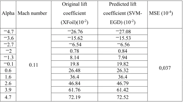
Table 4.1 Original versus predicted lift coefficients for different airflow cases. ... 63
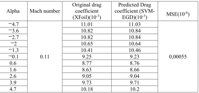
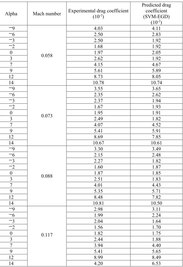
Table 4.2 Original versus predicted drag coefficients for different airflow cases. ... 64
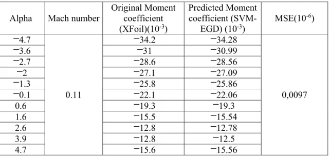
Table 4.3 Original versus predicted moment coefficients for different airflow cases. ... 65
Table 4.4 Experimental versus predicted lift coefficients for different airflow cases. ... 68
Table 4.5 Experimental versus predicted drag coefficients for different airflow cases. ... 70
Table 4.6 Experimental versus predicted moment coefficients for different airflow cases...72
Table 4.7 The obtained mean squared errors. ... 73
Table 5.1 Neural network architecture for CL, CD and CM prediction ... 89
Table 5.2 Lift coefficients variation with the angle of attack ... 92
Table 5.3 Drag coefficients variation with the angle of attack ... 92
Table 5.4 Moment coefficients variation with the angle of attack ... 93
Table 5.5 Neural network architecture for Cp prediction ... 95
Table 5.6 Location of pressure taps along the chord ... 100
Table 5.7 Cp values residual error between the NN-EGD, XFoil and experimental results for α=2.3o ... 101
Table 5.8 Cp values residual error between the NN-EGD, XFoil and experimental results for α=-2o ... 101
Table 5.9 Test parameters ... 103
Table 5.10 The residual error between the NN-EGD method and the experimental results...103
Table 6.1 Internal Motor Characteristics ... 118
XIV
Table 6.3 ''Current controller'' database ... 121 Table 6.4 List of the hardware used in the experiment ... 125 Table 6.5 Location of pressure taps ... 130
LIST OF FIGURES
Page
Figure 0.1 Reduced scale of the original wing model of an ATR 42 aircraft...2
Figure 0.2 Original and optimized ATR 42 profile...3
Figure 0.3 General Architecture of an Artificial Neuron...6
Figure 0.4 General Principle of the SVM...7
Figure 0.5 , * i i ζ ζ variation in non-linear regression...8
Figure 0.6 Price-Païdoussis Subsonic Blow Down Wind Tunnel...12
Figure 3.1 Wind tunnel sections ... 33
Figure 3.2 Wind tunnel measurement ... 33
Figure 3.3 Double impeller centrifugal fan ... 34
Figure 3.4 Settling sections ... 35
Figure 3.5 60 points traverse plane ... 37
Figure 3.6 Test section calibration ... 37
Figure 3.7 Pitot tube device ... 38
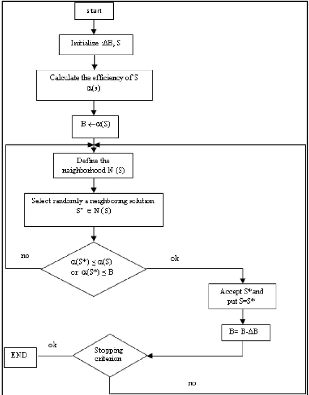
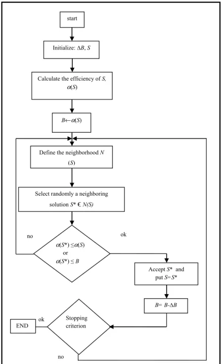
Figure 3.8 General flowchart of the EDG Taken from Ben Mosbah and Dao (2011) ... 40
Figure 3.9 Neural approach chart ... 42
Figure 3.10 Configuration of used NN taken from Matlab ... 43
Figure 3.11 Full mesh of ATR42 profile ... 44
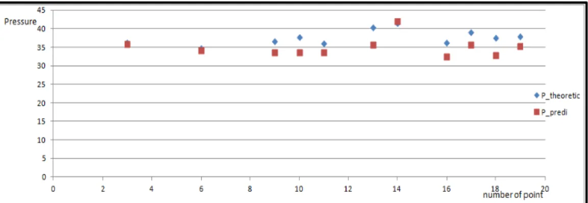
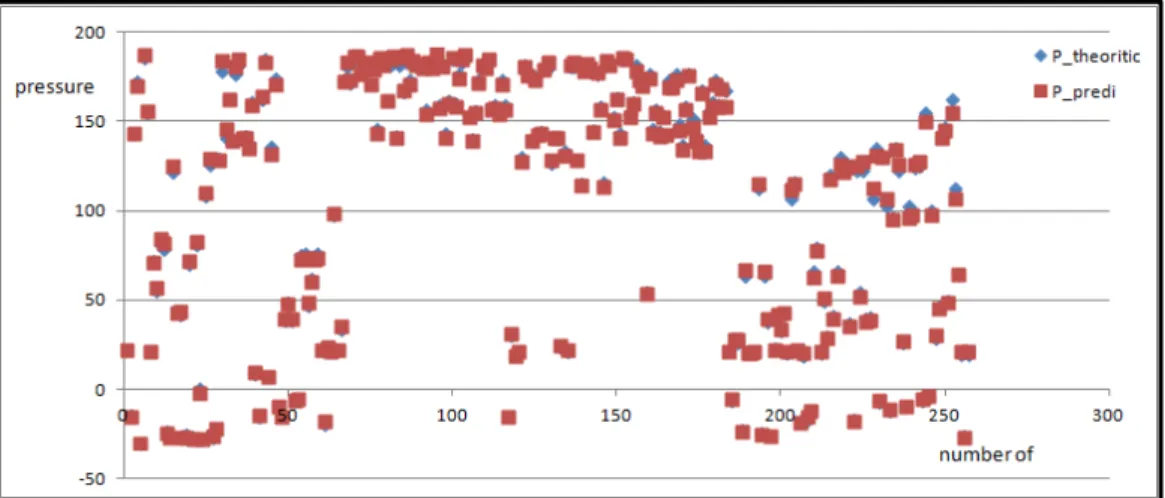
Figure 3.12 Comparison of pressure theoretic and pressure predict for plane 1... 44
Figure 3.13 Comparison of pressure theoretic and pressure predict for plane 2... 45
Figure 3.14 Comparison of pressure theoretic and pressure predict for plane 10... 45
Figure 4.1 Extended great deluge algorithm Take from Ben Mosbah and Dao (2011) ... 56
XVI
Figure 4.3 Hybrid SVM-EGD algorithm
Taken from Ben Mosbah et al. (2014) ... 59
Figure 4.4 Transducer ... 60
Figure 4.5 Fastening system of the model and transducer ... 61
Figure 4.6 ATR-42 model installed in the test chamber of the wind tunnel ... 62
Figure 4.7 Lift coefficient CL versus angle of attack ... 64
Figure 4.8 Drag coefficient CD versus angle of attack ... 65
Figure 4.9 Moment coefficient CM versus angle of attack ... 66
Figure 4.10 Lift aerodynamic coefficients variation versus angle of attack ... 69
Figure 4.11 Drag aerodynamic coefficients variation versus angle of attack ... 71
Figure 4.12 Moment aerodynamic coefficients variation versus angle of attack ... 73
Figure 5.1 Architecture of an artificial neuron... 83
Figure 5.2 General flowchart of the EGD algorithm Taken from Ben Mosbah and Dao (2011) ... 85
Figure 5.3 Proposed algorithm ... 88
Figure 5.4 Predictions systems ... 89
Figure 5.5 Neural Network architecture for the NN-EGD_pred1 model ... 90
Figure 5.6 Lift coefficient versus angle of attack ... 92
Figure 5.7 Drag coefficient versus angle of attack ... 93
Figure 5.8 Moment coefficient versus angle of attack ... 94
Figure 5.9 Neural architecture of the NN_pred2 model ... 95
Figure 5.10 Pressure coefficient distribution versus the chord for the angle of attack α=-2o ... 96
Figure 5.11 Pressure coefficient distribution versus the chord for the angle of attack α=3o ... 96 Figure 5.12 Pressure coefficient distribution versus the chord for the
XVII
Figure 5.13 Pressure coefficient distribution versus the chord for the
angle of attack α=3o ... Erreur ! Signet non défini. Figure 5.14 Price-Païdoussis wind tunnel ... 98 Figure 5.15 Model of the composite wing ATR-42 ... 98 Figure 5.16 Airfoil of the ATR-42 wing ... 99 Figure 5.17 NN-EGD, XFoil and wind tunnel tests results (by use of FLowKinetics system)
for Cp for the angle of attack α=2.3o ... 102 Figure 5.18 NN-EGD, XFoil and wind tunnel tests results (FLowKinetics) for Cp for the
angle of attack α=-2 ... 102 Figure 5.19 NN-EGD and experimental results (PTA & Multitube manometer) of Cp for
angle of attack α=0o and Reynolds number=539470 ... 104 Figure 5.20 NN-EGD and experimental results (PTA & Multitube manometer) of Cp for
angle of attack α=0o and Reynolds number =485520 ... 104 Figure 5.21 NN-EGD and experimental results (PTA & Multitube manometer) of Cp for
angle of attack α=1o and Reynolds number =539470 ... 104 Figure 5.22 NN-EGD and experimental results (PTA & Multitube manometer) of Cp for
angle of attack α=1o and Reynolds number =485520 ... 105 Figure 5.23 NN-EGD and experimental results (PTA & Multitube manometer) of Cp for
angle of attack α=1o and Reynolds number =431573 ... 105 Figure 5.24 NN-EGD and experimental results (PTA & Multitube manometer) of Cp for
angle of attack α=2o and Reynolds number =539470 ... 106 Figure 5.25 NN-EGD and experimental results (PTA & Multitube manometer) of Cp for
angle of attack α=2o and Reynolds number =485520 ... 106 Figure 5.26 NN-EGD and experimental results (PTA & Multitube manometer) of Cp for
angle of attack α=2o and Reynolds number =431573 ... 106 Figure 5.27 NN-EGD and experimental results (PTA & Multitube manometer) of Cp for
angle of attack α=-2o and Reynolds number =539470 ... 106 Figure 5.28 NN-EGD and experimental results (PTA & Multitube manometer) of Cp for
angle of attack α=-2o and Reynolds number =485520 ... 107 Figure 5.29 NN-EGD and experimental results (PTA & Multitube manometer) of Cp for
XVIII
Figure 6.1 CAD of the ATR-42 model ... 113
Figure 6.2 ATR-42 airfoil ... 113
Figure 6.3 Architecture of the closed loop system control ... 114
Figure 6.4 Closed loop control ... 115
Figure 6.5 Representation of the DC motors ... 115
Figure 6.6 Control system architecture ... 119
Figure 6.7 Used data to train the position controller ... 120
Figure 6.8 Used data to train the current controller ... 121
Figure 6.9 NNs’ architecture of the position controller ... 122
Figure 6.10 NNs’ architecture of the current controller ... 122
Figure 6.11 Response position using PID versus NNs (degree/time (s)) ... 123
Figure 6.12 Validation concept ... 124
Figure 6.13 Hardware installation ... 125
Figure 6.14 Simulink / Labview real-time model ... 127
Figure 6.15 Experimental results ... 128
Figure 6.16 Price-Païdoussis wind tunnel ... 129
Figure 6.17 ATR-42 morphing wing model ... 129
Figure 6.18 Multitube manometer tubes transducer ... 130
Figure 6.19 Experimental results (multitube manometer) of pressure coefficients Cp is for the angle of attack α=0o and Mach number=0.08 ... 131
Figure 6.20 Experimental results ( multitube manometer) of pressure coefficients Cp is for the angle of attack α=2o and Mach number=0.08 ... 131
Figure 6.21 Experimental results (multitube manometer) of pressure coefficients Cp is for the angle of attack α=-2o and Mach number=0.08 ... 132
LIST OF ABREVIATIONS
NN Neural Network
ANN Artificial Neural network
EGD Extended Great Deluge
WTTs Wind Tunnel Tests
CFD Computational Fluid Dynamics LVDT Linear Variable Differential Transformer PID controller Proportional-Integral-derivative controller
SVM Support Vector machines
SA Simulated Annealing
GA Genetic Algorithm
mVGA Multi-frequency Vibrational Genetic Algorithm
AI Artificial Intelligence
SISO Single Input Single output
AoA Angle of Attack
UAVs Unmanned Aircraft Vehicles SCR Silicon-controlled-Rectifier CEA Centroids of Equal Area
MAV Micro Air Vehicle
MSE Mean Squared Error
ANCAR Adaptive Neural Control of Aeroelastic Response BACT Benchmark Active Controls Technology
DLL Dynamic Link Library
HIL Hardware In the Loop PTA Pressure Transducer Array
LIST OF SYMBOLS X Input Vector W Weight Vector n Number of inputs b Threshold Y Output f Activation function s Number of neurons xn nth input yn nth output
|e| Error between the prediction value and the target
ε
Width of the tube defined around the desired outputsh SVM predicted function
C Regularization parameters
*
,
i i
ξ ξ Variation of samples that are outside of the
ε
-tubleK Kernel function
ai, ai* Lagrangian multipliers
B Limit pushing the research process to be made in one side of the
research space
S0 Initial solution
N(s) Neighborhood solution set
ΔB EGD input parameter (step used to decrease the limit B)
S Random solution
α Efficiency of the solution S N Neighborhood solutions of S.
S* Neighboring solution randomly selected from the set N ti Original value of the data point i
V Wind velocity
T Neural inputs
XXII
CD Drag coefficient
CM Pitching moment
Cp Pressure coefficient
Alpha Angle of attack
Ma Mach number Re Reynolds number U Voltage Rm Resistance L Inductance im Curent T0 Torque Em Counter-electromotive force
Wm Motor angular speed
ke angular speed constant
kf friction coefficient
TL Load torque
INTRODUCTION
Designing an aircraft requires solid knowledge of the various loads to be supported by the aircraft in flight. These loads are characterized by forces and constraints applied to the body of the aircraft based on flight conditions. Flight parameters such as pressure distribution and aerodynamic coefficients (lift, drag and moment) can be estimated from known parameters such as the angle of attack, the speed…etc. However, an accurate determination of these parameters is always difficult to achieve by numerical analysis methods, as they require long computing times for each flight case. These methods are generally validated by experimental tests in a wind tunnel and/or by flight tests. In addition, there are conventional flight parameter measurement methods use sensors installed directly on the aircraft body. Both of these methods and techniques can be very cumbersome, especially for smaller airplanes or UAVs. An efficient, simpler prediction system for determining these aerodynamic parameters would be a major advantage. This system would need to be tested and validated in a wind tunnel before moving to flight tests.
0.1 Motivation and Problem Statement
Calculating aerodynamic parameters is always a difficult task, especially under critical flight conditions such as stall phenomenon, icing, maneuvers, etc. In addition to these difficulties, the uncertainties of conventional measurement techniques adds to the uncertainly due to the installation of sensors outside on the aircraft. These uncertainties are generated by the structural aging process, rain, dust, and insect impacts that occur during flight, which may cause changes in the surface texture (Abha et al., 2000). Therefore, to eliminate or minimize these problems, techniques and hybrid approaches for designing control systems were developed to improve the precise determination of flight parameters.
2
0.1.1 ATR-42 morphing project
Launched in 2012 at the Applied Research Laboratory in Active Controls, Avionics and Aeroservoelasticity (LARCASE), the objective of the ATR-42 project was to optimize, design and manufacture an ATR-42 wing model, and to validate it experimentally in the Price-Païdoussis wind tunnel at the LARCASE (Figure 0.1). Three airfoil wing models were manufactured during the project. The first one was an original airfoil of an ATR-42 airplane, the second an optimized aerodynamic airfoil on which the drag was calculated to decrease when the angle of attack was 0o and the Mach number was 0.1; both wing models with a rigid upper surface. The third model was a morphing wing whose upper surface was morphed using an actuation system installed inside the model. Figure 0.2 shows the original and the optimized ATR-42 aircraft airfoils. The geometric details of the three models are presented in Table 0.1.
Figure 0.1 Reduced scale of the original wing model of an ATR 42 aircraft
3
Figure 0.2 Original and optimized ATR 42 profile
Table 0.1 Geometry of the ATR 42 wing models
Original ATR 42 Optimized ATR 42 Morphed ATR 42
Chord 247 mm 258 mm 245 mm
Wingspan 610 mm 610 mm 600 mm
Maximum thickness 25 mm 27 mm 28 mm
0.2 Objectives
This thesis presents the work of designing and optimizing methodologies to control, predict and improve aerodynamic parameters and their performances on a wing-tip model. These methodologies were validated by numerical simulation and by experimental tests using wind tunnel test data.
The following sub-objectives were established as a means to achieve the research objectives: Prediction of the pressure distribution in the test chamber section of the
Price-Païdoussis Wind Tunnel of the LARCASE laboratory during the calibration phase.
The NN-EGD (Neural Network - Extended Great Deluge) methodology to control pressure in the test chamber ensured the control and good functioning of the wind tunnel before WTTs and in real time during wind tunnel tests without applying CFD methods. The NN-EGD methodology was designed for the ATR-42 reduced-scale wing model and further tested in the Price-Païdoussis wind tunnel.
4
Development of new prediction methodologies to calculate aerodynamic lift, drag and moment coefficients, as well as the pressure distribution around a reduced-scale wing of an ATR-42 airplane.
These methodologies were designed based on new ''hybrid'' approaches and validated both by numerical simulations using XFoil solver and by experimental tests using the Price-Païdoussis subsonic blow down wind tunnel.
The control of actuators using a new methodology based on ''supervised learning'' to modify the shape of the upper surface of morphing wing. These actuators were fixed inside the reduced-scale wing of an ATR-42 aircraft.
The validation of this control was done in the Price-Païdoussis wind tunnel, and these experimental results were compared and validated with the PID controller results.
0.3 Methodology
This research presents a regression problem where the desired results are real. There are many supervised learning methods with which to approach this problem, such as neural networks (NNs) (Lettvin et al., 1959), Support Vector Machines (SVM) (Vapnik, 1999), Learning Automata (Kumpati and Thathachar, 1974), and Boosting (Kearns and Valiant, 1989).
As part of elaborating our methods, the solutions utilized to reach our goals are presented; mainly the optimization algorithms and the validation methods and tools.
The following methods and tools were used to achieve the sub-objectives specified above: In the ATR-42 project:
• Development of a hybrid approach based on Artificial Neural Networks (ANNs) and the Extended Great Deluge (EGD) optimization algorithm to solve the problem of the Price-Païdoussis wind tunnel calibration at the Applied Research Laboratory in Active Controls, Avionics and Aeroservoelasticity (LARCASE);
5
• The design of a hybrid model based on Support Vector Machines (SVM) and the EGD optimization algorithm to estimate aerodynamic coefficients (lift, drag and moment coefficients);
• The design of a hybrid approach based on ANNs and an optimization algorithm to predict the lift, drag and moment coefficients as well as the pressure distribution;
• The EGD algorithm to optimize the SVM and ANNs approaches;
• XFoil and FLUENT aerodynamic solvers for numerical simulations; the results obtained were then compared to the experimental Wind Tunnel Tests results;
• The design of a new methodology based on ANNs and EGD for the control of actuators to modify the shape of the upper surface of the reduced-scale morphing wing of an ATR-42 aircraft; and
• The validation of the proposed numerical approaches using Price-Païdoussis wind tunnel tests.
These methods and tools are described in the following paragraphs. Matlab/Simulink software was used for programming and testing of the proposed approaches.
0.3.1 Artificial Neural Networks (ANNs)
ANNs offer an approach that has been widely used to solve ''classification'' or ''prediction'' and ''estimation'' problems in various fields, especially in aeronautics, including fault detection, flight trajectories simulation, control, and autopilot scenarios.
ANNs are a processing structure distributed in a parallel scheme. A Neural Network is constituted by interconnected processing units called ''neurons''. Each neuron sends a
6
weighted function of its inputs in a layer to the outputs that are expressed by neurons in the next layer (Abha et al., 2000). Figure 0.3 shows a general representation of an artificial neuron. Each element of the input vector X: x1, x2,…, xn is multiplied by the corresponding weight vector W: w1,1, w1,2,..., w1,n (n is the number of inputs). A bias b is added to the neuron inputs; the input of each neuron can be written as follows:
1 1,1 2 2,1 ,1
. . . ... n. n
m = X W + =b x w +x w + +x w +b (0.1) An activation function f’ is then applied, as shown in Figure 0.3. The output value is given in the following form:
y f XW b
=
( .
+
)
(0.2)Figure 0.3 General architecture of an artificial neuron
When a number of neurons s exists in one layer, the weight W has the size (n x s). The same principle is applied in multi-layer models. The function given by Equation (0.2) can thus be written under the following matrix form:
(
)
1,1 1,2 1, 1 2,1 2,2 2, 2 1 2 ,1 ,2 , ... ... ... ... s s i n s n n n s w w w b w w w b y f x x x b w w w = + (0.3)7
The activation function f is used to calculate the input of each neuron yi. It serves to introduce a
non-linearity in the neuron function. Two classic functions, the hyperbolic tangent sigmoid (Equation 0.4 ) and the logarithmic sigmoid (Equation 0.5) are the functions used most often:
2 ( ) 1 1 exp( 2 * ) f m m = − + − (0.4) ( ) 1 1 exp( ) f m m = + − (0.5) where m X W b= . +
0.3.2 Support Vector Machines
Methodologies designed based on Support Vector Machine (SVM) algorithms are based on ''Supervised Learning''. The training process is done automatically, according to rules from a database of already-treated examples. These examples are characterized by inputs xn and their desired outputs yn , where yn=f(xn) (Figure 0.4). The regression problem is to find a function h that is as close as possible to the target f. The error e = h(xn) - f(xn) is minimized by using an insensitive loss parameter Ins e( ) max(0,= e − . The parameter Ins(e) is equal to zero ε) when e is less than
ε
(Pannagadatta et al., 2007) (Figure 0.5).Figure 0.4 General principle of the SVM
When the error e falls between the prediction function h and the target f is greater than the
ε
value, the function h is estimated using the form below (Cornuejols et al., 2002):( ) .
h x = w x b+ (0.6) where w is the weight of the inputs’ space and b is a threshold ∈R.
8
For linear regression, considering a set of data {x1, x2,..., xn} with target values {y1, y2,..., yn}, the optimization of the prediction function h is characterized by the resolution of the following formulation (Vapnik, 1999):
min 2 * 1 1 ( ) 2 n i i i w C
ζ ζ
= +
+ (0.7) subject to:y
i−
wx b
i− ≤ +
ε ζ
i∀ =
i
1,2,...,
n
(0.8) * 1, 2,..., i i i wx + − ≤ +b yε ζ
∀ =i n (0.9)ζ ζ
i, i* ≥0 ∀ =i 1, 2,...,n (0.10) where:• C is a regularization parameter, which can control the influence of the error; • The term 1 2
2 w is used to control the complexity of the regression function; and
• ɛ is the width of the tube defined around the desired outputs, with , *
i i ξ ξ the variations of samples that are outside of the ε-tube (Figure 0.5).
Figure 0.5 *
,
i i
ζ ζ variation in non-linear regression Taken from Vojislav (2001)
9
For a non-linear regression, a kernel function K(x,xi) is used in the linear model shown below. By introducing Lagrangian multipliers ai and ai* for Equations (0.8) and Equation (0.9), the new regression formulation can be expressed as follows (Smola and Schölkopf, 2004): * 1 ( ) n ( i i) ( , )i i h x a a K x x b = =
− + (0.11) where:• ai and ai* (0 ≤ ai , ai* ≤ C) are the Lagrange multipliers, which are calculated in the training process;
• n is the subset of the samples; and
• K is the kernel function. Some examples of kernel function are (El Asli, 2008):
-Linear kernel function: K(x,x’)=x.x’ ;
-Polynomial kernel function: K(x,x’)=(x.x’)d ; and -Gaussian kernel function: K(x,x’)=
2 2 ' exp 2 x x σ − −
0.3.3 The Extended Great Deluge Optimizer
The Extended Great Deluge (EGD) optimizer is a local search procedure that was introduced by Dueck in 1993. It is considered a local search algorithm for which some bad solutions whose values do not exceed a certain limit B are accepted. This limit B was decreased (in the case of minimization problems) monotonically during the search, while it was increased in the case of maximization problems. The increase/decrease is represented by ΔB. The ΔB step represents an input parameter for this approach. The limit B serves to push the solution towards the feasible space. In other words, the limit B cuts the neighborhood of the solution so that the research is done on only one side, below the limit B in the case of minimization problems or above the limit B in the case of maximization problems. This control process gives the desired solution.
10
In the beginning of a search process, the solution has the ability to move in both directions within the feasible portion limited by B. Otherwise, wrong responses may be obtained because the limit B is located at a long distance from the chosen solution, where a small part of the neighborhood has been cut. During this search, the limit B moves closer to the solution value, the search space becomes smaller and there is a lower possibility of improving the solution, leading to the end of the search (Ben Mosbah and Dao, 2013). The algorithm’s steps as presented by Burke et al. (2004) are:
Set the initial solution S0;
Calculate the initial cost function f(S0); Set the initial ceiling B=f(S0);
Specify the input parameter ΔB=?;
While not meeting some stopping criteria do Define neighborhood N(S)
Randomly select the candidate solution S* ∈ N(S) Calculate f(S*) If (f(S*) ≤ f(S)) or (f(S*) ≤ B) Accept S* and B = B –∆B End If ; then End While. 0.3.4 XFoil solver
XFoil is a bi-dimensional aerodynamic analysis code, developed by Drela and Giles in 1987. Here it was used to calculate and analyze the aerodynamic coefficients for a wing airfoil. XFoil solver gives a good prediction of the laminar/turbulence flow region, and of the drag and lift load results. To validate the performance of XFoil solver, the results of an analysis were compared with a set of experimental wind tunnel tests at cruise condition conducted by Helge and Antonino (1995). The comparison showed that XFoil obtained acceptable aerodynamic coefficients.
11
The XFoil solver was selected because of its computational speed compared to other CFD software. The XFoil results can be coupled with an optimization algorithm for airfoil morphing (Daniel et al., 2010).
0.3.5 Fluent solver
The numerical simulations of the 3-dimensional model were done using the ANSYS Fluent software. This CFD software is a fluid dynamics tool used to model flow, turbulence, heat transfer, etc. A turbulence model (Florian, 2009) was coupled with a laminar/turbulence transition model (Florian et al., 2006) to perform the numerical analysis. The ANSYS Fluent
software has been used in various industrial applications, such as in the aerodynamic modeling around an airplane wing.
0.3.6 The wind tunnel
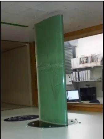
The proposed models were validated using experimental tests carried out in the Price-Païdoussis wind tunnel. This subsonic blow down wind tunnel (Figure 0.6) is available at the Applied Research Laboratory in Active Controls, Avionics and Aeroservoelasticity (LARCASE) and is equipped with two test chambers. The dimension of the, smaller test chamber is 0.3 x 0.6 x 0.9 m3. The wind tunnel can produce air speed up to 60 m/s in this smaller test chamber. The larger test chamber has a section equal to 0.6 x 0.9 x 1.82 m3, and provides an air speed of up to 40 m/s.
12
CHAPTER 1
LITTERATURE REVIEW
Intelligent systems can be used to solve a multitude of problems with varying complexity. Hybrid approaches using intelligent systems can improve the quality of the results as well as help in finding solutions for complex problems.
1.1 Hybrid Approaches
Some examples of hybrid approaches are presented here, specifically those that have been used in various combinations in this thesis.
1.1.1 Neural Networks and Fuzzy Logic
The hybridization of Neural Networks (NNs) and Fuzzy Logic systems was proposed by Jang (1991). This combination, called a Neuro-Fuzzy system, combines human-like reasoning characterized by a set of rules with a neural networks structure.
Neuro-Fuzzy systems have been used extensively in the aerospace field, especially to solve control problems. Panighrahi et al. (2003) proposed a prediction model based on hybridization between NNs and Fuzzy Logic to control the turbulence behind a square cylinder. An identification model based on fuzzy logic was applied by Kouba et al. (2010). The aim of their research was to determine the mathematical model linking the structural deflections and the control deflections for F/A-18 aircraft. The same type of problem was solved by Boely et al. (2011) using a hybridization of NNs and Fuzzy Logic algorithms.
Xuan et al. (2010) used a hybrid methodology to control the wind speed in a wind tunnel . They proposed a 3-layer NN in which 3 neurons were in the input layer, 5 in the hidden layer and one neuron was in the output layer. The fuzzy logic method was used to adapt the algorithm in its learning phase to improve the results. The proposed methodology was
14
compared with the PID controller and the neuro-fuzzy system methodology; these comparisons revealed it has a very good robustness in terms of stability and efficiency.
The fuzzy system was used extensively by Grigorie et al. between 2009 and 2012 in morphing wing technology. One of the more important studies presented by Grigorie et al. (2009) was the implementation of two neuro-fuzzy controllers in morphing wing design. The proposed controllers were developed to calculate the pressure differences between measured pressures on the baseline airfoil and the optimized airfoil obtained by actuator displacements. A total of 30 pressure sensors, installed on a chord at various positions, were used for measuring the pressures during WTTs. The training phase of the proposed methodology was conducted on 16 flight cases, while the validation phase was accomplished using 33 flight cases. The results given by the neuro-fuzzy controllers confirmed their satisfactory performance for morphing wing applications.
1.1.2 Artificial intelligence and optimization algorithms
Our main objective is to solve a problem of flight parameter control. Techniques based on artificial intelligence have been utilized by researchers. Often, these techniques were optimized to obtain good results while reducing computing time. For example, metaheuristic optimization algorithms were largely used to design optimal methodologies, especially NN optimization, to find the optimal number of layers, and the optimal number of neurons in each layer.
The goal of an optimization problem is to determine the best combination of parameters providing the best objective value, but this task can be very complex (Ateme-Nguema, 2007). Metaheuristic algorithms are good techniques for solving complex optimization problems. These techniques can give approximate solutions that are usually very close to their optimum. Metaheuristic theories can be easily adapted to a variety of combinatorial problems, and they can reach optimal solutions that could not be determined by use of traditional methods, such as the simplex method, the response surface methodology, the
15
gradient descent method, etc. Metaheuristic algorithms have many advantages; they can be applied to solve a large variety of problems, they show a good efficiency and they give good solutions in a reasonably short computing time. However, these algorithms do have their limitations; for example it is difficult to predict the performance of the methodology in order to guarantee that an optimal solution will be found. Also, they require a set of parameters, and some adaptation to solve particular problems (Ben Mosbah, 2011).
1.1.2.1 The Simulated Annealing
The Simulated Annealing (SA) algorithm was proposed by Kirkpatrick et al. (1983), based on an algorithm developed by Metropolis et al. (1953). The SAalgorithm describes a thermodynamic system that conducts a heated material to its equilibrium status during the slow cooling phase. The SA algorithm is easy to implement and to adapt to a particular problem. However, it had a disadvantage in that its initial parameters must be selected manually. Another disadvantage is its speed, as it is relatively slow (Ben Mosbah, 2011).
The SA algorithm has been used in different domains to solve complex problems, including in Aerospace Engineering, where it has been used to solve many critical problems. Arnaud and Poirion (2014) used an SA algorithm to solve aeroelastic optimization problems . SA was utilized to find the optimal combination of design parameters to minimize the weight of a gear train (Savsani et al., 2010), and to optimize the aerodynamic characteristics of an airfoil for specific flight conditions (Mukesh and Lingadurai, 2011).
SA has been used in hybridizations optimize another methodology and/or to improve the results given by a second algorithm, such as in a hybrid GA/SA algorithm (Zhang et al., 2005), and in a hybrid ant colony/SA algorithm (Sen and Adams, 2013), etc. Another hybrid methodology was proposed by Liu et al. (2013) to predict wind speed. Their approach, based on the SVM technique and SA algorithm principles, uses an SA algorithm to automatically optimize the SVM parameters.
16
SA has largely been used in hybridization with NNs to obtain rapid learning and better performances for NNs, as in the studies proposed by Fiannaca et al. (2013) and Huawang (2010).
1.1.2.2 The Genetic Algorithm
The Genetic Algorithm (GA) was invented by Holland (1975), and was based on Darwin's theory of evolution. Researchers have worked intensively on hybrid GA and NN combinations since the late 1980s, utilizing the GA’s attributes to improve the design of NN methodologies.
The GA is a robust optimizer that can be easily implemented to solve a large variety of complex problems, especially combinatorial problems. However, GAs do have certain limits; their efficiency is not as high as that of an algorithm specifically designed for a given problem; setting the control parameters is difficult and the quality of the results are sensitive to the population size and the rate of mutation/crossover (Ben Mosbah, 2011).
Many complex problems have been solved using GA by “itself” or in “hybridization”. These algorithms have been used in software optimization (Asadi et al., 2010), manufacturing and scheduling optimization (Iyer and Saxena, 2004) (Rajkumar and Shahabudeen, 2009), flight trajectory optimization (Patrón et al., 2015), etc. The GA was used by Roudbari and Saghafi (2014) to optimize a NN system to improve the identification and modeling of aircraft nonlinear dynamics.
An optimization approach using GA was proposed by Lu et al. (2006) with the aim of designing and optimizing NNs. Their proposed methodology, called the GANN, was first applied to helicopter systems design. Lu et al. (2006) used the GA to determine the optimal structure and connection weight of the NN where it was very important to minimize the prediction error. They applied the GANN to estimate two parameters. The first parameter concerned the main rotor diameter determined from two known parameters, the maximum
17
speed and the maximum weight. The second parameter was the main blade chord determined from the number of blades and the maximum weight. Another important research using a hybridization between GA and NNs was proposed by Hacioglu (2007). The objective of this research was to design an airfoil and to reduce the corresponding computational costs. Pehlivanoglu and Baysal (2010) proposed a methodology called the multi-frequency Vibrational Genetic Algorithm (mVGA) to determine “which” and “when” individuals should be mutated, as a means to increase the optimization algorithm speed. The mVGA was first coupled with a fuzzy logic algorithm and then further applied on an inverse design problem to determine the geometry of the airfoil that supported the resulting pressure distribution in subsonic flow conditions. Next, the mVGA was coupled with a NN algorithm, and further tested on an airfoil shaping optimization problem with the aim to increase the lift and decrease the drag. These two parameters, lift and drag, were then estimated using NNs. Many other applications of GAs were presented by Bigdeli et al. (2013) and Jin-peng et al. (2013).
1.2 Neural Networks in Wind Tunnel Applications
To perform a good flight stability and aircraft performance analysis, it is necessary to control the flight parameters. The Artificial Intelligence (AI) methodology has been used extensively by researchers to identify and control flight parameters, including using identification models based on NNs and/or fuzzy logic. The computing time increases with the complexity of the approach, so that the main objective is to minimize the complexity of the methodology while keeping its accuracy in real time. AI techniques are usually coupled with optimization algorithms such as GA in order to obtain a very good learning process.
Over the past two decades, these types of methods have been little used in wind tunnel tests. Researchers have recently begun to develop control methodologies that that can be experimentally tested and validated in a wind tunnel.
18
Many problems in the Aeronautical industry have been solved using ANNs. Faller and Schreck (1996) presented a review in which several applications of ANNs were used to solve complex aeronautics problems. These include: a control law for aircraft high-performance proposed by Ha (1991), fault diagnostics to identify the structure damage (Hebert et al., 1993), an identification of aerodynamic coefficients (Linse and Stengel, 1993) and (Sajid et
al., 1997), and an icing detection study proposed by Johnson and Rokhsaz (2001) and
another by Rahmi et al. (2005).
ANNs have been used and validated using WTTs. In 2000, Abha et al. (2000) were among the first researchers who started to use neural networks methodologies in wind tunnels. They used this approach to design a model to predict the strain from the air speed and the angle of attack. Nine neurons distributed on three layers were used to define the proposed methodology. A wing mockup was manufactured from composite materials, and fiber optic sensors were installed on it to measure the strain during wind tunnel tests. The strain values given by sensors were used to train, and further to validate the neural network methodology. Following the comparison between the experimental and the predicted results, the proposed method gave very good results, as it gave an average error of less than 3.17% for the strain average values.
In the same year, Scott (2000) used ANNs to design control systems that were further evaluated experimentally using WTTs. Three methods were proposed. The first method was used to schedule Single Input Single Output (SISO) control system parameters according to wind tunnel conditions (Mach number and dynamic pressure). The second method was used for a predictive control system to predict its future physical model response, and the third method was used in an inverse model to control the aeroelastic response in the wind tunnel (Scott, 2000).
Suresh et al. (2003) developed a prediction approach based on NNs to estimate the lift coefficients at high angle of attack (AoA). The proposed NN methodology was trained using experimental data collected via WTTs. The authors used two inputs to calculate the lift
19
coefficients. The first input was the mean angle of attack AoAmean, and the second was the angle of attack, varying from AoAmean with ±6o. The NN approach they propose has shown a good performance; the error between the experimental and the predicted lift coefficient was lower than 1%. The computing time of this NN approach was very low, allowing this approach to be integrated with any other commercially available code (Suresh et al., 2003).
Haiping et al. (2007) reported on an important effort to improve the performance of a NN approach to detect flight parameters. They used multiple hot-film sensors for flow speed measurements. Their approach uses the flow speed to detect the angle of attack, the angle of sideslip and the air speed corresponding to the flow speed values. The numerical model analysis was validated by using wind tunnel tests, where the obtained results confirmed the efficiency of the proposed NN approach. The methodology proposed in this research can be quite useful to replace conventional mechanisms and techniques to measure the flight parameters. These mechanisms are usually mounted on an airplane, and generally they are too massive for unmanned aircraft vehicles (UAVs) (Haiping et al., 2007). These NN models could thus improve the performance of UAVs.
A method to estimate the stability derivatives of an HFB-320 aircraft was proposed by Peyada and Ghosh (2009). This approach was based on a combination of the ANN and Gauss-Newton methods, and was validated using flight data.
Samy et al. (2010) proposed an ANN methodology to estimate the angle of attack, the freestream static pressure and the freestream airspeed. This approach was designed for reduced-scale Unmanned Aerial Vehicles (UAVs). The objective was to replace conventional estimation techniques used for large-scale aircraft, as they cannot be used on reduced-scale UAVs due to their weight. Using the ANN approach, the weight of the instrumentation was reduced by 80%, while its cost was reduced by 97%. Ruiyi and Rong (2012) designed a back-propagation neural network methodology to calculate the aerodynamic parameters of reduced-scale aircrafts. Their NN methodology was used to model the coupling between readings of micro-hot film flow sensors and aerodynamic parameters to deduce the air
20
speeds, the angles of attack and the angles of sideslip (Ruiyi and Rong, 2012). Validated using WTTs, this method uses miniature sensors installed on an aircraft wing, replacing conventional sensors that cannot not be installed on UAVs.
The modeling of nonlinear unsteady aerodynamic coefficients was performed by Ignatyev and Khrabrov (2015), and was further validated by WTTs. Two ANN architectures were used, one with a recurrent NN and one with a feed-forward NN architecture. These two architectures can describe the nonlinear phenomena during oscillation tests, with the aim of developing pitching moment coefficients.
1.3 Support Vector Machines
Support Vector Machines (SVMs) can be applied to solve both regression problems and classification problems. The optimization we are solving involves regression problems. The SVM methodology offers very good performance in non-linear modeling and has thus gained broad popularity. The difference between the NN and the SVM methodologies is based on the principle of error minimization. NNs execute error minimization for its training data, while the SVM tends to create an upper limit of the error (Lahiri and Ghanta 2008).
Huiyuan et al. (2004) used the SVM approach for aerodynamic modeling. They applied SVMs to aerodynamic model data to examine the feasibility of its application in this field. The utilized three SVMs: one for the performance prediction of a prototypic mixer for engine combustors, and two to calibrate the total pressure coefficients of selected hole pressure probes. The results obtained with the SVM methodologies were compared to those obtained from the NN methodologies, and with those given by the CFD code. The SVMs demonstrated their superiority over the NN methodologies (Huiyuan et al. 2004).
An interesting approach to optimizing inflatable wing design parameters was proposed by Wang and Wang (2012) . Their proposed methodology is based on orthogonal testing and
21
SVMs. Both high accuracy and a highly efficient (minimal) computation time were obtained.
Another methodology utilizing SVMs was recently developed for unsteady aerodynamic modeling at high angles of attack (Wang et al., 2015). This methodology was designed, trained, implemented and validated based on WTTs data. This and other studies have shown that SVMs have a very good learning capacity and ability to predict aerodynamic coefficients.
SVMs have been hybridized as a means to optimize them with improved parameters to obtain better results. In one of these studies, Üstün et al. (2005) used a GA to design an optimal SVM methodology. This optimization was done to improve the predicted results as well as to reduce the computing time.
Samadzadegan et al. (2012) determined the SVM parameters required for the classification of hyperspectral imagery using an Ant Colony algorithm to optimize the SVM methodologies. The results obtained by this hybridization were compared to four other hybridizations of SVMs and metaheuristic algorithms. The Ant Colony algorithm gave a lower computational cost than the grid search, simulated annealing, tabu search and GA algorithms.
CHAPTER 2
APPROACH AND THESIS ORGANIZATION
Prediction model research was performed for a morphing wing approach. The research project was realized in the following steps:
• Production of a detailed problem statement and its validation approaches;
• Development and validation of the prediction approaches for the calibration of the Price-Paidoussis wind tunnel;
• Prediction model designs performed on the ATR-42 wing to estimate the aerodynamic coefficients;
• The design of a control model to change the shape of the ATR-42 morphing wing.
2.1 Thesis Research Approach
The LARCASE team has acquired considerable experience in flow simulation and wind tunnel tests through their work on several projects, especially the CRIAQ MDO 7.1. Based on their experience, during the first phase the LARCASE team selected numerical tools for the 2D and 3D simulation of the flow on an ATR-42 wing model. These tools were used to get the data required for the model design. Using XFloil code, a 2D simulation was performed to estimate the aerodynamic coefficients and the pressure distribution around the ATR-42 profile for different flight cases. For the 3D simulation, ANSYS/Fluent software was used to calculate the pressure distribution inside the test chamber of the Price-Païdoussis wind tunnel in the presence of the ATR-42 wing.
In the second phase, a prediction approach was designed to calculate the pressure distribution inside the test chamber of the Price-Païdoussis wind tunnel. This approach helped to control the pressure in the test chamber when the ATR-42 wing was installed before and during the
24
wind tunnel tests. The methodology proposed for use during the calibration phase of the wind tunnel used less computing time than CFD methods or any other calibration techniques (to the best of our knowledge). The results obtained using this methodology were validated using experimental wind tunnel tests.
In the third phase, these prediction methodologies were improved to calculate the lift, drag, moment and pressure coefficients on an ATR-42 wing model. These methodologies were then validated using experimental tests in the Price-Païdoussis subsonic wind tunnel. The proposed approaches demonstrated their ability to predict the aerodynamic coefficients.
A controller was integrated in the control loop of the electrical motors of the actuators system of the ATR-42 morphing wing in the fourth phase. This controller provided the wing shape deformations required to improve its aerodynamic performance. This controller was validated by comparisons with the PID controller results; and it gave better accuracy than the PID controller. The error obtained using the PID controller is close to 0.4% compared to the required shape deformation, while the NN controller gives the exact required shape deformations.
2.2 Thesis Organization
The research included in this thesis was the topic of four peer-review journal papers and six conference papers, for which this writer was the main author. All the journal papers have been published. These journal papers are presented in Chapters 3 to 6 of this thesis.
In the first paper, the co-author and Master’s student Manuel Flores Salinas contributed to the task of obtaining numerical results using ANSYS Fluent software, and to the calibration tests of the Price-Païdoussis wind tunnel to validate the proposed approach.
In the fourth paper, co-author and Master’s student Mohamed Sadok Guezguez assisted by performing real-time coupling of the controller simulation in Matlab/Simulik via Labview
25
software. In the same paper, internship student Mahdi Zaag worked as co-author, contributing the data base used for the NN training process.
Dr. Ruxandra Mihaela Botez and Dr. Thien-My Dao, as co-authors for every paper, supervised the realization and the validation of all of the research work.
2.2.1 First journal paper
Chapter 3 presents the research paper ‘‘New Methodology for Wind Tunnel Calibration Using Neural Networks - EGD Approach’’. This paper was presented at the SAE in September 2013 AeroTech Congress & Exhibition organized in Montreal. Highly rated by the reviewers, this paper was selected for publication in the SAE Journal of Aerospace in September 2013. Due to the novelty and originality of the proposed research, the paper was vulgarized by SAE International as an article based on our paper entitled ‘‘Technology Update: ETS researchers develop new methodology for wind tunnel calibration,’’ written by other authors from SAE International. This article was published in Aerospace and Defense
Technology, The Engineers Guide to Design and Manufacturing Advances (April 2014).
The new calibration methodology proposed in this paper is for the Price-Païdoussis subsonic blow down wind tunnel. The approach is based on Artificial Neural Networks (ANN); optimized using the EGD metaheuristic algorithm to describe the 3D flow inside the test chamber. The pressure distribution could be measured before tests or in real time during tests. This new approach was validated using the commercial CFD software ANSYS Fluent, and its results were also validated experimentally by tests on the Price-Païdoussis blow down subsonic wind tunnel.
2.2.2 Second journal paper
Chapter 4 presents the journal paper ‘‘A hybrid original approach for prediction of the aerodynamic coefficients of an ATR-42 scaled wing model’’. This paper was published in the Chinese Journal of Aeronautics in January 2016. A prediction methodology was used to
26
determine the lift, the drag and the moment coefficients for different flight cases (different angles of attack and Mach number values) on an ATR-42 aircraft wing.
This paper proposes a methodology based on Support Vector Machines (SVM) . The proposed approach helps to determine rapidly aircraft aerodynamic coefficients. This methodology was validated using experimental tests on the Price-Païdoussis wind tunnel and numerical results obtained by the XFoil code.
2.2.3 Third journal paper
Chapter 5 presents ‘‘New Methodology combining Neural Network and Extended Great Deluge Algorithms for the ATR-42 Wing Aerodynamics Analysis’’, which has been published in the Aeronautical Journal in May 2016. This paper describes prediction methodology that is able to provide the pressure coefficient distribution and the aerodynamic coefficients for an ATR-42 wing.
A new flight parameter control system was presented in this paper, based on Artificial Neural Networks optimized by the EGD algorithm. Several numerical and experimental tests were performed to validate the methodology. To determine the pressure distribution experimentally, a FlowKinetics transducer, an AEROLAB PTA transducer and Multitube
Manometer tubes were used during Price-Païdoussis wind tunnel tests. The results thus
obtained were compared to the experimental wind tunnel results for different angles of attack and Mach numbers. The lift, drag and moment coefficients obtained using the proposed approach were compared and validated by comparing them to the XFoil code results.
2.2.4 Fourth journal paper
Chapter 6 presents ‘‘A Neural Network controller for ATR-42 morphing wing actuation’’, which has beenpublishedin the INCAS Bulletin in June 2016. It proposes an actuator control system based on Artificial Neural Networks (ANN). The ANN controller results were
27
compared with the PID controller results, and were further validated using experimental tests in the Price-Païdoussis wind tunnel.
The ATR-42 morphing wing manufactured at the LARCASE was equipped with electro-mechanical actuators to change the shape of its upper surface. Robust controllers are needed to obtain the shape deformation required for aerodynamic performance enhancement. The paper describes a new position and current controller based on Artificial Neuron Networks. The model was tested and validated by simulation using Matlab/Simulink. The controller was also validated experimentally by coupling a Simulink model with a Labview tool and actuators in real time in order to perform experimental tests on the ART-42 scale model morphing wing.
CHAPTER 3
ARTICLE 1: NEW METHODOLOGY FOR WIND TUNNEL CALIBRATION USING NEURAL NETWORKS - EGD APPROACH
Abdallah Ben Mosbah, Manuel Flores Salinas, Ruxandra Botez, and Thien-My Dao École de Technologie Supérieure, 1100 rue Notre Dame Ouest,
Montréal, H3C1K3, Québec, Canada
This article was published in SAE International Journal of Aerospace, vol. 6, no 2, p. 761-766, 2013
This article was also published in the SAE Aerospace & Defense Technology, Engineer’s
guide to Design & Manufacturing Advances, April 2014, p. 35-36.
Résumé
L'une des tâches les plus difficiles impliquant la caractérisation d'une soufflerie est de déterminer l'état de l'écoulement d'air dans les sections de la chambre d'essai. Les méthodes de ''Log-Tchebycheff'' et de ''Equal Area'' permettent de calculer la vitesse locale de l'écoulement à partir de la pression différentielle mesurée dans des conduites rectangulaires et circulaires. Cependant, ces deux méthodes standards utilisées pour mesurer le débit d'air sont limitées par le nombre de mesures précises de pression obtenues par les tubes de Pitot. Dans cet article, une nouvelle approche a été présentée pour l'étalonnage de la soufflerie. Cette approche a été basée sur un nombre limité de mesures de pression dynamique ainsi que sur une technique de prédiction à l'aide des réseaux de neurones. Pour optimiser ces réseaux de neurones, l'algorithme de grand déluge étendu a été utilisé. Les essais en soufflerie impliquent l'utilisation d'un très grand nombre de variables liées telles que la direction de l'écoulement, la vitesse, le débit, la turbulence, la variation de la température et de la distribution de la pression sur les surfaces portantes. Les réseaux de neurones ayant l'avantage de perceptrons multicouches ont permis de décrire une zone d'écoulement en 3D
30
avec un nombre réduit de données expérimentales dans un temps de calcul réduit. Les résultats obtenus à l'aide du logiciel Fluent ont été utilisés pour l'apprentissage et l'optimisation de la nouvelle approche proposée. La validation de cette nouvelle approche a été accomplie a travers des essais expérimentaux effectués dans la soufflerie Price-Païdoussis
du Laboratory of Applied Reasearch in Active Controls, Avionics and Aeroservoelasticity
(LARCASE). Cette soufflerie est équipée de deux chambres d'essais, la première chambre a la section égale à 0.3 x 0.6 m et elle permet d'atteindre une vitesse d'écoulement allant de 0 jusqu'à 60 m/s. La deuxième chambre a une section égale à 0.6 x 0.9 m et elle fournit une vitesse d'écoulement de 0 jusqu'à 30 m/s.
Abstract
One of the hardest tasks involving wind tunnel characterization is to determine the air-flow condition inside the test section. The Log-Tchebycheff method and the Equal Area method allow calculation of local velocities from measured differential pressures on rectangular and circular ducts. However, these two standard methods for air flow measurement are limited by the number of accurate pressure readings by the Pitot tube. In this paper, a new approach is presented for wind tunnel calibrations. This approach is based on a limited number of dynamic pressure measurements and a predictive technique using Neural Network (NN). To optimize the NN, the extended great deluge (EGD) algorithm is used. Wind tunnel testing involves a large number of variables such as wind direction, velocity, rate flow, turbulence characteristics, temperature variation and pressure distribution on airfoils. NN has the advantage that multilayer perceptron neural networks can describe a 3D flow area with a small amount of experimental data, fewer numbers of iterations and less computation time per iteration. The Fluent results are used to train and optimize the proposed NN approach. The validation of this new approach is achieved by experimental tests using the wind tunnel Price-Paidoussis of LARCASE laboratory.