HAL Id: pastel-00673731
https://pastel.archives-ouvertes.fr/pastel-00673731
Submitted on 24 Feb 2012HAL is a multi-disciplinary open access
archive for the deposit and dissemination of sci-entific research documents, whether they are pub-lished or not. The documents may come from teaching and research institutions in France or
L’archive ouverte pluridisciplinaire HAL, est destinée au dépôt et à la diffusion de documents scientifiques de niveau recherche, publiés ou non, émanant des établissements d’enseignement et de recherche français ou étrangers, des laboratoires
physical layer
Chafic Jaber
To cite this version:
Chafic Jaber. High-Level soc modeling and performance estimation applied to a multi-core imple-mentation of LTE enodeb physical layer. Embedded Systems. Télécom ParisTech, 2011. English. �pastel-00673731�
2012-ENST-00xx
EDITE - ED 130
Doctorat ParisTech
T H È S E
pour obtenir le grade de docteur délivré par
TELECOM ParisTech
Spécialité « Electronique et Communications »
présentée et soutenue publiquement par
Chafic JABER
le 27 Septembre 2011
Titre
Modélisation de haut niveau d’abstraction de systèmes
intégrés et estimation de performances. Application à une
implémentation multi-processeurs de la couche physique d’une
station de base LTE
Directeur de thèse :Renaud PACALET
Co-encadrement de la thèse :Ludovic APVRILLE, Amer BAGHDADI
Jury
M. Michel AUGUIN,Direteur de recherche, LEAT Président
The impressive technical and technological advances in both fields of semi-conductors and software engineering enabled modern System-on-Chip “SoC“ to host complex and interdependent applications. These ad-vances are coupled with higher systems complexity and heterogeneity. Thus, forcing designers to re-evaluate their design methodologies and to raise the level of abstraction to the system level targeting the co-design of the entire SoC rather than just individual components.
The objective of this Thesis work is to provide the system designer with means (on the methodology and tools levels) to estimate system’s perfor-mances and evaluate rapidly and very early the design decisions in the SoC design flow.
Our work provides contributions in two main aspects: (1) On the Concep-tual Level, we defined (using the UML meta-modeling concepts) model-ing concepts to estimate shared resources impact on system’s overall per-formances, by introducing the “virtual node” concept for scheduling and shared resources access control. Furthermore, we introduced the ”Com-munication Pattern” concept for modeling the interaction between archi-tecture elements to ensure the orthogonalization of computation and com-munication concerns. (2) On the Simulation Level: A SystemC simula-tor was written to simulate the UML models. Simulation is done at a high level of abstraction and runs faster than real time execution.
The usability and capabilities of our approach are shown with an indus-trial use case. We modeled a Freescale multi-core DSP platform for LTE base stations (LTE stands for Long Term Evolution is the 4G standard for cellular networks). The comparison of modeling results with the real im-plementation proved the accuracy of our approach.
Key themes: System level design and modeling, UML for embedded sys-tems, Resources management and sharing, Communication modeling, Per-formance estimation, Telecommunication systems
Abstract
Les impressionnantes avancées techniques et technologiques dans les deux domaines des semiconducteurs et de l’ingénieurie logicielle ont permis aux Système sur puces (System-on-Chip “SoC“) d’intégrer des applica-tions complexes et interdépendantes. Ces progrès vont de pair avec la com-plexité accrue des systèmes et de leur hétérogénéité. Ainsi, les concepteurs ont été forcé à réévaluer leurs méthodes de conception et d’élever le niveau d’abstraction au niveau système en ciblant la conception de l’ensemble du SoC plutôt que des composants individuels.
L’objectif de ce travail de thèse est de fournir aux concepteurs systèmes les moyens nécessaires (au niveau méthodologique et au niveau outils) pour estimer les performances du système et évaluer rapidement les décisions de conception, idéalement trés tôt dans le flot de conception.
Notre contribution portera sur deux aspects principaux: (1) L’aspect conceptuel: où nous avons défini (en utilisant les concepts de méta-modélisation UML) des concepts de méta-modélisation permettant d’étudier l’effet de la gestion et du partage des ressources sur les performances globales du système (les “noeuds virtuels”) . En outre, nous avons introduit le concept de ”Patron de communication” pour la modéli-sation de l’interaction entre les éléments d’architecture afin d’assurer l’orthogonalisation des concepts de l’exécution et de la communication. (2)L’aspect simulation: Un simulateur en SystemC a été développé pour simuler les modèles UML proposés. La simulation est faite à haut niveau d’abstraction et elle est plus rapide que l’exécution en temps réel.
L’approche proposée a été appliquée pour la modélisation de la couche physique du protocole de télécommunications mobile de 4ème génération (LTE, Long Term Evolution) sur un DSP muli-core produit par Freescale. Les résultats ont été validés en les comparant avec l’implémentation réelle. Thèmes clés: Modélisation et conception au niveau système, UML pour les systèmes embarqués, la gestion et le partage des ressources, la modéli-sation de la communication, l’estimation des performances, les systèmes de télécommunication
Over the last years that I have been working towards my PhD degree, I had the opportunity to meet and co-operate with many bright people. I am very indebted to these people, without their support and encouragement I would not be able to make my accomplishments come true. their enthusiasm was overwhelming. It is difficult to overstate my gratitude to my supervisors Renaud PACALET, Ludovic Apvrille and Amer Baghdadi. I would like to thank them for guiding and inspiring me and for showing me what re-search is about. Thank you for being so open-minded, for your friendship, your constant motivation and for sharing valuable technical insights for my PhD.
I would like to express my special gratitude to Robert de Simone and bertrand Granado, for showing keen interest in my work and for taking their valuable time to evaluate my work and providing their feedback, re-marks and possible enhancements. Many thanks to Michel Auguin for presiding the jury.
I am also thankful to Martin Beuttner from Freescale, for giving me a great opportunity to integrate his team. This project would have been very difficult without his engagement. A special thank I need to give to the members of his group: Jean-Paul, Peirre, Vincent, Samuel and Arnaud, who since my arrival provided me with support, details and critical review of my work.
This thesis benefited from continuous support of Andreas Kanstein and Christopher Yasko, who even after leaving Freescale, continued to help me. I also would like to thank ”les muchacho(a)s” at LabSoC: Jair, Hocine, Feriel, Daniel and Gabriel who contributed significantly in mak-ing so much nice the PhD adventure. My most warm thanks go for my ”French” friends: Omar, Alexandre, Mohamad, Sami, Maha, Céline, Ihab, Aref, Bachar, Antoinette, Siwar, Chamesddine, Mustapha, Kawthar, Hadi, Sébastien, Carina; who were alawys by my side. A special thank goes to my ”french-familly” Roseline and Bruno Vidal for receiving me in their house and introducing me to ”la France profonde”.
Lastly, I would like to thank my family for all their love, encouragement and support. For my parents (Khoder and Nawal) who believed in me and
supported me in all my pursuits, thank you for giving me the opportunity to be all that I am capable of being. For my brothers: Ali, Nizar and Bassel and my sister Lara, for my grand-mother Hayyat (Oum Ali) and my aunt Rabha, Thank you for your caring and support, you are my family wherever I go.
Chafic JABER Paris, September 2011
Contents
Contents 7 List of Figures 11 1 Introduction 13 1.1 Thesis Context . . . 13 1.2 Thesis Contributions . . . 14 1.3 Thesis Layout . . . 15I PhD Domain Overview and State of the Art
17
2 System-on-Chip Design and Application Domains 19 2.1 Introduction . . . 192.2 LTE Standard for Mobile Communication: Higher Complexity for bet-ter quality of services . . . 20
2.3 A SoC example for LTE implementation . . . 22
2.4 System on Chip Design Complexity . . . 23
2.5 System on Chip design flow . . . 24
2.5.1 SoC Design flow steps . . . 26
2.5.2 System Level Design . . . 26
2.5.3 Virtual prototyping . . . 26
2.5.4 Prototyping . . . 28
2.6 Summary . . . 28
3 System Level Design: Models, Methodologies and Trends 29 3.1 Introduction . . . 29
3.2 System Level Design: Concepts and Objectives . . . 29
3.2.1 Modeling and abstraction . . . 30
3.2.2 Separation of concerns . . . 31
3.3 System Level Specification Languages . . . 32
3.3.1 C/C++ based design languages . . . 33
3.3.2 Synchronous Languages . . . 33
3.3.3 UML: Unified Modeling Language . . . 34
3.3.4 Matlab/Simulink . . . 34
3.3.5 Discussion . . . 35
3.4 Survey of some Existing System Level Design Methodologies . . . . 35
3.5 DIPLODOCUS and Extensions: Yet Another System Level Design Methodology for Early Design Analysis . . . 38
3.5.1 Modeling Approach . . . 38
3.5.2 UML for SoC Modeling . . . 41
3.5.3 Shared Resources Contentions Modeling . . . 44
3.5.4 Communication Modeling . . . 45
3.6 Summary . . . 46
II PhD Contributions
47
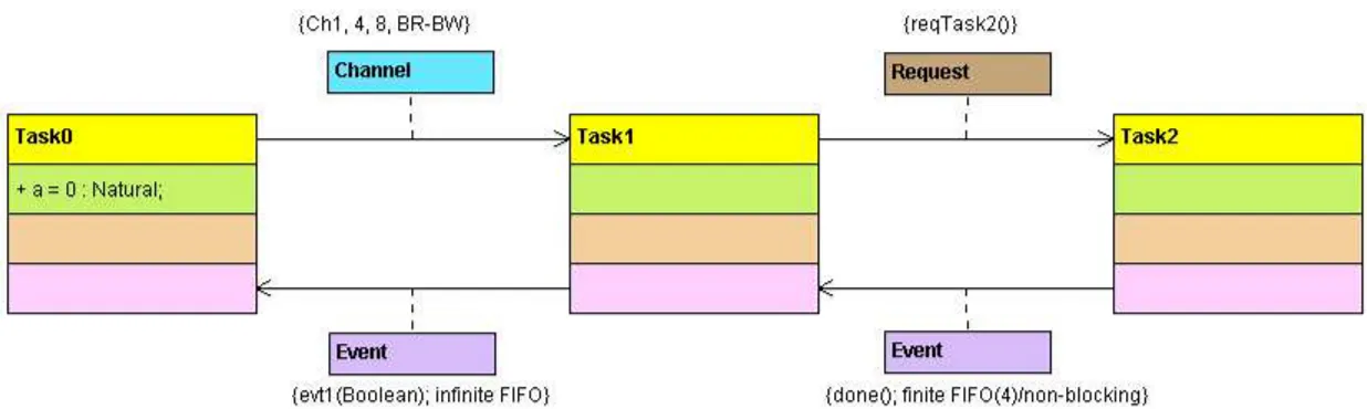
4 Architecture and Application Modeling 49 4.1 UML the Unified Modeling Language: Models, Metamodels and Profiles 49 4.2 Application Modeling . . . 514.2.1 Application Structure Task Model . . . 51
4.2.2 Application Structure Component Model . . . 54
4.2.3 Application Behavior Model . . . 58
4.3 Architecture Modeling . . . 63
4.3.1 Architecture Resources Model . . . 63
4.3.2 Architecture Communication Interaction Model: “Communi-cation Patterns” . . . 67
4.4 Summary . . . 71
5 System Mapping Modeling 73 5.1 Mapping motivational example . . . 73
5.2 Shared Resources Modeling . . . 76
5.2.1 Resource definition . . . 77
5.2.2 Shared Resources’ Control: The “Virtual Node” . . . 78
5.2.3 Virtual Node vs Real Implementation . . . 80
5.3 Execution Allocation . . . 82
5.4 Storage Allocation . . . 83
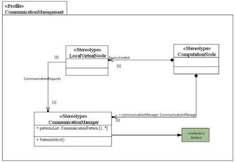
5.5 Communication Management Modeling . . . 84
5.6 Mapping Validation . . . 85
CONTENTS
5.8 System Mapping Example . . . 89
5.9 Summary . . . 90
6 Models Simulation for Performance Analysis 93 6.1 Introduction . . . 93
6.2 State of the Art on SystemC . . . 94
6.2.1 System’s Design in SystemC . . . 95
6.2.2 Concurrency . . . 96
6.2.3 SystemC Simulation Kernel . . . 96
6.3 A SystemC Simulation Environment for DIPLODOCUS models . . . 98
6.3.1 DIPLODOCUS SystemC simulator concurrency . . . 99
6.3.2 System’s Timing: From DIPLODOCUS commands to physi-cal time . . . 100
6.3.3 Simulation’s Timing semantics and Interruptions Support . . . 104
6.3.4 The simulator in a nutshell . . . 105
6.4 Performance Monitoring . . . 110
6.4.1 Simulator Default monitoring . . . 112
6.4.2 Personalized Performance Metrics: Observers . . . 113
6.5 Summary . . . 114
III Approach’s Validation
115
7 Use Case Study: SoC Modeling for LTE Base Station 117 7.1 LTE: The Long Term Evolution Standard . . . 1177.1.1 Overall LTE Network Architecture . . . 118
7.1.2 Key Technologies of the 3GPP LTE Air Interface . . . 120
7.1.3 LTE Radio Link Protocol Layers . . . 121
7.2 Use Case Modeling . . . 123
7.2.1 Scope of the use case . . . 124
7.2.2 Application Model: LTE Physical Layer . . . 126
7.2.3 Architecture Model: Freescale MSC8156 Multi-Core DSP . . 127
7.2.4 Mapping Model . . . 130
7.3 Use case analysis . . . 133
7.3.1 Application Execution Performance Metrics . . . 134
7.3.2 Comparison of simulation results to real implementation results 135 7.4 Use case study conclusion . . . 137
8 Conclusions and Perspectives 139
A Résumé en français 151
A.1 Introduction . . . 151
A.1.1 Contributions de la thèse . . . 153
A.1.2 Plan de la thèse . . . 154
A.2 Complexité de la conception des systèmes sur puces . . . 156
A.3 Flot de conception d’un système sur puce . . . 158
A.3.1 Les étapes d’un flot de conception . . . 160
A.3.2 Conception au niveau système . . . 160
A.3.3 Prototypage virtuel . . . 162
A.3.4 Prototypage . . . 162
A.4 Contributions de la thèse . . . 163
A.4.1 Contrôle des ressources partagées: Le ”virtual node” . . . 163
A.4.2 Modèle d’interaction des noeuds d’architecture Interaction communication: ”les motifs de communication” . . . 166
A.4.3 Comparaison des résultats de simulation aux résultats réels d’implémentation . . . 168
List of Figures
2.1 Evolution of data versus voice transfer in US cellular networks . . . . 20
2.2 Evolution of cellular network’s throughput and protocols . . . 21
2.3 The Freescale DSP based SoC for LTE physical layer . . . 23
2.4 SoC Design Flow . . . 27
3.1 The Extended DIPLODOCUS methodology . . . 40
4.1 DIPLODOCUS Application Modeling profile . . . 51
4.2 Application Structure Task metamodel . . . 54
4.3 A simple application modeled by DIPLODOCUS Task Model with TTool 54 4.4 The Component Modeling metamodel . . . 57
4.5 The Component Modeling metamodel . . . 59
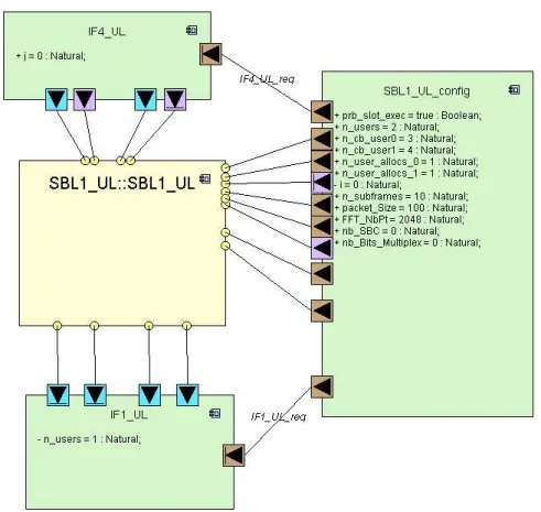
4.6 The uplink physical layer of the LTE standard modeled using the pro-posed DIPLODOCUS model . . . 60
4.7 Application behavior metamodel . . . 62
4.8 A simple application behavior modeled using the DIPLODOCUS Ap-plication Behavior profile . . . 63
4.9 Architecture Modeling Profile . . . 64
4.10 Architecture Resources Metamodel . . . 66
4.11 An example of a DIPLODOCUS Architecture Model with TTool . . . 67
4.12 An example of simple Communication Pattern . . . 68
4.13 Communication Pattern metamodel . . . 71
5.1 Mapping Demonstrative example . . . 74
5.2 DIPLODOCUS Mapping Modeling profile . . . 76
5.3 A simple hierarchical scheduling example . . . 79
5.4 A simple dynamic scheduling example . . . 80
5.5 DIPLODOCUS Shared Resources Modeling profile . . . 81
5.6 DIPLODOCUS Execution Mapping profile . . . 83
5.7 DIPLODOCUS Storage Mapping profile . . . 85
5.8 DIPLODOCUS Communication Management Modeling profile . . . 86
5.10 System Mapping Example . . . 91
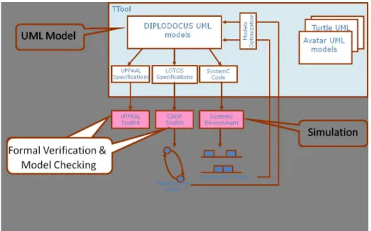
6.1 Simulation and formal verification with TTool . . . 98
6.2 Calculation of the number of CPU’s cycles needed to execute a DIPLODOCUS “Exec” command . . . 103
6.3 Task Timing behavior . . . 106
6.4 The DIPLODOCUS Flow - Performance estimation and optimization of system models . . . 107
6.5 An excerpt of the SystemC generated for the Application model . . . 108
6.6 An excerpt of the SystemC code generated for the Architecture model 109 6.7 An excerpt of the SystemC generated for the Mapping model . . . 111
6.8 A VCD diagram of the task T1 execution and the evolution of its state in time . . . 113
7.1 LTE Network . . . 119
7.2 LTE Data Flow through the protocol layers . . . 123
7.3 LTE Physical Layer uplink flow . . . 124
7.4 LTE Generic Frame Structure . . . 125
7.5 The higher level of hierarchy in the LTE uplink physical layer model . 126 7.6 Application Structure Task metamodel . . . 128
7.7 An excerpt of the Behavior of a Physical Resource Block (PRB) Task 129 7.8 An example of a DIPLODOCUS Architecture Model with TTool . . . 129
7.9 An example of a priority based access policy for a computation virtual node . . . 131
7.10 Possible States of a task during its execution . . . 132
7.11 Virtual nodes and their access policies . . . 132
7.12 Excerpt of the Execution allocation of LTE uplink to the computation Virtual nodes . . . 133
7.13 LTE uplink physical layer flow for one user . . . 134
7.14 An excerpt of the execution of the PRB0 task . . . 135
7.15 LTE uplink Tasks computation complexity . . . 136
7.16 LTE Tasks execution performance metrics . . . 136
7.17 Simulated MCPS compared to measured MCPS . . . 137
A.1 Notre thèse dans le contexte de la méthodologie DIPLODOCUS . . . 153
A.2 Le DSP multi-coeur Freescale pour la couche physique du protocole LTE157 A.3 Flot de conception pour les systèmes sur puces . . . 161
A.4 Un simple exemple d’ordonnacement hiérarchique . . . 165
A.5 Un simple exemple d’ordonnacement dynamique . . . 166
A.6 Un simple exemple de motif de communication . . . 167
Chapter 1
Introduction
1.1 Thesis Context
The development and evolution of modern System-on-Chip "SoC" can be character-ized by its main target: miniaturization. Highly advanced features are associated with targets in terms of performance, energy consumption, security, viability, and many other. All of these features are mainly enabled by the impressive technical and techno-logical advances in both fields of semi-conductors and software engineering.
On the other side, the development cycle becomes shorter to challenge the compe-tition. Furthermore, to differentiate their product, industrials are integrating more and more functionalities and hence increasing the design complexity. For instance, a mod-ern mobile phone, in addition to the telecommunication standard, integrates a camera, a music player, a GPS, Internet browsing tools and many other applications.
System’s higher complexity [40], [53] forced designer to re-evaluate their design methodologies. Initially, design was performed at transistor level, and then it evolved to the logic gate level and later to register transfer level (RTL). Tools developed at the RTL level enabled designers to verify the system’s behavior. However, the increasingly growing complexity and heterogeneity of electronics embedded system push designer to raise the level of design abstraction to the system level that target the co-design of the entire SoC, rather than just individual components.
In this context, many methodologies and approaches [28] are targeting system level design. These methodologies provide designers with means to model the system and then analyze and optimize it. System analysis could target various domains such as functional verification, performance estimation, and power estimation. In addition, higher levels of abstractions enable fast system evaluations and performance analysis. However, the first challenge remains to choose the appropriate level of abstraction that preserves the accuracy of results.
interdepen-dent applications at low cost (area, power) to the end user, the number of resources must be minimized while increasing their utilization by sharing them between mul-tiple applications. Such shared resources have a strong impact on SoC performance because of the contention they typically induce. Indeed, end-to-end performance of a given application is the sum of the time needed to execute that application with the total contention delay of all involved shared resources. Shared resources contentions, communication delays and many other factors play a role in the overall system per-formances. Thus, identifying the main factors that influence the system’s performance and how to model them constitute another challenge in performance analysis.
Once the performance metrics (such as latency, throughput, resource utilization, etc.) identified and modeled, the designer can perform multiple system’s evaluation (through simulation or other analysis mechanisms) to explore various combinations of architecture (number of computation units, communication topology, etc.) and application (number of tasks, parallelism between tasks, etc.). Ideally, s/he wants to verify if the system’s performances satisfy the design requirement. Thus, rapidly extracting the performance metric needed to perform the design analysis is a primor-dial step in the system design. The system designer, can then choose among different possible solution the one that is most adapted. Hence, a third challenge that needs to be considered is how to analyze the extracted performance metrics of the modeled system to verify its satisfaction to design requirements.
Thesis Objective. The objective of this Thesis work is to provide the system designer with means (on the methodology and tools levels) to estimate system’s performances and evaluate rapidly and very early the design decisions in the SoC design flow. Specification of the abstraction level and methods for the analysis of abstract models is the key for a successful system level design methodology. Modeling at a high level of abstraction eases the system-level design decisions making process, as the designer does not need to have detailed expertise on lower level software, hardware, and design tools.
This thesis work is done in the framework of the DIPLODOCUS methodology developed at Telecom ParisTech. DIPLODOCUS defines a UML profile [76] targeting design space exploration at a high level of abstraction. The following section describes briefly the contributions of our thesis.
1.2 Thesis Contributions
Towards the above mentioned objective, following are the proposed contributions of this thesis, classified into three levels:
meta-modeling concepts) of meta-modeling concepts to take in consideration:
– the shared resources impact on system’s overall performances, by defin-ing the “virtual node” concept for scheduldefin-ing and shared resources access control.
– the orthogonalization of computation and communication concerns by defining the Communication Pattern concept for modeling the interaction between architecture elements.
• Contribution on the Simulation Level: A SystemC simulator was written to simulate the UML models. Simulation is done at a high level of abstraction and runs faster than real time execution.
• Contribution on the Experiment Level: The proposed approach was applied on an industrial case study. A muli-core Freescale DSP platform for LTE base stations was modeled and validated by comparison to the real platform to esti-mate its accuracy and speed
1.3 Thesis Layout
This thesis report is divided into six chapters as follows:
• Chapter 2 provides an overview of the System-on-Chip design domain and the increasing design complexity. It describes as well the typical SoC design flow, that starts from the client specification and through various refinements results in a functional SoC product. The flow covers both application and architecture parallel development and their integration and validation.
• Chapter 3 presents the system level design domain concepts and objectives and provides a survey of existing methodology. In a second part, this chapter de-scribes the DIPLODOCUS methodology on which our research work is based and compares it and the extensions added during this thesis with the state of the art.
• Chapter 4 illustrates the DIPLODOCUS modeling of the application and the architecture and presents the Communication patterns for communication mod-eling. It provides the UML meta-models for the different modeling concepts. • Chapter 5 presents the mapping process proposed to execute the application on
top of the architecture. It defines the concept of virtual node for shared resources access control and how it could be used to develop useful access policies for SoCs design. The mapping includes as well an allocation step that defines how
the architecture resources (computation, communication and storage resources) are allocated to application artifacts. An example is used to illustrate the different steps of the mapping process.
• Chapter 6 describes the simulation environment developed and used to simulate the DIPLODOCUS models and to extract performance metrics that will help designers to make early design decisions.
• In Chapter 7 the methodology developed is used to model an industrial system, the LTE uplink physical layer that will execute on a multi-core platform. The simulation results are compared with the real implementation.
Part I
PhD Domain Overview and State of
the Art
Chapter 2
System-on-Chip Design and
Application Domains
This PhD work is done with the aim to develop a high level modeling methodology for System-on-Chip (SoC) performance estimation. This chapter provides a global view of the domain of the research work. It shows the complexity of the design of a SoC, by using the example of the LTE (Long Term Evolution) standard for cellular networks and an example of a real chipset designed for its implementation. Then, the second part discuss the SoC design flow and steps and how this PhD work fits into it.
2.1 Introduction
Systems-on-Chips are omnipresent in the modern daily life and environment, like Telecommunication systems and devices, automotive, avionics, multimedia devices, etc. This evolution comes in pair with an evolution in the embedded hardware. In fact, the computation power is growing rapidly following the Moore’s law. More sophisti-cated and complex applications are introducing new functionalities and trying to cover new markets, while increasing the complexity of the embedded hardware. Hence, The design complexity of modern embedded systems is exploding due to the market de-mand for more, increasingly complex features, and shorter time-to-market.
The objective of this chapter is two-fold. The first objective is to illustrate the com-plexity of modern SoCs through an example on a wireless telecommunication stan-dard (LTE), and its implementation in an industrial context. The second objective is to present the conventional SoC Design flow and situate the topic of this PhD work.
This chapter is organized as follow. Section 2.2 presents the LTE wireless com-munication protocol, with special focus on the throughput increase introduced in this protocol and the inherent complexity needed to support this feature. Then section2.3
characteristics. The complexity of design of such systems, and the design challenges that it imposes are presented in section 2.4. The section2.5 describes the main steps of the conventional SoC design flow that, through multiple iterations and refinement, permits the creation of a SoC from the initial client specifications.
2.2 LTE Standard for Mobile Communication: Higher
Complexity for better quality of services
In the last two decades, the world wide cellular network utilization has evolved from voice oriented to data oriented networks. In fact, Figure2.1compares the rapid growth in wireless data traffic compared to voice traffic across multiple operators in the United States [83]. This evolution is basically a structural one that affected the network in-frastructure and came with new standards for supporting more quality of services.
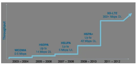
Figure 2.1: Evolution of data versus voice transfer in US cellular networks The mobile communication systems have evolved from 1st generation, which are analog cellular systems and limited to voice transfer, through 2nd generation-known as digital narrowband that introduced data transfer to cellular networks, to 3rd generation (3G), with higher bandwidth radio interface and throughput. The latest commercial-ized wireless network technologies, called High Speed Packet Access (HSPA)[32], is currently deployed around the world. The evolution of 3G networks is under imple-mentation and will be ready to be deployed in the following years. The standardization work of the Long Term Evolution (LTE) [33], started from 2004, is close to comple-tion. LTE provides higher data rate compared to previous standards, with the peak of more than 300 Megabits per second in downlink and 50 Megabits per second in uplink. Besides, it provides lower user costs, better spectrum efficiency, smaller latency and many other advanced features. Figure2.2shows the evolution, over the last decade, of throughput of the cellular network standards [10]. The throughput is increasing from less than one Mbps in 2003 to more than 300 Mbps as expected by 2012. This dramatic
growth of throughput is mainly driven by the increasing demand for Internet connec-tivity on mobile devices. Mobile Users are now expecting to have the same quality of service (high throughput, stable connection, low latency, etc.) while accessing to their requested multimedia contents, from anywhere and even when they are on the move.
Figure 2.2: Evolution of cellular network’s throughput and protocols
The evolution of cellular networks is becoming a cyclic process: Higher through-put enables sophisticated mobile applications, and the later are requesting even more higher throughput. The user’s experience and satisfaction depends on the quality of services provided by the operator and by the quality of the mobile device s/he is using. Hence the network infrastructure and the design of mobile devices become more com-plex . So, The higher throughput comes with an increasing comcom-plexity of the devices (software and hardware) that will implement the standards. In order to achieve the re-quired performances, complex heterogeneous architectures are used, including many processors, many hardware accelerated parts, specific communication infrastructure and various input/output interfaces.
Another factor of complexity is that LTE itself was meant as an evolution and not a revolution of the existing standards. It will co-exist and inter-work with the 3G system. Thus, the LTE network base stations will be even more complex as they will support as well the previous standards. In fact, multi-standard platforms are currently developed by the principal platform companies (like Alcatel [12], Ericson [31], Huawei [44] and others).
This increase in complexity is common between the different embedded application domains, and the SoC implementation of all these applications share the following trends:
1. New features and value added services, lead to the increase of processing and communication requirements.
2. The standards are introduced more rapidly and become more sophisticated. This calls for high flexibility of the SoC implementation to meet the resulting time-in-market severe constraints.
3. The reuse of developed components is increased, to shorten time to market and reduce production cost.
4. For mobile devices and sensors, reduced size and power efficiency become pre-vailing cost factor and product differentiation.
2.3 A SoC example for LTE implementation
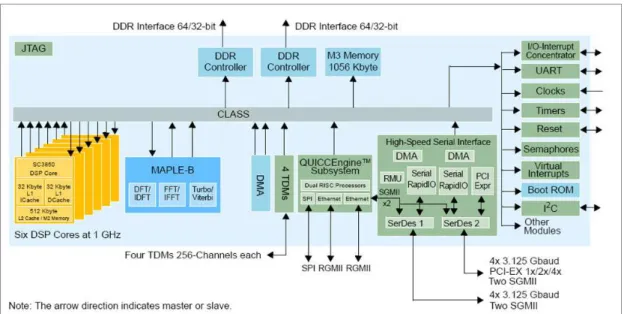
Industrial solutions for the embedded application reflect the application complexity. Furthermore, heterogeneous multi-core SoC platforms are generally believed to meet the above mentioned conflicting performance, flexibility and energy efficiency require-ments of demanding embedded applications. The heterogeneity of SoC implementa-tions is driven by the heterogeneity of the embedded applicaimplementa-tions, where each part of the application has an inherent suitable implementation technology. Figure2.3depicts the architecture of a DSP SoC, MSC8156 [73], produced by Freescale Semiconductor [72], that targets among others the wireless broadband domain. This DSP is currently used in industrial implementations of the base stations of the LTE standard developped by companies like Alcatel. This SoC has been used to test and validate the methodol-ogy developed in this thesis. More details on its modeling and performance estimation of the implementation of the LTE physical layer are provided in Chapter 7.
The MSC8156 DSP delivers a high level of performance and integration. It com-bines together six DSP cores, each running at up to 1 GHz, a hardware accelerator (maple-B) that supports hardware acceleration for Turbo [55] and Viterbi [81] channel decoding, in addition to DFT/iDFT and FFT/iFFT algorithms (these algorithms re-quire high computation performances). It includes as well a high-performance internal RISC-based (QUICC Engine) subsystem that supports multiple networking protocols to guarantee reliable data transport over packet networks.
The MSC8156 embeds an on-chip memory (M3) of 1 MByte, and two interfaces for off-chip DDR memories. In addition, each DSP core has its own internal L1 and L2 caches. It supports a variety of advanced, high-speed interface types, including two “RapidIO” interfaces, two Gigabit Ethernet interfaces for network communications, a PCI Express controller, two DDR controllers for high-speed industry standard memory interface. The set of all these integrated components are connected through a Chip-Level Arbitration and Switching Fabric (the CLASS), that ensures non-blocking, fully pipelined and low latency communication scenarios. The system is doted as well by two DMA blocks to transfer the large quantity of processed data. To have an idea on the data transfer performed and the complexity of the data processing, recall that this
Figure 2.3: The Freescale DSP based SoC for LTE physical layer
system is used to implement a part of the LTE standard, and it guarantees throughput of more than 100 Mbps.
2.4 System on Chip Design Complexity
A System on Chip (SoC), like the one presented in the previous section, integrates soft-ware and hardsoft-ware jointly and is specifically designed to provide given functionalities to the surrounding environment [40], [53]. The system must be able to continuously react to stimuli in the desired way, i.e., within bounds on timing, power consumption, and cost. As introduced in the previous sections, such systems are highly complex and heterogeneous. In fact, the complexity of system design is dramatically increasing in three dimensions:
1. Heterogeneity and complexity of the hardware architecture: New design tech-nologies and higher integration density result in increasing the computational power of modern SoCs which enables sophisticated functions to be embedded in ever-smaller devices. A modern SoC may include general purpose processors (GPP), Application-Specific Instruction-set Processors (ASIP), different com-munication topologies, complex memory hierarchy, different Input/Output de-vices ... The Freescale DSP MSC8156 presented in section2.3is a good example of such architecture.
power of SoCs grows, more advanced functionalities are introduced. Software is taking the lion’s share of the implementation budgets and cost. For instance, in a cell phone, more than one million lines of code are the standard today [69]. In contrast with traditional software systems where the abstraction process leaves out all the physical aspects of the systems as only the functional aspects of the code matter, the embedded software is at least loosely coupled to the hardware architecture which limits the code reuse when the system specifications evolve. Furthermore, heterogeneous applications share the same hardware architecture: a cell phone device must be able to handle simultaneous voice and data calls, while also handling complex imaging tasks like image or video capture. This heterogeneity increases the complexity of resource sharing and design optimiza-tion.
3. Integration complexity: During the integration phase, software and hardware components are integrated to create the SoC. As these components are usually developed by different teams and sometimes in different countries (and/or by different companies), this phase is of extreme complexity [41]. Verification and re-engineering work done during this phase is time consuming and expensive.
2.5 System on Chip design flow
A System-on-Chip design is an iterative process, that aims the implementation of a product based on the client specifications. A System-on-Chip design flow is a suc-cession of refinements and optimizations steps to accomplish the system design. Each step of the flow consists of modeling and/or implementation, verification and integra-tion of hardware and software. The ideal design starts with a high level descripintegra-tion of the functionality and the architecture. The designer is expecting for the following from SoC design flow:
1. Reuse of the existing code and models developed for previous products to fasten the design cycle. One should note that usually new products are an evolution of existing product and rarely a revolution. Hence, design reuse can lead for considerable cost reducing factor.
2. Identify design decisions early in the design flow. Late design changes are ex-pensive and time consuming, thus finding the bottlenecks and estimating the system’s performances at early stages reduce the design’s cost and increase the productivity.
3. Ensure a functioning product, that satisfies the client requirements. Thus, the adopted verification and validation process should be correct and accurate in order to lead to a correct product.
The design specification at each design step must cover the specification of the functionality and the architecture of the system. Currently, there is no standard lan-guage or format for design specification. In addition to specification, each level of the SoC design flow should define verification and validation methodologies to verify the satisfaction of the design with the requirements.
Specification Languages
Many programming languages and modeling paradigms are used to specify the func-tionality of a SoC. While embedded software is usually written in C, the funcfunc-tionality could be described with a different paradigm: it could be directly written in C or spec-ified using synchronous languages such as Esterel [21], Lustre/SCADE [39], Signal [19], from which some tools can automatically generate C code and formally verify the system. More recently UML is proposed to enable the specification of very com-plex applications by providing a large set of language constructs. In addition UML has the advantage of being implementation independent [58][56].
For hardware design, system level design relates to any level of abstraction that is above the register-transfer-level (RTL). Transaction-level modeling (TLM) [37], be-havioral, algorithmic, and functional modeling are terms often used to indicate higher levels of abstraction in hardware design. Due to its popularity and efficiency, the C programming language and its derived languages are gaining in the market. Many ap-proaches and tools propose synthesis of C code into RTL code; Catapult C (Mentor) [38], Handel-C [26] are well known examples of these approaches and tools. In ad-dition new approaches are using UML for modeling of SoC hardware and software. Simulation code, formal verification specification or synthesis code may be gener-ated afterwards from the high level UML models; Gaspard2 [18][56], Koski [47], and DIPLODOCUS methodology described and extended in this thesis [14][45] and many other approaches has adopted this approach.
Ideally a specification language spans many abstraction levels so that it can be used throughout the design process.
Verification and Validation
Verification and Validation is a phase of system development, that is performed at the different levels of abstraction and where software and hardware are analyzed to verify that they satisfy the desired properties. The most common techniques for design validation and verification are simulation and formal verification. While simulation permits the evaluation of large and complex systems, formal verification is a process for checking whether a system satisfies a given property under all possible inputs, and is applied to safety-critical subsystems to ensure correctness.
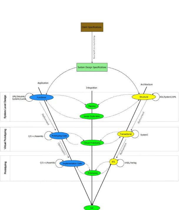
2.5.1 SoC Design flow steps
Figure2.4 shows a typical SoC design flow. It starts from the client specification and through various refinements its result is a SoC product, ideally ready for the market. From the client specifications the experimented designers will gather design require-ments and define a first draft of the system specification. Then, through three main steps, the design will evolve from the client specification to a system level model than through virtual prototyping a more thorough analysis is done to finally give the final product with the prototyping phase. In each step software and hardware are ideally developed/modeled in parallel and an integration step permits to evaluate the system design progress and satisfaction to design requirements.
2.5.2 System Level Design
Approaches to raise the level of abstraction in SoC design are called “System-Level Design Methodologies”. Their objective is to help designers to take and validate de-sign decisions at early stages of system dede-sign. They permit dede-signers to model, sim-ulate, explore, verify and refine a system design. Some frameworks further provide a design flow by integrating a set of refinements to transform a system-level model to an implementation. Ptolemy [23], Artemis [66], CoFluent Studio [29], Metropolis [16], Koski [47], Design Space Explorer (DSX) [57], Platform Architect (CoWare) [77], SoC Designer (ARM - Carbon Design Systems) [25] and many others are well known examples of system-level design frameworks and tools.
Most of these approaches adopt a clear separation between the application and the architecture modeling. Thus, a mapping phase is needed to bind both models and to define the execution of the application on the architecture. After Mapping, the system is evaluated to test if it meets to design requirements. This phase is called: Design Space Exploration. Its objective is to find an optimal model that fits the requirement. Design choices like how many cores are needed or how much on-chip and off-chip memories are required are ideally taken at this stage.
In figure2.4, the system level design is the first step after the specification of the system based on the client specifications. Application and architecture are modeled first, then their mapping and the design space exploration phase. Based on the system validation and test during this exploration, the designer can modify her/his models.
2.5.3 Virtual prototyping
Virtual prototyping is the second main step in the process of product development. Its main objective is to validate a design before committing to making a physical proto-type. In fact, the design process for SoC-based platforms suffers from productivity issues due to the effort needed for verifying and validating the system. System
fication is typically carried out at an intermediate to lower level of abstraction: pro-totype software implementations with transaction-level or register-transfer-level hard-ware models. It is very expensive and time consuming to create these prototype system models, and thus it is also expensive to revise system architecture decisions. Further-more, because of higher system integration (and thus complexity), the design risk and the associated verification cost are higher. Rapid virtual prototyping of the system can verify the system in a real environment and identify potential implementation bottle-necks, which could not be easily identified in the previous step. A working virtual prototype can demonstrate to clients the feasibility and show possible technology evo-lutions, thus significantly shortening the time to market.
Transaction level model (TLM [37]) is one of the most well-known models that can serve as a virtual prototype. This step comes just after the system level design step. The code is more mature and the designer can make more accurate analysis. Even though, the simulation time is clearly higher than at system level design.
2.5.4 Prototyping
Prototyping corresponds to the integration of the optimized software during the pre-vious design step on the final product hardware or on FPGA based platform that cor-responds to actual hardware. Final verification are executed on the design and new validation tests prepare for the final step of the SoC design corresponding to the cre-ation of hardware masks that will be the base of the SoC silicon production. At this step of the design flow, it is very expensive to make design changes. Hence, the vast majority of tools and approaches are trying to validate the system at earlier steps.
2.6 Summary
The approach to cope with the increasing design complexity of SoCs is to raise the level of abstraction, moving the development process from lines-of-code to coarser-grained architectural elements. Modeling accurately the functionality and the candidate system architectures at an early stage is becoming essential for a successful system design. In addition, higher levels of abstractions enable fast system evaluations and performance analysis. However, the challenge remains to choose the appropriate level of abstraction that preserves the accuracy of results.
The system Level Design is a promising domain, that is used widely nowadays. Many approaches are trying to take benefit from the system level to take early design decisions. This PhD work fits into the system level design domain and has as a main objective to estimate SoC’s performance at early design stages. The next chapter will review the state of the art of system level design and presents the contributions of this thesis.
Chapter 3
System Level Design: Models,
Methodologies and Trends
The previous chapter showed the design complexity of modern Systems on a Chip (SoC) and the design flow used for their design, validation and implementation. De-sign at system level proved to be a good solution to reduce complexity and early per-formance analysis based on abstract models has already been demonstrated to increase design efficiency [50; 67;82]. System-level design frameworks are commonly based on models meant to describe functions to be implemented by a set of candidate hard-ware architectures.
The objective of this thesis is to develop a methodology for system level modeling and early performance analysis of SoCs. Our approach is based on the DIPLODOCUS UML profile. The main contributions of this thesis are a set of extensions for DIPLODOCUS to model shared resources and ensure orthogonalization of the com-munication and computation. A SystemC based simulator is developed as well to simu-late and estimate models performances. After describing the concepts and objectives of system level design, this chapter will position the proposed approach (DIPLODOCUS plus the extensions) wrt to existing approaches.
3.1 Introduction
3.2 System Level Design: Concepts and Objectives
“System Level Design”refers to large set of design methodologies [36] that target the design of the entire SoC, rather than just individual components. Such methodologies provide designers with means to model the system (its functionality and architecture), and then analyze and optimize it. It is worth noting that the system level design is a large domain and various industrial and academic approaches exist to tackle differentaspects of design (functional verification, performance estimation, power estimation, etc.). However all these approaches share some basic concepts: all of them target modeling at a high level of abstraction, they adopt to some extent the separation (or-thogonalization) of concerns to increase the modularity and re-usability and to reduce analysis time. Furthermore, all of them are equipped with a design space exploration process to analyze and to optimize the system level models
3.2.1 Modeling and abstraction
System’s complexity and heterogeneity are influencing the development of system level design methodologies. As shown in section2.4 of the previous chapter, the in-creasing complexity can be identified on the application level, the platform level, as well as on their integration. The ever increasing number of transistors on a die helps by increasing the computation power and memory space. However, more advanced methodologies on system level (application and platform) are required to better take advantage of the added silicon. The design shift from super-scalar mono-processors to multi-cores platforms (in the telecommunication, multimedia, networking and other application domains) is confirming this trend for enhancing the utilization of the plat-form. To cope with this increasing complexity a system level design approach proceeds by modeling and abstraction of the system in order to analyze it.
A model by definition, is a “ representation of some phenomenon of the real world made in order to facilitate an understanding of its workings. A model is a simplified and generalized version of real events, from which the incidental detail, or ’noise’ has been removed” [71].
An Abstraction(s) enables designers to understand (analyze) complex domains of concern, like programs, software systems, and their application domains, which contain a plethora of detail. It is a process of separating essentials from details, and focusing on the former while ignoring, "abstracting away", the latter. Creating abstract models help designer to better understand the system under design by reducing com-plexity. Abstraction can be seen as the process of hiding aspects of the design in order to increase the ability of the designer to only consider those which help to develop a design at that particular stage. Examples of abstraction could be a set of transistors being abstracted as logic gates, a set of bus transactions being reduced to an IP in-terface, or a set of processor instructions (add, divide ...) being represented by their computation complexity. For instance the DIPLODOCUS profile made a choice of data abstraction to focus more on the control behavior of the system and to identify the system execution to better estimate its performance.
Higher levels of abstraction allow designer to make early design decisions, as the changes performed at these levels affect dramatically the overall design. However, the designer has less insight into how precisely and accurately the changes brought about this change. Thus, a system level methodology is the first step in the design flow and
is always followed by more optimizations and refinements of systems models.
3.2.2 Separation of concerns
The abstraction done at the system level design allows for a designer to think of tra-ditional software and hardware aspects of the design separately. The Algorithmic part is decoupled from the architectural elements which implement them. The Y chart in-troduced in [50;51] is widely adopted by system level methodologies. It consists of modeling separately the application (what the system should do) and the architecture (how it can do it), and then integrating both during a mapping phase. For instance, a signal processing algorithm (FFT, Viterbi, ...) itself is well defined functionally, and some Matlab/Simulink models may exist to simulate this functionality. However, the architecture that will implement this algorithm may be DSP-based or a dedicated hard-ware block. In the mapping phase the architectural element (the DSP or the Hardhard-ware block) is allocated to the application. As the application and architecture concerns are separated, models are reusable and so a designer can easily evaluate candidate archi-tectures using the same application model. This separation also permits the exploration of mapping of two different applications on a given architecture during first stages of projects.
Furthermore, Keutzer et al. [50] extended the separation of concerns principal to include the separation of computation and communication concerns. In other words, the “how” the system computes should be separate from the “how” system’s compo-nents interact.
The following subsection will describe the Design Space Exploration used for an-alyzing and optimizing the system level models.
3.2.3 Design Space Exploration
”Design Space Exploration”(DSE) is the process of looking at a variety of designs and using the results of simulation, verification, or other analysis methods to make decisions regarding which design should be selected. These modifications that can be made to a design to optimize its performance, and to observe potential design issues that may have been overlooked during specification. The DSE process is done prior to the development of implementation prototypes. It relies on the system level of abstraction, where the models’ modification cost is smaller than on a low level of abstraction. In fact, abstract models can be quickly changed in terms of structure, behavior, design parameters and components to test new system configurations. These higher-level abstractions enable a faster exploration of a larger design-space.
In general, the exploration process is a multi-objective one [48]. The list of sup-ported objectives includes the SoC size, power consumption, execution speed, through-put and many others. After a first analysis step the designer can optimize the system
model to satisfy one (or more) objective. To do so, s/he can modify the applica-tion models (algorithmic decisions, task partiapplica-tioning), the architecture models (number of computation resources, memory hierarchy, communication infrastructure), and the mapping decisions (tasks’ memory map, execution allocation of the computation archi-tecture to the tasks, the scheduling decisions and choices). The consequent complexity and size of the design space prevent an exhaustive search to find the optimal solution satisfying all of the objectives. Hence, establishing a priority of the design objectives is required, and the design exploration process tries to find one possible (not necessarily the optimal) solution for the exploration problem with the specified priorities.
In the system level design literature, two explorations methods are widely used: analytical and simulation-based methods. In general, analytical methods are used to prune the vast design space rapidly but with very coarse models while simulation-based methods explore in more details a part of the design space. Simulation models are well suited to identifying characteristics of a dynamic system that are hardly predictable. They can be used to explore the task scheduling (especially with interruption), com-munication scheduling and dynamic input models. Analytical methods fit well for application with limited dynamic behavior. Some approaches combine both methods to exploit their best properties. In both types of methods, a major aspect of the design space exploration process of a system level design methodology is the time required to define the design objective and the time required to evaluate (explore) the system model to validate its satisfaction to the objective.
3.3 System Level Specification Languages
In a system level design methodology, the choice of a suitable specification language is primordial. Ideally, the language should support different abstraction levels and capture the concurrency and timing of a SoC (the so called expressiveness of the lan-guage). Furthermore, it should be supported by easy-to-use tools (compilers, modeling tools, ...).
Various specification languages exists and often more than one language are used in a SoC system design process. For instance, the embedded software is mainly writ-ten in C and assembly, while VHDL[6] and Verilog[1] are largely used to describe the hardware specification at register transfer level (prototyping phase as described in the section2.5of the previous chapter). At the system level of abstraction the objective is more to first model the system (software and hardware), then in a next step to generate the code of it. The trend is to use the same language for the application and the archi-tecture as the designer can easily master one language and take profit of already known languages (such as C/C++, UML ...). The following the next subsections will present some of the most used specification languages for software and hardware modeling.
3.3.1 C/C++ based design languages
C/C++ are popular for software development, and are familiar to an important part of designers and engineers. Thus, many initiatives want to take advantage of this popu-larity to introduce new system design languages with ideally a fast learning curve for new designers/engineers. In this scope, the two major initiatives are SystemC that is based on C++, and SpecC that is based on C. In both cases, the language is enriched with concurrency and timing constructs to better model SoCs.
SystemC is a language proposed by the Open SystemC Initiative (OSCI) [43], and had a large industrial and academic support. The language is standardized by the IEEE standard 1666-2005 [4]. SystemC is used to describe the hierarchical structure and the behavior of complex embedded systems. It can be used to describe the system at differ-ent levels of abstraction. Using SystemC, a system can be described at functional level, architectural level, and implementation level. SystemC is a C++ library that provides the constructs needed to express hardware timing, concurrency, and reactive behavior that are missing in standard C++. The OSCI simulation kernel (free download) is used to simulate the SystemC models. Being an extension of C++, SystemC profits from all the legacy compilers and tools developed for this language.
SpecC [34; 59] is a superset of the ANSI C programming language. It is devel-oped at the University of California, Irvine, to address system level design. The SpecC language and the underlying methodology were created by Rainer Domer and Daniel Gajski. Similarly to SystemC, it enriches the C language with a system design library addressing the timing and concurrency aspects. SpecC defines different levels of ab-stractions to take in consideration the timing representation of the computation and the communication.
3.3.2 Synchronous Languages
Synchronous languages [20] target the design of reactive systems. These systems are interacting permanently with their environment. Their execution is a set of atomic “instantaneous” reactions to inputs of the environment. A synchronous model is deter-ministic, in contrast with the non-determinism of the classical sequential programming and concurrent formalism such as Petri-nets. Thus, Synchronous languages are used for development of safety-critical systems in avionics and industrial control. The syn-chrony assumption of the synchronous models makes them particularly interesting for hardware design. In fact, it is identical with the zero-delay model of electronic circuits. Therefore, most synchronous languages provide automatic translation/generation in VHDL. Esterel[21] and Lustre/SCADE [39] are well known synchronous languages.
Lustre/SCADE targets the dataflow programming. It is formally defined and con-tinuously developed since 1984. A LUSTRE program is called a node. It is declared with two sets of parameters: inputs and outputs, and the body of the node defines
the functional relationship between inputs and outputs. Variables in Lustre are data streams. Calculations and data exchange between nodes are instantaneous. In 1993, Lustre became a part of the industrial environment SCADE developed nowadays by Esterel Technologies. One of Lustre/SCADE success stories is its adoption for mod-eling safety critical parts of the A380 Airbus plane (the world passengers largest air plane).
3.3.3 UML: Unified Modeling Language
The Unified Modeling Language (UML) [76], initially targeted complex software modeling and was for example used for modeling banking systems. UML 2.0 (the actual version of the UML standard) is a graphical specification language for object modeling that captures the abstract system specifications. The main feature of UML is its genericity, thus it is not limited to a specific domain. In fact the UML profiling mechanism permits the extension of UML for modeling a specific domain. UML can be considered as an emerging specification language for embedded systems, and many UML profiles (some of these profiles are described in section3.5.2) target the ded systems design specification. An important step for the UML adoption in embed-ded systems design was the standardization of the Marte UML profile targeting em-bedded and real time systems. Unfortunately, UML is still lacking full-interoperability between tools. This limits the exchange of models between different companies or teams and reduces the opportunity to build libraries of UML models as it is the case in C++, Matlab and VHDL
3.3.4 Matlab/Simulink
Matlab is a mathematical environment used for algorithm development. Control The-ory and digital signal processing are two main domains where Matlab is used to model the underlined algorithms. These later can be simulated using the Simulink tool that provides flexible simulation capabilities and a wide range of tools for visualizing re-sults. Matlab/Simulink is largely used in industry and a large components legacy is available. Thus, building new models is made simpler due to increased re-use. Both continues time and discrete time models can be simulated using Matlab. In addition, it is sometimes possible to generate C implementation of Matlab models. However, this code does not take into consideration complex architectures with complex communi-cation and memories infrastructure. The Matlab simulation is mainly useful to study the modeled system at the algorithmic level.
3.3.5 Discussion
All the above presented specification languages target system level design. However, some of them are textual while the others are graphic, some target reactive safety crit-ical systems while others target signal processing systems, some rely on a formal se-mantics while others are simulation based. A system level design methodology should be generic and ideally target different design domains. Thus it could relies on one or more specification languages. UML is generic and extensible (through the profiling mechanism) to target different domains. In fact, it is common nowadays, to find ap-proaches [18; 47; 82] where the system’s specification is done in UML and where the performance analysis step uses a model translation/transformation into SystemC or other simulation languages. This later approach is adopted for the work presented in this thesis. It is possible as well to generate different simulation/analysis codes from UML such as Matlab, and SCADE
3.4 Survey of some Existing System Level Design
Methodologies
The System Level design domain is a large and promoting domain. Several Industrial and academic approaches are proposed and developed. Examples of such design frameworks and languages are Ptolemy II [23], Metropolis [17] , Koski [47] and MESH [22]. This section describes, briefly, some of these system level design methodologies. The objective is not to provide an exhaustive list but rather to introduce the relevant ones with this thesis work.
Metropolis [17] is based on a meta-model that supports multiple types of model of computation and that can be extended to support others. It specifies applications and architectures separately and the association (mapping) between them. The basic modeling elements in Metropolis are processes, ports, media, quantity manager and state media. Processes represent the system’s functionality and communicate through ports. The ports are interfaced using media, and the quantity manager define the scheduling scenarios. The Metropolis environment provides techniques and tools for formal verification and for simulation of developed models.
Ptolemy II [23] is a meta-modeling framework, implemented in JAVA, for het-erogeneous and hierarchical designs of embedded systems. It focuses on simulation and the interaction between different models of computation. It uses tokens as the underlying communication mechanism. Directors regulate how actors execute in the design and how tokens are used to communicate between them. This mechanism allows different models of computation to be constructed within Ptolemy. Hierarchical
composition is used to handle heterogeneity. Each level in a hierarchy has a director that organizes the bring of the actors at that level. Ptolemy does not focus on function-architecture separation and mapping.
Koski design flow [47] provides a single framework for modeling of applications, automatic architectural design space exploration, automatic synthesis, programming, and prototyping of selected MPSoCs. Koski’s design flow starts with the capturing, in UML, of requirements for an application and architecture, including design constraints, such as the overall maximum cost. The environment is doted with a UML interface that handles the transformation of application and architecture models to an abstracted model for fast architecture exploration. Particularly, the application model is transformed to an abstract process network model. In addition, the UML interface can back-annotate the UML design with performance information obtained from lower-level simulations. The design space exploration process is composed of a static (analytical) and a dynamic (simulation based) steps. Once an “optimal” system is defined, the last step of the Koski framework is to automatically generate the low-level code (software C code and hardware VHDL code).
MESH [22] stands for Modeling Environment for Software and Hardware. It separates the design into three parts: the software layer (corresponding to functional model), the hardware resource layer (corresponding to the architecture model) and the scheduling layer between them (corresponding to mapping). Each layer provides a set of services to the layer next above. The scheduling layer allocate an execution resource to a software thread. Software threads are annotated with time budgets for the corresponding hardware elements. This timing cost is extracted beforehand by estimation or profiling.
Gaspard2 [18] is an environment providing designers with the following means: a formalism for the description of embedded systems at a high abstraction level (based on the Marte UML profile), a methodology covering all system design steps, and a tool-set that supports the entire design activity. The model of computation adopted by Gaspard 2 offers a very suitable way to express and manage the potential parallelism in a system. Different automatic refinements steps from the high level of abstraction to-wards the lower levels are defined: for simulation at different levels with SystemC, for hardware synthesis with VHDL and for formal validation with synchronous languages. Syndex [52] is a system-level computer Aided Design (CAD) software that enables to quickly explore the solution space to extract an efficient solution and generate a real time distributed executive without deadlock for multi-components architectures. It is based on the AAA, Algorithm Architecture Adequation, methodology that aims to find the best matching between an algorithm and an architecture, while satisfying design
constraints. AAA is based on graphical models that model both the potential paral-lelism of the algorithm and the available paralparal-lelism in the architecture components. The implementation consists in distributing and scheduling the algorithm data flow graph on the architecture multicomponent while satisfying the real-time constraints. This is formalized in terms of graphic transformations. Heuristics are used to optimize real time performances and resource allocation for embedded real-time applications on the SOC.
At an industrial level, there are as well many approaches for system level design and virtual prototyping. Hereafter a brief description of two of these industrial ap-proaches: Panama [75] and CoFluent [29].
Panama[75] is an in-house Freescale development, with the main objective of enabling early analysis when some information is not yet available; namely lack of software applications and stable hardware component definitions. It targets to reach the desired accuracy while maintaining a good simulation speed. The application is specified using the TML (Task Modeling Language) language that contains abstract constructs to express an application flow with regards to its use of hardware resources. The architecture is specified in SystemC at the cycle accurate level. After a first analysis using the TML model, the modeling could be enriched using simulation traces to increase the accuracy. It is worth noting that Panama does not describe the application and architecture in an orthogonal fashion. In fact the task modeling language includes details of the underlying architecture which mixes the architecture and application models.
Cofluent tools [29] are based on the MCSE [64] methodology developed by the reasearch team of professor Jean-Paul Calvez. It provides a graphical description for the application and the architecture that resembles to UML and recentely a UML profile for CoFluent has been defined [30]. An internal tool enables the automatic generation of SystemC code from the graphical description in order to analyze the behavior. The MCSE methodology covers the design flow from requirements collection up to the prototyping.
Discussion
System Level Design methodologies represent a large umbrella of tools and ap-proaches. The set of previously described approaches are few examples of existing well-known approaches. In fact, even back in 2006, D. Densmore et al [28] counted a 90 different academic and industrial system level design tool and/or methodology. However, these tools are sharing some common trends and similarities:
architecture concerns, and the separation of communication and computation is becoming more popular
• Usage of the same specification language to specify the architecture and the application. Usually this language should rely on a clear definition (meta-model) of the modeled concepts. For instance Metropolis relies on a formal meta-model and Gaspard2 and Koski rely on well defined UML profiles. UML is getting the hype in this domain, especially that its semantic is generic and independent from any particular implementation
• Increasing interest in formal verification techniques integration to design flows • Code Generation for simulation and analysis from the high level models.
Sys-temC is largely the most preferred language due to its standardization and adop-tion in industry.
3.5 DIPLODOCUS and Extensions: Yet Another
Sys-tem Level Design Methodology for Early Design
Analysis
The objective of this PhD work is to develop a methodology for performance esti-mation of complex SoCs at a high level of abstraction and in early design stages; ultimately, when software and hardware are not yet defined. Thorough architecture performance exploration cannot be performed with cycle and bit accurate system mod-els, because they are too detailed and thus very expensive to be built and require an equally advanced software implementation. A general solution is to use abstract sys-tem models for both application and architecture. The challenge remains to preserve the accuracy of the performed estimations. Raising the level of abstraction will reduce the time needed for developing models, thus reducing the effort before the first perfor-mance estimations. The proposed approach extends the DIPLODOCUS UML profile to model shared resources and communication architecture interactions. Performance analysis and design exploration process are performed by using the SystemC based simulator developed to simulate the SystemC code generated from the UML models.
3.5.1 Modeling Approach
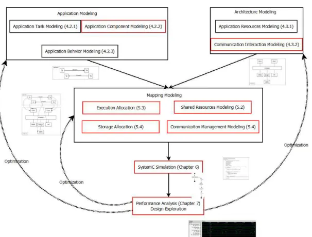
Figure A.1 depicts our approach, the red boxes represent our contribution to the DIPLODOCUS methodology. The numbers between brackets represent the section or chapter that will describe the specific part of the approach. The “Application Mod-eling” package specifies how the functionality of the system is captured. It provides