HAL Id: pastel-00000745
https://pastel.archives-ouvertes.fr/pastel-00000745
Submitted on 21 Jul 2010HAL is a multi-disciplinary open access archive for the deposit and dissemination of sci-entific research documents, whether they are pub-lished or not. The documents may come from teaching and research institutions in France or abroad, or from public or private research centers.
L’archive ouverte pluridisciplinaire HAL, est destinée au dépôt et à la diffusion de documents scientifiques de niveau recherche, publiés ou non, émanant des établissements d’enseignement et de recherche français ou étrangers, des laboratoires publics ou privés.
un outil pour les diagnostics plasma et une source
innovante pour les applications.
Sven Fritzler
To cite this version:
Sven Fritzler. Sources de particules avec des lasers de haute intensité: un outil pour les diagnostics plasma et une source innovante pour les applications.. Physique [physics]. Ecole Polytechnique X, 2003. Français. �pastel-00000745�
Contents
1 Introduction 1
1.1 Scientific Context of Particle Production with High Intensity Lasers . . 1
1.2 Objectives of Thesis . . . 3
1.3 Thesis Outline . . . 3
Part I : Theoretical Basics 5 2 Particle Acceleration Mechanisms 7 2.1 Elementary Definitions . . . 7
2.1.1 Laser Parameters . . . 7
2.1.2 Plasma Parameters . . . 10
2.2 Underdense Plasma . . . 14
2.2.1 Nonlinear Optics Phenomena . . . 15
2.2.2 Plasma Wave Growth Rates . . . 20
2.2.3 Wavebreaking – Electron Beam Generation . . . 22
2.2.4 Coulomb Explosion – Ion Beam Generation . . . 26
2.3 Overdense Plasma . . . 28
2.3.1 ~v × ~B Heating – Electron Beam Generation . . . . 28
2.3.2 Electrostatic Field – Proton Beam Generation . . . 30
Part II : Neutrons as a Diagnostic for Plasma Ion Temperature 35 3 Methodological Basics 37 3.1 Implications of Fusion Neutron Generation . . . 37
3.2 Previous Work and Motivation . . . 38
3.3 D(d, n)3He Reaction . . . . 39
3.4 Summary and Discussion . . . 44
4 Experimental Set-up 47 4.1 VULCAN Laser System . . . 47
4.2 Diagnostics . . . 49
4.2.1 Gas Jet and Optical Diagnostics . . . 50
4.2.2 Deuteron Detectors . . . 51
4.2.3 Neutron Detectors . . . 53
5 Experimental Results 59 5.1 Gas Jet Interaction . . . 59
5.1.1 Neutron Energies . . . 59
5.1.2 Plasma Ion Temperature . . . 61
5.1.3 Neutron Yield . . . 62
5.2 Beam Target Interaction . . . 63
5.2.1 Deuteron Measurements . . . 63
5.2.2 Secondary CD2 Target . . . 65
6 Discussion 69 Part III : Electron Beam Generation in the FLWF Regime 71 7 Experimental Layout 73 7.1 Previous Experiments and Motivation . . . 73
7.2 Experimental Parameters . . . 75
7.2.1 “Salle Jaune” Laser and Optical Diagnostic . . . 75
7.2.2 Initial Plasma Electron Density . . . 76
7.3 Electron Beam Diagnostics . . . 77
7.3.1 Electron Spectrometer . . . 77
7.3.2 Integrating Current Transformer . . . 79 ii
7.3.3 Radiochromic Film and Copper Stack . . . 79
7.3.4 Nuclear Activation Diagnostic . . . 81
7.3.5 Emittance Diagnostics . . . 83
8 Experimental Results and Simulations 89 8.1 Electron Spectra and Yield . . . 89
8.1.1 Experimental Result . . . 89
8.1.2 Comparison with 3D PIC Simulation . . . 90
8.2 Transmitted Laser Beam . . . 93
8.3 Electron Angular Divergence . . . 94
8.3.1 Measurement with RCF and Copper Stack . . . 94
8.3.2 Activation Measurement . . . 95
8.4 Emittance . . . 95
8.4.1 Measurement with Pepper-Pot Diagnostic . . . 96
8.4.2 Comparison with Numerical Modelling . . . 96
8.5 Bunch Length Calculations . . . 97
9 Forced Laser Wakefield Regime 99 10 Applications and Conclusions 101 10.1 Electron Source . . . 101
10.1.1 Injector for Conventional Accelerators . . . 101
10.1.2 Ultra Fast Radiation Chemistry . . . 103
10.2 Feasibility as X-Ray Source . . . 107
10.2.1 Channelling Radiation . . . 107
10.2.2 Thomson Scattering . . . 110
Part IV : Proton Beam Generation with Foil Targets 112 11 Motivation and Experimental Layout 115 11.1 Previous Work and Motivation . . . 115
11.2 Experimental Layout . . . 116
11.2.1 Laser Parameters and Targets . . . 117
11.2.2 Proton Detector . . . 117 iii
12.1.1 Experimental Results and Discussion . . . 121 12.1.2 Numerical Modelling . . . 123 12.2 Irradiation under 45◦ . . . 125 12.2.1 6 µm Plastic Foil . . . 125 12.2.2 13 µm Plastic Foil . . . 127 13 Applications 131 13.1 Positron Emission Tomography . . . 131
13.1.1 Principle and Requirements . . . 131
13.1.2 Benefits using High Repetition Rate Laser Systems . . . 132
13.1.3 Expected Activities . . . 132
13.2 Proton Beams as Radiographic Source . . . 134
13.2.1 Interest in Probing Laser Plasma Interactions . . . 134
13.2.2 Experiment and Results . . . 134
14 Conclusions and Perspectives 139 14.1 Conclusions . . . 139
14.1.1 Neutrons as a Diagnostic for Plasma Ion Temperature . . . 139
14.1.2 Electron Beam Generation in the FLWF Regime . . . 140
14.1.3 Proton Beam Generation with Foil Targets . . . 141
14.2 Perspectives . . . 142
Annex 144 A List of Publications 145 A.1 Articles in Refereed Journals . . . 145
A.2 Articles in Non-Refereed Journals . . . 147
Bibliography 149
List of Figures
Part I : Theoretical Basics 5
2.1 Laser ponderomotive force . . . 9
2.2 Principle of Forward Raman Scattering . . . 17
2.3 Transverse laser focusing . . . 18
2.4 Accelerating field as a function of ambient electron temperature . . . . 24
2.5 Plasma wave and associated electric field . . . 24
2.6 Accelerating and focusing segments in electron plasma waves . . . 26
2.7 Schematic electron spectra for different electron acceleration processes . 29 2.8 Proton cut-off energy from plasma expansion into vacuum . . . 34
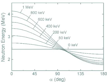
Part II : Neutrons as a Diagnostic for Plasma Ion Temperature 35 3.1 Geometry for D(d, n)3He reaction in laboratory system . . . . 40
3.2 Neutron energy as function of angular emission for D(d, n)3He . . . . . 41
3.3 Laboratory differential cross section for D(d, n)3He . . . . 41
3.4 Cross section for D(d, n)3He reaction in laboratory system . . . . 43
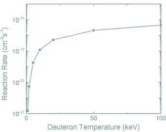
3.5 Reaction rates for D(d, n)3He fusion of Maxwellian distributions . . . . 44
4.1 Schematic of the VULCAN Nd:Glass laser chain . . . 48
4.2 Experimental set-up . . . 50
4.3 Forward Raman Scattering at 5.5 × 10⁻¹⁹ cm−3 . . . . 51
4.4 Function ϕ0(ρx) for indium foils . . . . 55
4.5 Set-up of indium activation targets . . . 56
5.1 Neutron TOF signal . . . 59
5.2 Measured neutron energy for different angles of emission . . . 60 v
5.5 Coulomb explosion deuteron spectrum . . . 63
5.6 Angular distribution of deuteron emission . . . 64
5.7 Set-up of secondary CD2 target . . . 65
5.8 Neutron spectra at θ of 67◦ . . . . 66
5.9 Angular distribution of neutron emission . . . 67
Part III : Electron Beam Generation in the FLWF Regime 71 7.1 Schematic of the “salle jaune” Ti:Sa laser chain . . . 75
7.2 Experimental set-up for electron acceleration experiment . . . 77
7.3 Radiochromic film and copper stack . . . 80
7.4 Schematic of activation measurement . . . 81
7.5 Schematic of measurement with pepper-pot . . . 84
7.6 Definition of geometry of pepper-pot mask . . . 85
7.7 Sensitometric response of MD55 . . . 86
8.1 Experimental electron energy spectra . . . 89
8.2 Numerical modelling of electron density and laser intensity in plasma . 91 8.3 Numerical modelling of electron density and associated electric fields . 91 8.4 Calculated electron energy distribution . . . 92
8.5 Transmitted laser spectra . . . 93
8.6 FWHM of the angular distribution of electron beam . . . 94
8.7 Nuclear activation angular distribution measurement . . . 95
8.8 Spread of divergent angle versus pinhole position for pepper-pot mask . 96 8.9 Normalized vertical emittance as a function of electron energy . . . 97
8.10 Calculated longitudinal electron phase space . . . 98
10.1 Possible injector configuration based on FLWF scheme . . . 101
10.2 Experimental bunch charge spectrum . . . 102 vi
10.3 Experimental set-up for Femtolysis experiment . . . 104
10.4 Electron spectrum for Femtolysis experiment . . . 105
10.5 Absorption of probe laser beam . . . 106
10.6 Principle of channelling . . . 107
10.7 Possible channelling radiation spectrum . . . 108
10.8 Integrated channelling photon yield . . . 109
10.9 Schematic of Thomson X scattering . . . 110
10.10Calculated Thomson X spectrum . . . 110
Part IV : Proton Beam Generation with Foil Targets 112 11.1 CR-39 arrangement . . . 118
11.2 Energy resolution with aluminum filters . . . 119
11.3 Opening cone determination with aluminium filters . . . 119
12.1 Proton spectra for irradiation at normal incidence . . . 121
12.2 FWHM of proton beam for irradiation at normal incidence . . . 122
12.3 Calculated proton energy . . . 123
12.4 Numerical Modelling of proton phase space . . . 124
12.5 Proton spectra of two beams for 6 µm plastic target . . . 125
12.6 FWHM of two proton beams for 6 µm plastic target . . . 126
12.7 Traces on CR-39 of two distinct proton beams . . . 126
12.8 Dependence of proton energy on laser intensity for 6 µm plastic target . 127 12.9 Proton spectra of two beams for 13 µm plastic target . . . 128
12.10FWHM of two proton beams for 13 µm plastic target . . . 128
12.11Dependence of proton energy on laser intensity for 13 µm plastic target 129 13.1 Principle of Positron Emission Tomography . . . 132
13.2 Experimental set-up for proton imaging . . . 135
13.3 Example of proton imaging . . . 136
List of Tables
Part I : Theoretical Basics 5
2.1 Ionization energies and intensity thresholds for SBI model . . . 11
Part II : Neutrons as a Diagnostic for Plasma Ion Temperature 35
3.1 Neutron parameters and energy discrimination . . . 38 4.1 VULCAN laser parameters for described experiment . . . 49 5.1 Maxwellian deuteron distribution temperatures . . . 61
Part III : Electron Beam Generation in the FLWF Regime 71
7.1 “Salle jaune” laser parameters for electron acceleration experiment . . . 76 7.2 Nuclear reactions used . . . 81
Part IV : Proton Beam Generation with Foil Targets 112
13.1 Calculated activities for medical isotope production . . . 133
Chapter 1
Introduction
1.1
Scientific Context of Particle Production with
High Intensity Lasers
Elementary particles like electrons, protons and neutrons are since their discovery of great interest and relevance in various domains and as their intrinsic parameters are well understood, their implementation is even today of great actuality. Here, e.g., an energetic proton beam bombarding matter resulted in the discovery of the top quark, a constituent of hadrons [1], whereas the collision of two energetic electron and positron beams proved experimentally the existence of the gluon, which describes in quantum chromodynamics the transmission of the strong force between two quarks [2]. Scattering of neutrons by an ordered magnetic structure commonly reveals information on the creation of magnons, hence, visualizes quantized spin waves [3]. Even though these experiments can be tremendously copious, they are all based on electron, proton and neutron sources.
Implementing such particle sources their basic parameters like luminosity, bunch length, source size, as well as quality in terms of angular divergence and emittance are of great importance. A higher luminosity, i.e., particle flux per unit area and time can obviously be preferential for the number of experimental events. Shorter particle bunches permit to investigate studies with higher temporal resolution, and in case they are used for radiography, a small, point-like source could be desirable to enhance the resolution.
Today, the most efficient electron sources are guns of photo-injectors, where lasers with energies of some tens of µJ and pulse durations of some ps irradiate cathodes. This liberates electrons, which are subsequently preaccelerated in radio frequency cavities operating with electric fields of around 50 MV/m. So far, this can yield bunch charges of 10 nC with durations of typically 5 ps. Implementing additional magnetic chicanes can shorten these electron bunches to about 1 ps [4]. Interestingly, the laser focal waist on these cathodes is typically of the order of 100 µm, thus, the electron source size can be approximated to be of the same order of magnitude. It is clear that these benefits are due to the small focal spot as well as short pulse length of the lasers used for these conventional accelerators.
However, these lasers are not intended to accelerate electrons to high energies even though it is known that laser electric fields can be well beyond those of radio frequency cavities. With the advent of the Chirped Pulse Amplification (CPA) [5], high power, sub-ps laser pulses became available. Focusing such lasers down to focal waists of some
µm and intensities beyond 1018 W/cm2, intrinsic electric fields of the order of TV/m
can be obtained. These laser electric fields, though, are transverse oscillating fields which are not suitable for acceleration of free particles. Nevertheless, at such high intensities these lasers can create quasi-instantaneously plasmas on targets they are focused onto, i.e., they generate a medium consistent of free ions as well as electrons. Inside this plasma, the transverse electric laser fields can be turned into longitudinal plasma electron oscillations, known as plasma waves, which are indeed suitable for electron acceleration. Additionally, due to the high laser intensity, strong quasi-static electric fields can be induced, which can accelerate ions [6].
These principles were recently shown in numerous “proof of principle” experiments. Here, the interaction of high-intensity lasers with a plasma resulted in the generation of energetic electron [7] and ion [8] beams, which was found to be due to the induced electric [9] and magnetic fields [10] during this interaction, which can be beyond some TV/m and several hundred MG, respectively. Hence, in contrast to photo-injectors, high-intensity lasers combine the generation and acceleration of particles.
Importantly, this approach has several unique factors : (i) The particle bunches originate from small laser focal volumes; (ii) they are evoked by sub-ps laser pulses which suggest short particle bunch lengths of the same order of magnitude; (iii) due to the induced high electric field gradients the acceleration distance to high energies can be significantly cut down.
So far, much of these experimentation has involved large-scale, “single-shot” lasers. However, due to their inherently large costs and low repetition rates it is unlikely that such laser systems will favor applications of these unique particle sources. Thus, the extension of these studies to smaller, but higher repetition rate lasers, maintaining the same focused intensities is required. This will elucidate whether or not this approach to simultaneously generate and accelerate particles is indeed valuable for applications. However, not only the pure characterization of these particle sources is of interest. As the schematic indicates
Laser + Plasma → Interaction → Particles
Energy, Density, Yield,
Pulse Length Scaling Length Energy,
Focal Waist Angular Divergence
1.2. Objectives of Thesis 3
the initial laser and plasma parameters are known and as the resulting particles can be precisely measured the determination of laser produced particle sources permits to draw conclusions on the interaction itself. Hence, it can be seen as a diagnostic for laser plasma interactions.
In this context particularly neutron generation by the fusion of low energy ions can reveal ion dynamics, yields and heating processes in plasmas. Hence, with this method it is possible to experimentally characterize even those ions, which are not sufficiently energetic to escape the plasma.
1.2
Objectives of Thesis
This PhD dissertation is an experimental study on particle generation with high-intensity lasers. Within the scope of this work several experiments were performed in France at Laboratoire d’Optique Appliqu´ee and in England at Rutherford Appleton Laboratory, whose aims were to :
1. Generate electrons, protons as well as neutrons by laser plasma interactions in continuation of previously conducted work;
2. Characterize these particle sources by means of energy, yield, emission profile, angular divergence and emittance;
3. Decipher the mechanisms occurring during these interactions;
4. Propose and possibly realize applications in comparison to conventional particle sources.
1.3
Thesis Outline
This manuscript is divided into four parts, whereas the first is dedicated to theoret-ical basics of particle generation and acceleration mechanisms during relativistic laser plasma interactions. The additional three parts cover experimental studies on neutron, electron as well as proton generation :
• Part I will present the scientific context of this thesis, i.e., basic laser and plasma
characteristics will be introduced as well as physical processes of interest during the interaction of a relativistic high-intensity laser with an underdense / overdense plasma.
For the underdense regime the generation of relativistic electron plasma waves will be summarized, which can result in the self-modulated laser wakefield scheme in an energetic electron beam. Furthermore, ion acceleration by the known Coulomb
explosion will be described. For the overdense regime the laser plasma interaction will be briefly considered in the context of proton beam generation.
• Part II will introduce methodological basics of neutron generation by D(d, n)3He
reactions since this can reveal information about ion kinetics and possible ion heating mechanisms in plasmas.
Subsequently the set-up for this experiment, pursued in the underdense regime, will be described in detail. The experimental results will be discussed for the gas jet interaction as well as for the beam target model since it was deduced that plasma ions are heated during this interaction to fusion temperatures of about 1 keV.
• Part III describes the generation of an electron beam with an energy of up to
200 MeV in a new regime termed “Forced Laser Wakefield.” Here, the presented experimental results were for the first time fully explained and even extended by the numerical modelling of this interaction in terms of energy, yield, angular divergence, emittance as well as bunch length of this electron beam.
Applications of this electron beam for accelerator physics and the generation of secondary X-rays via the channelling effect and Thomson scattering will be assessed theoretically. The utilization of such an electron beam for current quests in ultra fast radiation chemistry will be demonstrated experimentally.
• Part IV will delineate a 10 MeV proton beam generation using foil targets and
a 10 Hz laser. Again the kinematic simulation of this experiment is in agreement with the experimental results by means of yield and angular divergence.
Calculating the production of medical isotopes with this proton beam indicated that this approach can indeed be competitive with contemporary accelerators, providing kHz repetition rates of the laser used. An example that such a proton beam can probe laser plasma interactions will be presented, which demonstrates its superiority in terms of spatial and temporal resolution compared to conven-tional sources.
Finally, a summary of the observed results will be given and suggestions will be made, how these studies can and should be extended in the very near future. Some interesting, ambitious and particularly important perspectives will conclude this manuscript.
Part I
Chapter 2
Particle Acceleration Mechanisms
By way of introduction, a brief review on essential laser and plasma parameters will be given. Their interaction will subsequently be presented for overdense and underdense plasmas, as well as for this manuscript essential particle generation and acceleration mechanisms.
2.1
Elementary Definitions
In the following, basic laser characteristics like intensity and ponderomotive force will be considered. As for high-intensity lasers the potential of their electric field exceeds by far the ionization threshold of matter, plasmas can be instantaneously created by the pedestal of these laser pulses. Therefore, relevant plasma generation mechanisms will be revealed and basic plasma characteristics subsequently discussed.
2.1.1
Laser Parameters
Lasers emit monochromatic and coherent electromagnetic radiation, whose propa-gation is described by the Maxwell equations [11]. Today, they do cover a wide range of wavelengths as well as applications [12], which is why in the following only short pulse lasers with a pulse length below 1 ps will be regarded, since in the manuscript presented here, the experiments were performed on such laser systems.
2.1.1.1 Laser Intensity
The electric as well as magnetic field of these lasers are assumed to have a Gaussian profile, which can be decoupled spatially and temporally. Since these fields are perpen-dicular to each other, their vector product gives both the direction and the quantity of energy flow. Its mean value is the intensity, I, which is in a focal spot given by
I(r, t) = ILexp à −2 µ r w0 ¶2! exp à −4 ln 2 µ t τ0 ¶2! , (2.1) 7
where τ0 is the full width at half maximum (FWHM) of the pulse length and w0 the
waist of the focal spot, which is the laser beam diameter at e−1 of its amplitude.
Integrating I(r, t) over space and time, reveals the maximum laser amplitude, IL, to
be IL' 0.6 EL w2 0τ0 , (2.2)
where EL is the laser pulse energy. Clearly, focusing a 1 J laser with a 30 fs FWHM
pulse length onto a 18 µm spot containing 50% of the laser energy results in an intensity of about 3 × 10¹⁸ W/cm2.
Importantly, the envelope and therefore the intensity of such a focused laser pulse changes with distance along the laser propagation axis, z, as
w(z) = w0 s 1 + µ z zR ¶2 , (2.3)
where zR is the Rayleigh length, which is given as a function of the laser wavelength,
λL, by zR= π w2 0 λL . (2.4)
This Rayleigh length is thus the distance over which the laser intensity decreases by a factor of 2 relative to the intensity in the focal spot. Assuming that a laser with a wavelength of 820 nm is focused down to a focal waist of 4 µm, zR is about 61 µm.
Relativistic Laser Intensity
Today, intensities well in excess of 1018 W/cm2 are commonly available at many
laboratories worldwide. Since the associated electric field of such a laser pulse is given in (V/m) by
E = 2.7 × 10¹²qI
18, (2.5)
where I18 is the laser intensity in (1018 W/cm2), their impact on matter has obviously
to be considered. Therefore, it is convenient to define a normalized vector potential,
a0, which corresponds to the normalized, classical, velocity of free electrons, v⊥/c,
oscillating in a linearly polarized electric laser field by
a0 = v⊥/c = v u u t 1 2π2² 0 e2 m2 ec5 λ2 LIL = 0.85 λL(µm) q I18. (2.6)
2.1. Elementary Definitions 9
Here, −e and me are the charge and the mass of an electron, ²0 the permittivity of free
space and c the speed of light in vacuum. Consequently, for a0 > 1 electrons will be
relativistic and the component of the Lorentz force induced by the laser, ~v⊥× ~B, has to
be taken into account since electrons can acquire an additional longitudinal movement from this force.
2.1.1.2 Ponderomotive Force
As free electrons quiver in the electric field of such laser pulses they are subjected to a variation of the laser intensity. This can be expressed in the non-relativistic case with the fluid equation of motion within an electromagnetic field by
∂~v ∂t + (~v · ∇) ~v = − e me ³ ~ E + ~v × ~B´, (2.7)
where ~v is the electron velocity vector. This equation can be developed to second order to the ponderomotive force, ~Fp, given as
~ Fp = − e2 4meω2L ∇(E2) = − e2 2c²0meωL2 ∇I, (2.8)
by time averaging the electric laser field, when ωLdescribes the laser period [13]. As it is
indicated in Fig. 2.1 electrons are pushed by this force along the intensity gradient, i.e., away from the focal spot of the laser, where the intensity is the greatest. Furthermore, as mentioned above, the inclusion of the Lorentz force distorts the oscillation of the electrons and can drive electrons along the direction of propagation of the laser. An analytical solution for the relativistic case is given in [14].
Figure 2.1: Scheme of the laser ponderomotive force. Due to the transverse oscillation of electrons in the electric laser field they get accelerated perpendicularly towards the laser axis. Additionally, they can get pushed along the laser propagation axis for sufficiently short laser pulses.
Self-explanatory, it is possible to ascertain the laser a ponderomotive potential, Φp, which is Φp = e 2E2 4meωL2 . (2.9)
For a laser intensity beyond 1017 W/cm2 this ponderomotive potential exceeds 6 keV,
which is by far stronger than the binding energy between an electron and a nucleus. It is thus Φp that can induce the generation of a plasma in a target such a laser is focused
onto. It is clear that not the maximum laser intensity is required for this ionization but that the pedestal of the laser pulse is sufficient.
2.1.2
Plasma Parameters
A plasma is an electrically conducting collection of free, positively and negatively charged particles as well as neutral atoms and molecules. The permanent and unsorted motion of these particles defines a temperature of this many-body system and corre-sponds to their kinetic energy, which can be beyond the ionization energy of matter. 2.1.2.1 Plasma Creation
At laser intensities beyond 1017 W/cm2 atomic electrons can be rapidly ionized
by the sole influence of the electric field of the laser. Hence, a plasma is created. Many theoretical approaches tried to predict this plasma creation, whereas one of the simplest was derived by Keldysh, which used perturbation theory of a simple atom [15]. However, it makes no allowance for the internal structure of the atom and is thus only really applicable for hydrogen and helium, but it can be approximated for high as well as low laser intensities. Here, the Keldysh parameter, γK, which is defined as
the square root of the ratio of the ionization potential, εi, to twice the ponderomotive
potential distinguishes between different ionization regimes
γK =
s
εi
2 Φp
. (2.10)
Multi Photon Ionization
The case γK > 1 is considered as the multi photon ionization regime, which is
the process where the atom passes through the absorption of single photons through multiple short lived virtual states to gain sufficient energy to become ionized. This is the dominant process when the laser intensity is relatively low and the laser frequency is high.
2.1. Elementary Definitions 11
Tunnel Ionization
For γK < 1, or tunnel ionization regime, it becomes energetically preferential for
atomic electrons to exist unbound but they are prevented from leaving the atom by the Coulomb barrier. This barrier is reduced by the laser electromagnetic field so that it is energetically preferable for atoms to exist ionized [16]. Since the electronic wave function can penetrate this barrier it is possible that electrons can quantum mechanically tunnel through the Coulomb barrier.
Barrier Suppression Ionization
For the extreme case γK ¿ 1 the atomic Coulomb barrier is suppressed, liberating
electrons [17]. An estimate of the required laser intensity, IBSI, can be obtained by
equating the ionization potential for a given ionization state to the potential experi-enced by an electron for a given laser intensity. This potential is a combination of the Coulomb field, which is corrected for screening effects of the inner electrons and the maximum electric field of the laser. IBSI is then given in (W/cm2) as
IBSI = π2²3 0c 2 e6 ε4 i Z2 = 4 × 10⁹ ε4i(eV ) Z2 , (2.11)
where Z is the ionization state of the ionized atom. Table 2.1 gives some ionization energies and intensity thresholds according to this BSI model. In [18] it was shown that this ionization process is completely induced before the main laser pulse arrives. Solid State
As mentioned earlier, γK is only really applicable for simple atoms. Obviously, this
is not the case for solid states where complex atoms are bound into a crystal lattice,
Table 2.1: Ionization energies [22] and resulting intensity thresholds according to the BSI model for deuterium and helium.
Gas species Potential threshold IBSI
(eV) (W/cm2)
D 13.5 1.3 × 10¹⁴
He+ 24.6 1.4 × 10¹⁴
which changes the ionization potential. However, it was shown in numerical [19] as well as analytical approaches [20] that these above described ionization mechanisms are still the dominant processes for plasma generation in solid states. This agrees with experimental results, where the creation of a plasma in aluminium foils was found to occur for intensities beyond 1012 W/cm2 [21].
In summary, it has been shown that plasmas are instantaneously created on gaseous and solid targets by the pedestal of commonly available laser pulses with intensities beyond 1018 W/cm2. It is noted that the contrast ratio of such laser impulsions is
crucial for the subsequent laser plasma interaction. This contrast ratio is defined as the ratio of the laser intensity at its maximum over the intensity in the ns time scale before the main impulsion. Obviously, a laser with a low contrast ratio is capable to significantly heat the target before the main laser pulse arrives. This can result in the generation of a preplasma and compounds the numerical modelling of the subsequent interaction.
2.1.2.2 Plasma Characteristics
A plasma is characterized by several macroscopic values such as the electron and ion temperature, Te and Ti, the electron density, ne, and the mean charge state, hZi.
In case plasma electrons move coherently, electron plasma waves are created, which do have the following characteristics :
Plasma Frequency
If plasma electrons are displaced from their equilibrium position they will experience a restoring force from the electrostatic field created by this charge separation. For small oscillations this leads to the so-called plasma frequency, ωp, given in (rad/s) by
the expression ωp = s nee2 ²0me (2.12) = 5.64 × 10⁴√n e.
Assuming a plasma electron density of 2 × 1019 cm−3, this plasma period is 25 fs. In
contrast, plasma ions with mass mi and charge Z oscillate with the period
ωpi =
s
Z me mi
ωp. (2.13)
Due to the significant mass difference between electrons and ions these waves oscillate much slower than electron plasma waves. For an electron density of 1 × 1019 cm−3
2.1. Elementary Definitions 13
in a helium plasma, ωpi−1 is around 300 fs. Since this is about ten times below the corresponding electron plasma period, this ion oscillation is neglected during their first cycles.
Dispersion Relation
For an electromagnetic wave, (ω, ~k), propagating through a plasma the dispersion relation is given as
ω2 = ω2
p+ c2k2, (2.14)
where k is the wavenumber. As electron plasma waves are electrostatic waves, which can be described by an oscillating electron density modulation, δne, as
δne = δn0exp[−i( ~kp· ~r − ωpt)], (2.15)
they fulfill the dispersion relation known as the Bohm-Gross frequency
ω2
pe = ω2p+ 3k2pvth2 , (2.16)
where v2
th = Te/me is the square of the thermal electron velocity. Clearly, these are
these waves, which are essential for particle acceleration by laser plasma interactions as they build up the accelerating fields in a plasma.
Slower electrostatic modes, known as ion acoustic waves, can also exist in a plasma. These fulfill the dispersion relation
ωi = kics, (2.17)
where cs is the ion sound velocity given in (cm/s) by
cs= 41.92 × 10⁶ sµ Z + 3Ti Te ¶ me mi Te, (2.18)
when Te is expressed in (eV).
Phase Velocity
Self-explanatory, a phase velocity, vΦ, can be associated with high-intensity laser
pulses propagating through plasmas. From the dispersion relation its square value is given by
vΦ2 = ω 2 k2 = c 2 +ωp2 k2 = µ c n ¶2 , (2.19)
where n is the index of refraction of a plasma
n =
s
1 − ω2p
ω2. (2.20)
Critical Density
Obviously, a laser can only propagate through a plasma if the laser frequency is superior the plasma frequency, ωL> ωp. This defines a critical electron density, nc, in
(cm−3) from which an electromagnetic wave is reflected
nc = s ²0meω2L e2 = 1.1 × 10²¹ λ2 L(µm) . (2.21)
This critical density distinguishes two different laser plasma interaction regimes. For the case ne < nc, the plasma is referred to be underdense, since the laser can propagate
through it. For ne > nc, Eq. 2.14 leads to an imaginary wavenumber, k, and the
electromagnetic wave decays as an evanescent wave beyond the critical surface, where
nc occurs. Such a plasma is termed overdense.
The underdense regime is experimentally realized by focusing the high-intensity laser on gas jets or thin foils, which explode when the pedestal of the laser pulse arrives. Self-explanatory, much thicker targets are used for the overdense regime. It is evident that laser plasma interactions are different in these two regimes, which is why in the following particle acceleration mechanisms for underdense and overdense plasmas will be regarded separately.
2.2
Underdense Plasma
The interaction of a high-intensity laser with an underdense plasma can stimulate plasma electrons to oscillate with high amplitudes. This leads to the generation of electric fields, which can be capable to accelerate particles to high energies. Due to the great variety of acceleration mechanisms, one will focus in the following on those, which have an important impact on the experiments presented in this manuscript. These mechanisms will first be introduced by their basic 1D physical phenomena and will subsequently be enhanced to higher orders.
2.2. Underdense Plasma 15
2.2.1
Nonlinear Optics Phenomena
For short pulse lasers with a normalized vector potential grater than one, the theory of nonlinear plasma optics only involves electron motion since ions are, due to their higher mass, regarded to be immobile during the transit time of such laser pulses. Thus, neglecting ion motion, the number of instabilities to occur is significantly limited to forward Raman scattering [23], relativistic self-focusing [24] and relativistic self-phase modulation [25]. Each of these is usually described as a four wave process in which the incident electromagnetic wave (ωL, ~kL) of a laser focused onto a plasma decays into
two forward moving electromagnetic side-bands at frequencies ωL− ω (Stokes wave)
and ωL+ ω (anti-Stokes wave), where ω corresponds to modulations to the refractive
index, n, which is determined by the oscillation of plasma electrons. In forward Raman scattering (FRS), ω = ωp, which results in the generation of an electrostatic plasma
wave with a phase velocity, vΦ, close to the speed of light [26]. For this instability
to occur, the condition ωL ≥ 2ωp must be met, or in terms of the plasma density,
ne ≤ nc/4, as otherwise the scattered photons would be unable to propagate through
the plasma.
Naturally, any of these instabilities needs a noise-source, δns, to grow from. Such
a density perturbation can be excited by the pedestal of the laser impulsion itself, as will be discussed in the following.
2.2.1.1 Noise-Sources
The determination of the noise-source, δns, shows a great dependence on the initial
laser pulse shape. Here, a truncated Gaussian laser pulse with an amplitude A is usually approximated since this is the closest for a real experimental impulsion. Such a pulse profile is given by
A(Ξ) = a0 " 10 µ Ξ cτ0 ¶3 − 15 µ Ξ cτ0 ¶4 − 6 µ Ξ cτ0 ¶5# , (2.22)
where Ξ = ct − z corresponds to the position relative to the front of the pulse. A simple expression for the noise-level plasma wake for such a laser impulsion was in [27] derived to be δns ne = 0.9 π a 2 0 (kpcτ0)q , (2.23)
where q = 2 for kpcτ0 < 10 and q = 2.8 for kpcτ0 > 10. Clearly, for a laser intensity of
5 × 10¹⁸ W/cm2, a laser wavelength of 1µm, a pulse length of 800 fs and an electron
density of 1019 cm−3 the relative plasma wake comes out to be 2.5 × 10⁻⁶. However,
2.2.1.2 Modulation of Refractive Index
Each of the aforementioned instability arises when stationary modulations in the index of refraction, n, appear in the light wave’s frame. Therefore, the refractive index needs to have a relativistic phase velocity, vΦ. In an unmagnetized plasma, n is given
by n = v u u t1 − ωp2 γ⊥ωL2 , (2.24)
where γ⊥ = (1 + a20/2)1/2 accounts for the relativistic correction of the high-intensity
laser pulse. For small modulations and weakly relativistic laser pulses this can be expanded as n = Ã 1 −1 2 ω2 p ω2 L Ã 1 + δne ne − ha 2i 2 − 2 δωL ωL !! , (2.25)
where h.i represents averaging over fast laser oscillations [28]. With this expression the laser phase velocity, vΦ, in a plasma is determined in [29] as
vΦ = c n = c à 1 + 1 2 ω2 p ω2 L à 1 + δne ne − ha2i 2 − 2 δωL ωL !! , (2.26)
and the group velocity, vg, as
vg = cn = c à 1 − 1 2 ω2 p ω2 L à 1 + δne ne −ha2i 4 − 2 δωL ωL !! . (2.27)
Assuming that within a local volume with some initial longitudinal extend, L, the classical action is conserved as
ha2iω
Lw2L = const., (2.28)
it is evident that the laser’s vector potential can only be modulated either by L, which results in longitudinal bunching, or by w for transverse focusing, or by ωL, which leads
to photon acceleration. The overall change in a2 is therefore
4ha2i = −4L L ha 2i − 24w w ha 2i −4ωL ωL ha2i. (2.29)
As n is supposed to be stationary in the light wave’s frame, it is for the following convenient to define the so-called speed of light variables, ψ = t − z/c and τ = t.
2.2. Underdense Plasma 17
2.2.1.3 Longitudinal Bunching of Laser Envelope
With Eq. 2.27 it is clear that the laser pulse in segments with a lower electron density, δne/ne, has a higher group velocity. Assuming that the laser pulse length is
much in excess of the plasma wavelength, this leads to an energy dispersion of the electromagnetic wave in those regions and consequently to an energy compression of the laser envelope in the regions with higher electron densities. Since this changes the laser ponderomotive force a larger plasma wave is excited and the process feeds back on itself. As a result, the laser intensity is modulated at nearly the plasma frequency,
ω−1
p , which is indicated in Fig. 2.2.
Formally, the change in separation between two positions of the laser envelope,
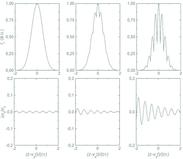
Figure 2.2: Principle of forward Raman scattering for three evolving time steps. As a high intensity laser propagates through an underdense plasma with a period of less than the laser pulse length, the amplitude of the plasma wave gets amplified and the laser beam envelope modulated at ω−1
which are assumed to be near to each other can then be expressed as 4L = L∂vg ∂z 4t = − L c ∂vg ∂ψ4t, (2.30)
when 4t represents a change in time while ψ is fixed. Consequently, the rate that two positions bunch towards each other due to variations to vg is given as
1 L ∂L ∂τ = − 1 c ∂vg ∂ψ. (2.31)
Hence, the longitudinal bunching of the laser envelope is caused by longitudinal varia-tions in the group velocity. Since this can induce a loop among these two effects this can result at the end in the full modulation of the laser envelope at ω−1
p .
2.2.1.4 Transverse Laser Focusing
To achieve that electron plasma waves can be used to efficiently accelerate electrons they have to exist over long distances. However, with Eq. 2.3 it is clear that the intensity of a focused laser beam decreases by a factor of 2 over the Rayleigh distance, zR. This
obviously limits the distance over which the plasma wave can grow. However, this can be overcome by the transverse modulation of the refractive index [30].
As the laser focal spot has a spatial Gaussian profile, the maximum velocity of electrons oscillating in the laser beam is higher the closer they are to the center of the focus. As ω2
p ∼ (γ⊥me)−1 the index of refraction of a plasma increases the faster
electrons oscillate. This increase in the refractive index where the intensity across the laser wave front is at its greatest leads to a relative retardation of the wave front and therefore to relativistic self-focusing of the laser beam.
Like it is indicated in Fig. 2.3 the outer part of this wavefront has to curve forward in order to focus the laser beam. For a time interval, 4t, the angle, θ, a wavefront bends forward is
Figure 2.3: Scheme of transverse laser focusing. In case vΦ,1> vΦ,0 the wavefront will bend forward to focus the laser at an angle θ.
2.2. Underdense Plasma 19 θ = − µv Φ,0− vΦ,1 w ¶ 4t. (2.32)
Obviously, energy flows normal to the phase front. Therefore, the transverse component of the energy velocity is c sin θ and the energy is focused inwards with a velocity close to cθ, if θ is assumed to be small. This velocity is equal to the time rate of change of the laser spot size, thus
∂w ∂τ = −cθ = c µv Φ,0− vΦ,1 w ¶ 4t. (2.33)
Differentiating with respect to time gives
∂2w ∂τ2 = c µv Φ,0− vΦ,1 w ¶ , (2.34)
which is the acceleration of the spot size caused by transverse variations in vΦ. Note
that if vΦ,0 > vΦ,1 then the spot size increases, hence, defocusing occurs.
2.2.1.5 Photon Acceleration
In photon acceleration, the local frequency changes because of longitudinal varia-tions in vΦ. As the laser phase front moves in a time interval, 4t, a certain distance
according to their phase velocity, one can write the time rate of change of the laser frequency 1 ωL ∂ωL ∂τ = 1 c ∂vΦ ∂ψ, (2.35)
using the speed of light variables. Therefore, as a photon moves along in an index of refraction gradient which it views as stationary, its frequency increases if the slope is positive. This process is called photon acceleration since the waves’s frequency is directly related to vg [31].
In summary, up to now it has been shown that variations in the relativistic group and phase velocity of the refractive index in a plasma wave lead to a modulation of the laser envelope and consequently to different laser intensities. As these processes feed back on themselves the generated plasma wave is amplified. Their growth rates will be dealt with in the next section.
2.2.2
Plasma Wave Growth Rates
In this section the growth rates of the aforementioned instabilities will be discussed. It will be shown, that the interplay between the modulation of the laser envelope and relativistic self-focusing can dramatically increase the amplitude of the excited plasma wave, which can result in the generation of an electron beam.
2.2.2.1 Raman Forward Scattering
In the 1D limit, the laser intensity can only be modulated by laser focusing and photon acceleration. Hence, Eq. 2.29 simplifies to
4ha2i = −4L L ha
2i − 4ωL
ωL
ha2i, (2.36)
and evolves in time as
∂ha2i ∂τ = − 1 L ∂L ∂τha 2i − 1 ωL ∂ωL ∂τ ha 2i. (2.37)
Since in FRS the modulations to n are solely the result of modulations to δne, this
can be rewritten by applying the above given expressions for transverse focusing and photon acceleration as ∂4ha2i ∂τ = − ω2 p ω2 L ha2i ∂ ∂ψ δne ne . (2.38)
Defining δne/ne = (n1/2) exp i(kpz − ωpt) + cc, where n1 depends slowly with both ψ
as well as τ and a = (a0/2) exp i(kLz − ωLt) + cc this results in
∂4ha2i ∂τ = ic ω2 p ω2 L kpa 2 0 2 δne ne . (2.39)
Consequently, in FRS the modulations to ha2i are π/2 out of phase with the density
response, δne/ne.
To decipher the FRS growth rate the well known harmonic oscillator equation is used as this equation describes how modulations to ha2i cause density perturbations
[30]. With the speed of light variables this equation becomes
à ∂2 ∂ψ2 + ω 2 p ! δne ne = ∂ 2 ∂ψ2 ha2i 2 . (2.40)
2.2. Underdense Plasma 21
In [28] it was shown in detail that this equation leads to the growth rate of FRS given by ∂2 ∂ψ∂τha 2i 1 = k2 pc2 8 ω2 p ω2 L a2 0ha2i1, (2.41) with 4ha2i = ha 2i 1 2 exp (−iωpψ) + cc, (2.42)
which leads to the asymptotic solution
ha2i 1 ∼ exp à a0 √ 2 ωp ω0 ωp q ψτ ! . (2.43)
Clearly, for the example of the 800 fs laser pulse duration given for the noise-source the gain induced by a 1 µm laser is about 3 × 10⁵. Analyzing ha2i
1 as a function of the
normalized laser vector potential it is evident that the growth rate has a maximum at
a0 = 1. The reason for this is that ωp is inversely proportional to √me. As the laser
intensity increases, the quiver velocity of the electrons increases, the plasma frequency decreases and so does the gain.
2.2.2.2 Relativistic Self-Focusing
The evolution of a laser beam focus with a Gaussian profile was given in Eq. 2.3. Considering nearly planar wavefronts, i.e., regions near the focus, this equation can be differentiated twice to get
∂2w ∂τ2 ≈ 4 k2 Lw03 , (2.44)
which has to be added to Eq. 2.34 since in the absence of variations in vΦ the spot size
increases due to diffraction. Hence,
∂2w ∂τ2 = 4 k2 Lw30 Ã 1 − a 2 0 32w 2 0 ω2 p c2 ! . (2.45)
As self-focusing occurs if the term in brackets is negative a laser power threshold, Pc,
for relativistic self-focusing to occur is given in (TW) as
Pc = 8π ²0m2ec5 e2 nc ne = 1.7 × 10⁻²nc ne . (2.46)
This laser power threshold is for a 1 µm laser propagating through a plasma with an electron density of 1019 cm−3 about 1.9 TW.
Complete expulsion of electrons from the laser focal spot due to the laser pondero-motive force not only enhances self-focusing of the laser beam but can also serve to guide the laser over many Rayleigh lengths [32, 33]. As relativistic self-focusing changes the normalized vector potential of the laser this modifies the plasma refractive index. Consequently, multiple foci are possible as the laser propagates through the plasma [34].
In conclusion, due to the modulation of the refractive index of a relativistic plasma wave an interplay between FRS and the self-modulation of the laser beam envelope is initiated. This can resonantly drive an initial plasma wake to high amplitude. If additionally the laser power is beyond the threshold for relativistic self-focusing this plasma wave can grow over distances exceeding the diffraction limit of the laser. As a result this can lead to the generation of an energetic electron beam as will be shown in the following.
2.2.3
Wavebreaking – Electron Beam Generation
So far it has been shown that the interaction of a high-intensity laser with an under-dense plasma can create electron plasma waves. In the self-modulated laser wakefield (SMLWF) regime these plasma waves are the electron source themselves once they break and accelerate background electrons. In the following the accelerating fields as well as the energy gain of these electrons will be deciphered.
2.2.3.1 Wavebreaking
Principally, an electron beam provided by an external source can be injected into an electron plasma wave as long as the electron beam energy fulfills the trapping condition mentioned below. However, in the SMLWF regime this electron plasma wave is the electron source itself [7]. Here, plasma electrons are accelerated once the amplitude of the plasma wave has exceeded a limiting value known as wavebreaking. This wavebreaking occurs because some of the plasma electrons undergo such large oscillations that the returning force due to the plasma wave is no longer large enough to make them continue their longitudinal oscillation. Instead the electrons can continue into the next wave ‘bucket.’ If this is the forward travelling ‘bucket,’ then the electron, instead of feeling a returning force, will feel a continued acceleration, so resulting in its trapping within the plasma wave. The trapped electrons continue to be accelerated until their velocity exceeds that of the plasma wave and “out-run” the wave and are dephased.
2.2. Underdense Plasma 23
2.2.3.2 Acceleration Fields Linear Case
Longitudinal electron plasma waves can be described as δne/ne = δ sin[kp(z − vΦt)],
where δ is the plasma wave amplitude. From Poisson’s equation it is possible to derive the amplitude of the associated longitudinal accelerating fields, Ep, by
∇ ·−E→p = −e
δne
²0
= −Ep0sin[kp(z − vΦt)], (2.47)
where Ep0= δEmax. For the maximum plasma wave amplitude, δ = 1, this leads to
Emax =
ene
²0kp
= mecωp
e . (2.48)
Hence, for an electron plasma density of 1019 cm−3 electric fields of the order of 300
GV/m are attainable. However, these expressions solely account for perfectly sinusoidal plasma waves.
Nonlinear Case
Since such plasma waves grow from FRS their amplitudes can increase drastically. This can result in a nonlinear behavior of these waves, from which they can loose their sinusoidal profile. This consequently changes the accelerating fields [35, 36]. In [37] it was calculated that the limit for this accelerating field, EW B, is in the relativistic case
EW B =
q
2γ⊥(γp− 1)Emax, (2.49)
where γp = (1 − βp)−1/2 is the relativistic Lorentz factor of the electron plasma wave,
with βp = vΦ/c. Hence, in this case, Emax can even be enhanced by a factor of 6 for
an electron density of 1019 cm−3.
Plasma Heating
So far the amplitude of electron plasma waves has been described by δ = δne/ne.
Obviously, the impact of the (1 − δ) additional plasma electrons has been neglected. Their movement can be integrated to a temperature, Te, which changes the
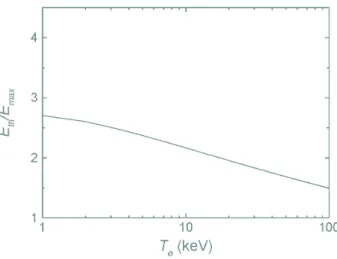
wavebreak-ing threshold, Eth, according to [38] as
Eth= Ã mec2 3Te !1/4vu u tln " 2√γΦ µ 3T e mec2 ¶1/4# Emax. (2.50)
Figure 2.4: Accelerating field at wavebreaking threshold for a relativistic plasma wave with
γΦ= 10 as a function of ambient electron temperature.
This function is indicated in Fig. 2.4. Obviously, the hotter the ambient electron distribution the lower the accelerating field at wavebreaking.
2.2.3.3 Energy Gain 1D Approach
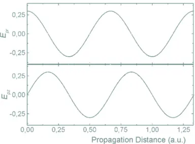
Due to their oscillation electron plasma waves have accelerating as well as deceler-ating segments like it is indicated in Fig. 2.5. Obviously, an electron is only accelerated
Figure 2.5: Plasma wave (solid line) in one dimension with the associated electric field (dashed line), including decelerating (a) and accelerating (b) segments.
2.2. Underdense Plasma 25
over kp(Ldeph− vΦt) = π, where Ldeph is the dephasing length, which is the length over
which an electron at a certain initial velocity gains half a plasma wavelength, which is the accelerating part of ~Ep. Assuming the electron velocity to be about c this dephasing
length then turns out to be
Ldeph =
λp
2(1 − βp)
∼
= γΦ2λp, (2.51)
where λp is the plasma wavelength and in case γp À 1 [39]. Consequently, the maximum
energy, Wmax, an electron can gain in such a plasma wave is
Wmax = eEpLdeph = 2πmec2γΦ2δ. (2.52)
2D Approach
However, a plasma wave has a finite transverse dimension, which must be considered in a 2D approach as the focal spot of the laser, w0, can be of the order of the plasma
wavelength, λp. In this case the radial component of the electric plasma field either
expels or attracts electrons to the center as it is indicated in Fig. 2.6. Consequently,
Ldeph turns out to be λp/4 in the center of mass frame of the wave, which yields in the
laboratory system to
L2Ddeph ' γΦ2λp
2 . (2.53)
Therefore the maximum energy an electron can gain in a 2D geometry is
W2D
max = πmec2γΦ2δ. (2.54)
2.2.3.4 Trapping Conditions
As it occurs for any acceleration process with oscillating electromagnetic waves, electrons need to have a initial kinetic energy to be trapped in such waves. Therefore, the potential of the wave in the wave frame has to be higher than the particle kinetic energy. In [40] the required injection energy of electrons, Einj, was calculated to be
Einj = γp2 δ + 1 γp − βp v u u tδ Ã δ + 2 γp ! − 1. (2.55)
In this case the electron is assumed at the minimum of the potential of the plasma wave so that it requires the minimum trapping condition and the maximum energy
Figure 2.6: Accelerating and focusing segments for radial, Epr, and longitudinal, Epz,
seg-ments of a 2D plasma wave. In the wave frame Ldep turns out to be λp/4.
gain can be obtained. Analyzing Eq. 2.55 as a function of δ, it is evident that Einj
is negligible when the plasma wave amplitude approaches 1. Consequently any free electron is trapped independently of the plasma wave velocity.
So far, mainly the motions of electrons during the interaction of a high-intensity laser with a plasma have been regarded. Due to their much higher mass, these oscilla-tions are in general too rapid for ions. However, if charge separation occurs over longer timescales, ions can react on the generated fields, as the mechanism of the Coulomb explosion shows.
2.2.4
Coulomb Explosion – Ion Beam Generation
The ponderomotive force, ~Fp, was introduced in Chapter 2.1.1.2 as a function of the
laser intensity gradient, which can expel electrons from the region of highest intensity. For relativistic laser intensities this ponderomotive force was in [41] shown to be
~
Fp = ∇(γ⊥− 1)mec2. (2.56)
As it will be discussed later in Chapter 2.3.1 this ponderomotive force, ~Fp, accelerates
electrons to a Maxwellian-like energy distribution, which has an effective temperature,
TvB = mec2(
q
1 + a2
0− 1). As this induces a space charge separation ions with a mass,
mi, and charge, Z, could be accelerated to a velocity, ui. This acceleration in the field
2.2. Underdense Plasma 27 dui dt = − Z mi à mec2 ∂ ∂rγ⊥+ ∂ ∂rTvB ! . (2.57)
Influence of Laser Pulse Duration
An important aspect for this acceleration is the laser pulse duration, τ0, compared
to w0/ui. If τ0 ¿ w0/ui, ions located in the laser focal spot do not have enough time
to acquire the maximum possible energy, whilst for τ0 À w0/ui these ions have already
left the region of interaction long before the laser pulse terminates. Consequently, there is a minimum laser pulse duration for efficient acceleration, which is in (ps) given by
τ0 ≥
0.1 w0
√
γ⊥− 1
, (2.58)
when w0 is expressed in (µm) and the approximation A ' 2Z is made, where A is
the atomic number of the accelerated ion [43]. For this reason ion acceleration by this so-called Coulomb explosion is not feasible with laser pulse durations of some tens of fs with today’s laser parameters, since the energy gain would be low. Assuming the focal waist to be about 10 µm for a normalized laser vector potential of 3, the optimum laser pulse duration should typically be about 1 ps.
Ion Energy Gain
Combining the last two equations a maximum ion energy, Umax, attainable from
this Coulomb explosion can be derived as
Umax= Zmec2(γ⊥− 1). (2.59)
Hence, with a normalized laser vector potential of 6 delivered by a laser with a duration of 0.9 ps which is focused down to a waist of 5 µm, a maximum kinetic energy of 3.4 MeV can be obtained for He2+ ions [44].
In conclusion, it has been shown that the interaction of a high-intensity laser with an underdense plasma can generate large amplitude electron plasma waves due to such phenomena as FRS, modulation of the laser beam envelope and relativistic self-focusing. In the SMLWF regime these waves can break and accelerate background electrons on the laser beam axis. These electron plasma wave oscillations are for ions too rapid since their mass is much larger than the electron mass. However, due to the laser ponderomotive force large space charge fields can be induced in the focal spot, which are capable to accelerate ions radially to the laser axis. This Coulomb explosion
is up to now the only experimentally known ion acceleration process in the underdense regime with short pulse lasers.
It is noted, that the mechanisms for the underdense regime can also occur when such high-intensity lasers are focused onto solid targets. This is due to the technological enigma that such laser impulsions are always headed by a laser prepulse, which can be sufficient to create a preplasma in the target. As plasmas expand into vacuum [13], their electron density can drop underneath the value of the critical density before the main impulsion arrives. In this low density plasma some of the above mentioned mechanisms can occur.
2.3
Overdense Plasma
Obviously, the resonantly amplified generation of a large amplitude electron plasma wave cannot occur in a purely overdense plasma, because the laser beam is prevented from propagating, since ωL < ωp. However, plasma electrons can nevertheless be
accelerated in the plasma skin layer by the laser ponderomotive force. This mechanism as well as the secondary and resulting processes for proton acceleration induced by this charge separation will be presented in the following sections.
2.3.1
~v × ~
B Heating – Electron Beam Generation
For very short and relativistic laser pulses, the ponderomotive force, ~Fp, can become
very important and the resulting acceleration will tend to push electrons in front of the laser pulse, as a kind of snow-plough effect. This was formerly explained by the influence of the Lorentz force, which is proportional to ~v × ~B. Even though this effect
can obviously also occur in the underdense regime it is in the purely overdense regime the main electron acceleration mechanism.
For a short density gradient scale length, d > λL, where d−1 = n−1e dne/dz, electrons
can escape from the laser field in a single optical cycle with a kinetic energy, which is related to the ponderomotive laser potential, Umax. In [45] it was suggested that at
laser field intensities beyond the relativistic value, a0 ≥ 1, such electrons are accelerated
to a Boltzmann-like distribution with a temperature, which is of the same order of magnitude as the energy of electron oscillations in the laser field. This is in qualitative agreement with numerical simulations [46]. Hence, this temperature, TvB, is in (MeV)
given as TvB = mec2 µq 1 + a2 0− 1 ¶ ≈ 0.511 s 1 + I18λ 2 L 1.37 − 1 , (2.60)
2.3. Overdense Plasma 29
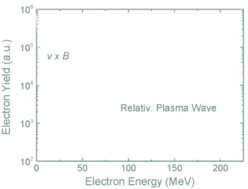
Figure 2.7: Schematic electron spectra for ~v × ~B electron acceleration and those induced by
relativistic plasma waves.
when λL is expressed in (µm). Clearly, if a 1 µm laser is focused down to an intensity
of 1019 W/cm2 the temperature of this electron distribution is about 1 MeV.
Difference between ~v × ~B Heating and Acceleration by Relativistic Plasma
Waves
As mentioned above, the ~v × ~B heating process can occur in any kind of plasma as it
is simply induced by the ponderomotive laser potential. However, the maximum energy an electron can gain by this process is limited by the maximum laser intensity. Even with those being beyond 1019 W/cm2, only a maximum electron energy of 3 MeV was
experimentally obtained since the acceleration length is limited due to the evanescence of the laser to only one optical cycle [47]. In contrast, the electron energy gain by large-amplitude relativistic plasma waves is way more efficient, since the acceleration distance can be much longer, possibly beyond zR, if it is favored by relativistic self-focusing
[7]. As both of these processes can occur simultaneously in the underdense regime, electron spectra obtained here are the superposition of both these mechanisms. This is indicated in Fig. 2.7. In PIC simulations and experiments it was already observed that the ~v × ~B mechanism leads to a much higher electron yield as well as a larger angular
distribution. Since the total number of accelerated electrons can even be of the order of the critical density, this can clearly exceed the low-energy electron yield attainable from wavebreaking [48].
As the laser ponderomotive force pushes electrons out of the laser focal spot this plasma region becomes positively charged shortly after the passage of the laser pulse. This space charge separation as well as the generated electron beam leads to a secondary acceleration process that acts on the remaining positive ions.
2.3.2
Electrostatic Field – Proton Beam Generation
For lucidity the subsequently presented ion acceleration mechanisms by laser plasma interactions will be restricted for protons only, since their acceleration was the aim of the experiments presented here. It is noted that the given formulas also account for any other ion, when the different mass as well as charge are corrected.
In the following, two recently published formalisms will be presented, which describe the mechanisms in which these accelerated protons have their origin
1. at the front surface of the target the laser is focused onto [49], and 2. at the target back surface [50].
The main difference between these two possibilities is that for the front surface mechanism the laser sets up a space charge field, which is induced by the ~v × ~B heating
of electrons. In contrast, proton acceleration from the target back surface is due to the space charge field created by electrons propagating through the target and escaping into vacuum. It is emphasized that both possibilities occur in experiments.
2.3.2.1 Laser Ponderomotive Push
Following [49] it is possible to determine a relation between the laser intensity and the maximum kinetic ion energy, which they obtain at the front target surface. Additionally, the opening cone of this ion beam can also be deciphered.
Ion Energy Gain
A laser pulse incident at a sharp boundary of an overdense plasma exerts on elec-trons in the skin layer the ponderomotive force, ~Fp. This force pushes electrons from
their equilibrium positions into the plasma until it is balanced by the electrostatic field,
Es, which is induced due to this charge separation. This field was estimated to be
Es ≈ mecωL 2e a2 0 q 1 + a20 2 , (2.61)
and it is this electrostatic field that accelerates ions into the target. The mean recession velocity of protons, vr, was in [45] estimated from balancing the momentum flux of the
ions with light pressure. In case of total back reflection of the laser beam, vr is found
to be vr = a0c s me mp nc ner , (2.62)
![Table 2.1: Ionization energies [22] and resulting intensity thresholds according to the BSI model for deuterium and helium.](https://thumb-eu.123doks.com/thumbv2/123doknet/2628913.58927/22.918.253.632.973.1120/table-ionization-energies-resulting-intensity-thresholds-according-deuterium.webp)