Université de Montréal
Routing and dimensioning
0f
3G mufti-service
networks
par
Raha Pooyania
Département d’informatique et
de recherche opérationnelle
Faculté des arts et des sciences
Mémoire présenté à la Faculté des études supérieures
en vue de l’obtention du grade de
Maître ès sciences (M. Se.)
en informatique
Avril, 2004
Copyright
©
Raha Pooama, 2004
c
t)5L1
C
Université
(111
de Montréal
Direction des bibliothèques
AVIS
L’auteur a autorisé l’Université de Montréal à reproduire et diffuser, en totalité ou en partie, par quelque moyen que ce soit et sur quelque support que ce soit, et exclusivement à des fins non lucratives d’enseignement et de
recherche, des copies de ce mémoire ou de cette thèse.
L’auteur et les coauteurs le cas échéant conservent la propriété du droit
d’auteur et des droits moraux qui protègent ce document. Ni la thèse ou le
mémoire, ni des extraits substantiels de ce document, ne doivent être imprimés ou autrement reproduits sans l’autorisation de l’auteur.
Afin de se conformer à la Loi canadienne sur la protection des renseignements personnels, quelques formulaires secondaires, coordonnées
ou signatures intégrées au texte ont pu être enlevés de ce document. Bien
que cela ait pu affecter la pagination, il n’y a aucun contenu manquant.
NOTICE
The author of this thesis or dissertation has granted a nonexclusive license allowing Université de Montréal to reproduce and publish the document, in part or in whole, and in any format, solely for noncommercial educational and
research purposes.
The author and co-authors if applicable retain copyright ownership and moral
rights in this document. Neither the whole thesis or dissertation, not
substantial extracts from it, may be printed or otherwise reproduced without the author’s permission.
In compliance with the Canadian Privacy Act some supporting forms, contact
information or signatures may have been removed from the document. While this may affect the document page count, it does not represent any loss of
Faculté des études supérieures
Ce mémoire intitulé
Routing and dimensioning of 3G multi-service networks
préseuté par Raha Pooyania
a été évalué par un jury composé des personnes suivantes
i’vIichel Gendreau
(président-rapporteur) Brigitte Jaumard (directeur de maîtrise)
Bernard Gend ron (membre du jury)
Viémoire accepté le
Sommaire
La demande élevée de bande passante pour accéder aux différents types d’application, en particulier les applications multimédia, à partir d’une station mobile tout en satis faisant une certaine qualité de service correspond au nouveau visage des réseaux sans
fil de troisième génération. Le besoin accru en ressources de la part des applications
multimédia, attire l’attention sur les outils de dhnensioimement.
Le but de ce mémoire de M.Sc. est la généralisation d’un modèle mathématique développé dans la thèse de M.Sc. de C. Voisin pour le dimensionnement de réseaux
3G en ce qui concerne les aspects de routage. En effet, l’objectif est d’étudier l’impact
d’une politique de multi-routage versus une politique de mono-routage sur le coût de dimensionnenwnt.
Le modèle généralisé correspond à un programme mathématique linéaire mixte en
variables O-1. La validation et les expériences informatiques comparatives ont été faites sur divers exemples de trafic avec différentes caractéristiques. Bien que des expériences aient été faites seulement sur des réseaux de taille limitée, il est déjà possible de mettre en évidence un avantage clair du multi-routage en comparaison du mono-routage.
Mots clés : Réseau 3G, CDMA2000, Dimensionnement, Multi-routage, Contrôle d’admission, Soft handoff, Capacité radio, GdS, QdS.
Abstract
The high demand of bandwidth for access to different kinds of applications, especially multimedia applications, by a mobile station, while satisfying their requested Quality of Service, is the new face of third generation of networks. The need of multimedia applications for high bandwidth, convey the researches to dimensioning tools.
The purpose of this M.Sc. Thesis is the generalization of a mathematical model developed in the M.Sc. Thesis of C. Voisin for the dimensioning of 3G networks with respect to the routing aspects. Indeed, the objective is to study the impact of a multi versus a mono routing path policy on the dimensioning cost.
The generalized model corresponds to a linear mixed mathematical program with
O-1 variables. Validation and comparative computational experiences have been per formed on various traffic instances with different characteristics. Although experiments have been performed on a network with limited size, there is already a clear advantage of multi-routing over mono-routing.
Keywords: 3G Network, CDMA2000, Dimensioning, Multi-routing, CalI Admission Control, Soft handoif, Radio capacity, GoS, QoS.
Table of contents
Sommaire iii
Abstract iv
Table of contents y
List of tables x
List of figures xii
List of abbreviations xv
Dedication viii
Acknowledgment xix
1 Introduction 1
1.1 Motivation 1
1.2 Plan of the thesis 3
1.3 Contributions 4
2 Architecture of the CDMA2000 Networks and Multimedia Services 5
2.2 What is CDMA Tecio1ogy 7
2.2.1 CDMA2000 and UMTS 10
2.3 Architecture of the CDMA2000 access networks 11
2.4 Core Network 14
2.5 Radio Access Network 15
2.5.1 Ceil spiitting 15 2.5.2 Handoif 16 2.6 Quality of Service 1$ 2.6.1 Non-real-tirne application 19 2.6.2 Real-tirne application 20 2.7 Service Classes 21 2.8 Integrated Services 22 2.8.1 Plow specification 22 2.8.2 Routing 23 2.8.3 Resource reservation 24
2.8.4 CaIl Admission Control 25
2.8.5 Packet scheduling 27
3 Literature Review 31
3.1 Core network dimensioning 32
3.3 Core network and radio network dimensioning 3.4 Conclusion
4 Dimensioning Strategy and Network Modeling
4.1 Network modeling
4.1.1 3G network architecture 4.1.2 Distribution of the BSCs and 4.1.3 Soft handoif
4.1.4 Capacity of the radio links 4.1.5 Cail Admission Control . 4.2 Traffic modeling
4.2.1 Generation of sessions . .
4.3 Routing 4.4 Delay
4.4.1 Delay on wired link part . 4.4.2 Delay on radio link part .
4.5 Dimensioning strategy
5 Mathematical Model
5.1 Notations
5.1.1 General notations 5.1.2 Wired link pararneters
vil 42 43 44 base stations 47 76 77 77 78
5.1.3 Routing parameters . 78
5.1.4 Session parameters . . 79
5.2 Definition of the variables . . 80
5.3 Objective function 82
5.4 Constraints 82
5.4.1 Cail Admission Control 82
5.4.2 Link between wired part and radio part 84
5.4.3 Quality of Service: Delay 85
5.4.4 Capacity of wired links 86
5.4.5 Capacity of radio links 88
5.4.6 Grade of Service 90
5.4.7 Handshake between a BSG and a base station 90
5.4.8 Soft handoif 92
5.4.9 Quality of Service: Selection of a RAB on the radio links . . 94
5.4.10 Activation of a base station 97
5.5 Bounds and domains of the variables: Summing np 98
5.6 Diinensioning mathematical model: Summing up 98
5.7 Improved model 104
5.7.1 Improved dimensioning matheinatical model: Summing Up . . . 107
6.1 Instance generator 110
6.1.1 Network architecture 111
6.1.2 Simulation space, base stations, base stations in soft handoif and
paths 111
6.1.3 Initial solution 112
6.1.4 Simulation planning time 112
6.1.5 Session generation 113
6.1.6 Session position 116
6.1.7 Choice of base stations 117
6.1.8 Choice of paths 119
6.2 Variables and constraints of the MIP program 119 6.2.1 Parameter values in objective function 120
6.2.2 Values for bandwidth of the fiow 120
6.2.3 Set of RABs, values for ratio of signal to noise
7s,r
and Quality of Service coefficientQr,a,p
per application type 121 6.2.4 Numerical values for constant parameters in radio capacity formulas 121 6.2.5 Numerical values for constant parameters in delay formulas . 1236.3 Network topology 123
6.4 Definition of instances 124
6.5 Opthnization procedure: CPLEX 125
6.7 LP value, best integer value and validation of the numerical results . 131
6.8 Numerical results 132
6.8.1 Impact of multi-routing 132
6.8.2 Impact of the number of periods 133
6.8.3 Impact of the session length 136
6.8.4 Grade of Service 137
6.8.5 Conclusion 139
7 Conclusion and Perspectives 141
Bibliography xx
A Leaky bucket xxv
B Selective Repeat Protocol xxvii
List of tables
2.1 CDMA2000 and UMTS comparison .
2.2 Service classes
2.3 Comparison table for the scheduling policies
3.1 Comparison table 34
RAB combinations in RC4
Applications in the traffic model Table of values for R(rt)
Radio transmission delay of a frame
5.1 Value of the QoS coefficients for web browsing downlink
6.1 Session specifications based on its type of application
6.2 Application utilization by the users
6.3 Parameter values for the voice application 6.4 Parameter values for the videophone application
6.5 Parameter values for the video streaming application
114 114 115 116 116 11 22 29 4.1 4.2 4.3 4.4 50 59 64 72
6.6 Parameter values for the web browsing application 116
6.7 Parameter values for the mail application 117
6.8 Bandwidth on radio links for CBR applications 121
6.9 Bandwidth on wired links for CBR applications 121
6.10 Bandwidth on radio links for VBR applications 122
6.11 Bandwidth on wired links for VBR applications 122
6.12 Parameter values for capacity formulas 122
6.13 Value of parameters in delay formula 123
6.14 Instance I 126
6.15 Instance II 127
6.16 Value of CPLEX parameters 130
6.17 Comparing results when number of periods is 6 133
6.18 Comparing resuits when number of periods is 10 134
6.19 Comparing results for the impact of sessions length 136 6.20 Demanded and obtained GoS for ail applications 137 6.21 Demanded and accepted nuniber of voice sessions in each period . 138
List of figures
2.1 Evolution of the communication networks 8
2.2 CDMA - FDMA - TDMA 9
2.3 CDMA2000 12 2.4 Soft handoif 18 2.5 Softer handoif 18 4.1 Network model 46 4.2 Distribution of BSCs and BSs 47 4.3 Temporal sequencing 61 4.4 Flows 62 4.5 Selection of paths I 66 4.6 Selection of paths II 67 4.7 Dimensioning procedure 73
4.8 The result of dimensioning 74
6.2 Topology of the network 124
6.3 Branching tree 128
6.4 An Example of core network 131
6.5 Comparing mono-routing and multi-routing 131
6.6 Comparing the LP and best integer values in mono and multi-routing 132
6.7 Comparing sessions in 6 and 10 periods 135
6.8 Impact of increasing the number of periods during a planning time . 136
6.9 Obtained GoS during each period for the voice application 139
List of abbreviations
2G Second Generation Cellular Mobile Systems
3G Third Generation Cellular Mobile Systems
4G Fourth Generation Cellular Mobile Systems
AAA Authentication, Authorization and Accounting
AMPS Advanced Mobile Phone System
BGP Border Gateway Protocol
BS Base Station
BSC Base Station Controller
CAC Cail Admission Control
CBR Constant Bit Rate
CDMA Code Division Multiple Access
CN Core Network
DL DownLink
DS-WCDMA Direct Sequence Wide-band CDMA
FA Foreign Agent
FCFS First Come First Served
fDD Frequency Division Duplex
FDMA Frequency Division Multiple Access
FER Frame Error Rate
FIFO First In First Out
FTP File Transfer Protocol
GPRS General Packet Radio Service
GPS Global Positioning System
GPS General Processor Sharing
GSM Global System for Mobile Communication
HA Home Agent
INTSERV Integrated Services
IP Internet Protocol
MC-CDMA Mufti Carrier CDMA
MIP Mobile Internet Protocol
MS Mobile Station
MSC Mobile Switching Center
OSPP Open Shortest Path First
PCF Packet Control Function
PDSN Packet Data Serving Node
PGPS Packet by packet General Processor Sharing
PPP Point to Point Protocol
PSTN Public Switched Telephone Network
Q0S Quality of Service
RAB Radio Access Bearer
RAN Radio Access Network
RIP Routing Information Protocol
RN Radio Network
RPPS Rate Proportional Processor Sharing
RRC Radio Resource Control
RTP Real-tirne Transport Protocol
SIR Signal to Interference Ratio
TCP Transmission Control Protocol
TDD Time Division Duplex
TDMA Time Division Multiplex Access
UL UpLink
UMTS Universal Mobile Teleconrniunications System
VBR Variable Bit Rate
WCDMA Wide-band Code Division Multiple Access
WFQ Weighted Pair Queuing
In the name of the Lord of wisdom andmmd,
To nothing sublimer can thought be appfied.
Acknowledgment s
Mv sincere gratitude to my supervisor Professor Brigitte Jaumard for her enthusiasm, integrai view
on research, stimulation suggestion, rich comments, kindness, understanding and the financiai support.
I am really glad that I had this opportunity to knowmy friend, Dr. C’hristophe Meyer, who helped me alt the way in this thesis. Thanks for valuable discussion, constant encouragement and availabifity.
My appreciation to the jury committee, Professor Michel Gendreau and Professor Bern ard Gendron who accepted b read my thesis and for their useful comments which helped me b complete this study.
Thanks to the De’partement d’informatique et recherche oplrationnelle (IRO) and the Centre de recherche sur les transports (C’RT,) for their support and the excellent environment for studving.
A special thank to my great parents, who taught me the good things that reaily matter in fife.
I deeply appreciate your unconditional love, support, sacrifices and heing a source of pride for me. I thank my amazing sister, my kind brother and brother-in-law and my lovely nephew for their pure love and encouragement.
To my caring grand-parents, memory of my late grand-parents and other mem bers of family and
friends for their inspiration and moral support. Thanks bo ail my friends in Iran and Canada, Ah, Akbar, Hichem, Pvlaryam, Mahboobeh, Nourchen, Rose, Shiva, Salim... for their precious friendship.
And at hast to my beioved husband, Vahid, whose endless support has allowed me to chase a dream. Thanks for your love, patience, heip, understanding and believing in me through ail this long process.
Introduction
1.1
Motivation
Communication has aiways been an essential part of every kind of human society. So
far, many technologies have been developed for this purpose. Among these, mobile coin munication has been one of the most important technologies that man has ever used. The abiilties of the second generation telecommunication systems, such as GSM (Global System for Mobile Communication), are lirnited to digital wireless voice traffic. These systems have been designed for voice communications with low-bit-rate data services. Any enhancement or addition of new services also affects the service. Growing dernands for transferring high quality images, video and wireless Internet access with high data rate (up to 2 mbps) and needs for data-rich, multimedia services accessed instantly over mobile handsets forced the technology to move to Third Generation Telecommunication Systems (3G) and Fourth Generation Telecommunication Systems (4G).
Every telecommmiication operator, developer or vendor in the world is affected by this technology since telecommunications evolve toward a new generation of networks, ser vices and applications. The third and fourth generations of networks are the new faces of wireless network technologies, which have been significantly improved in terms of system capacity, voice quality, and ea.se of use.
In Japan, telecommunication systems are very close to 4G, based on WCDMA, whose main advantage over 3G is the availability of higher bandwidth. While in North Amer ica, the technology is stili with 3G. Among the 3G standards, WCDMA (Wide-hand Code Division Multiple Access) and CDMA2000 are the most used third generation air interfaces. 3G combines high-speed mobile access with Internet Protocol (IP) based
services but it does not concern a super fast connection of mobile communications.
3G is expected to support enhanced multi-media such as voice, data, video and remote
control in all known modes such as cellular telephone, e-mail, fax, videoconferencing, web browsing and other services.
The demand of bandwidth is obvious for all kinds of applications. The fixed network can handie the high data rate, but not the Quality of Service (QoS) demands for the uew multi-media applications. The goal of the first applications over Internet, such as FTP (File nftansfer Protocol), was to have a reliable connection without considering the delay. The best effort connection cannot satisfy the QoS demands of each application either. The new real-time multi-media applications such as videophone, not only need
a high data rate but are also very sensitive to delay. Therefore, we need mechanisms
to provide the requested Quality of Service for each type of applications. The need for
a high data rate and QoS in radio links is another challenge for 3G networks. This is why in 3G networks the Code Division Multiple Access (CDMA) technology which
diversifies the bandwidth on the radio links has been used.
In order to satisfy mufti-media applications demands, more base stations and advanced equipments are needed. Considering the high prices of these equipments, the use of dimensioning tools with multi-routing strategies are necessary. Therefore, developing mathematical models for network dimensioning that minimize the cost of link capaci ties in the core network as well as the equipments in the radio network under different routing strategies are the objectives of this project. For each requested session from the mobile station, there may be several potential base stations which are ready to support this session and are connected to different Base Station Controllers (BSC). In addition it
is assumed that there may be different routing paths between a given pair of origin and
routing protocols versus mono-routing.
1.2
Plan of the thesis
We start this study by describing the concept of 3G networks, particularly the mech
auisms that influence dimensioning in Chapter 2. Then, in Chapter 3, we concentrate ou the studies that have already been conducted on dimensioning core and radio net works. In Chapter 4, we present the assumptions under which we worked for the traffic modeling, core and radio networks management modeling as well as the parameters to be considered for the dimeusioning strategies.
A mathematical optimization model is formulated in Chapter 5. It is both an improved
version and a generalization for multi-routing of a flrst model developed by C. Voisin in her M.Sc. thesis [1], see also [2]. In this chapter, we explain ail the variables and
constraints as weIl as the objective function. The flrst part of Chapter 6 describes the details of an implementation of the proposed mathematical model and the parameters used in generating the traffic instances. We theu briefly introduce the CPLEX-MIP software which is used to solve the mixed linear problem corresponding to the mathe matical model that has been built in Chapter 5 and discuss the options that are available to solve the mixed linear problem using a branch-and-bound method. We also present some valid inequalities that can be used to reinforce the strength of the linear relaxations
of the mixed linear problem. At the end of this chapter, vie validate the model using
different traffic instances. While respecting the overall Grade of Service, we compare the results of multi-routing and mono-routing on different traffic instances under different assumptions on the number of divisions iii the planning period and on the length of the
sessions. A conclusion based on the resuits that have been obtained and perspectives on future work completes the thesis.
1.3
Contributions
An optimization model for the dimensioning of the 3G networks has been proposed by C.
Voisin in [1], where for each requested session there is always only one path between its
source and destination. In the model of [1], aIl potential base stations whichcan serve
a session are assurned to be connected to the same base station controller. In addition,
the soft handoif can happen only between two potential base stations. However, in practice there are always several possible routing paths between two different nodes and depending on the geographical position of each session it can be served by base stations which are connected to a unique or different base station controllers. On the other hand, when a session is accepted in soft handoif, the serving base stations are not necessarily Iirnited to two. These arguments motivate our new developed mathematical model, generalizing [1] with the rernoval of the above assumptions.
In the model proposed in this thesis the routing path for cadi requested session will be chosen among a set of possible paths by an optirnization model in order to minimize the objective function. Moreover generalizing the model proposed in [1], a session can
be served by base stations connected to more than one base station controller.
1-lence, in the scope of tus study:
A mathernatical model which supports multi-routing in the third generation telecom
munication systems is proposed.
) Different effective mechanisms for dimensioning such as, multi-routing, cali ad mission control, Quality of Service and soft handoff between two or more base stations are considered.
> Tic proposed model, which provides a dimensioning tool that concentrates both
on core and radio networks at the sanie time, is developed.
> The profit of multi-routing over mono-routing while supporting multi-services and optimal dimensioning with various traffic instances is tested, validated and evalu ated.
Architecture of the CDMA2000
Networks and Multimedia
Services
In this chapter, we start with a general overview of CDMA (Code Division Multiple Access), the background technology of 3G networks. We go on with the description of the general concepts that tvill be further used and discussed in Chapter 4 and integrated in the mathematical model in Chapter 5. Indeed, in Chapter 4, we will clearly state the assumptions and the choices that will be made for the mathematical model with respect to those general concepts. Therefore, we will first discuss the concept of third generation mobile communication often cailed 3G as well as its requirements and services.
After taiking about the 3G networks and CDMA technology, we wilI next focus on the CDMA2000 network architecture, which is based on CDMA technology as it corresponds to the main technology choice in North Anierica, see [3]. In particular, we
wiIl discuss the soft handoif concept, different types of services, as well as integrated
services and their specifications. At the end, some classical packet scheduling policies are presented.
2.1
Why 3G and a short history
With the appearance of data communication on the fixed network with World Wide Web (WWW), everybody expects the same ability from mobile network. That means using data services on mobile devices so we will be able to support both voice and data traffic. Fôr a while, the Internet and mobile communications have grown separately, but they join together in 3G networks. Hence, a challenge for 3G is to bring the best features of mobile communications and the Internet together. Third generation telecommunications combine mobile radio with Internet technology to provide consumers with a new world
of rich multi-media services via their mobile phones. 3G enables mobiles to carry videos,
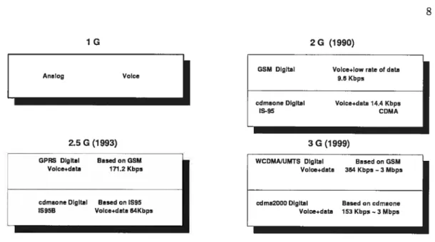
graphics and data, as well as it goes on carrying voice. It promises to deliver anytime, anywhere and anyway access for mobile users. For this reason, the existing 2G systems are replaced by the 3G systems. The flrst 2G systems were launched in the early 1990s with Global System for IVlobile communications (GSM) and Gode Division Multiple Access one (cdmaone). The evolution of the communication networks is illustrated in Figure 2.1. GSM, which is used mostly in Europe, provides a circuit-switched data service and is the most widely adopted mobile standard in the world. With over 578 million subscribers in 400 networks in 171 countries, more than 1 in 10 people on the planet used GSM technology in 2000 [4]. At the beginning the available data rate was around 9.6 kbps and then it reached 14.4 kbps. However, these range of data rates cannot support the high-speed access required for web browsing or email services. In addition, circuit-switched connections, in which a channel is dedicated to a single user, are not very efficient. GSM uses a combination of Frequency Division Multiple Access (FDMA) and Time Division Multiple Access (TDMA) to support multiple access. On the other hand, cdmaone, used in North America, is the first generation of GDMA and
as its name indicates, it uses the GDMA technology to support multiple access by users.
The data rate is about 14.4 kbps in this system. Next, in 2.SG networks, its data rate reached 64 kbps.
The requirements for third generation systems can be listed as below, see [5] for more details:
>- Bit rates up to 2 mbps for stationary users, 384 kbps for pedestrian users and 144
kbps for vehicular users.
>- Multiple simultaneous services.
>- Multiplexing of services with different quality requirements on single coimection,
such as speech, video and packet data.
>- Quality requirements from 10
%
frame error rate to 10_6 bit error rate (corenetwork).
>- Symmetrical and asymmetrical data transmission support (radio network), e.g.,
web browsing causes more loading to downlink than to uplink.
>- Global roaming across networks.
The 3G network has a layered architecture and is divided in two different parts (core and radio parts), which enables an efficient delivery of voice and data services. A layered network architecture, coupled with standardized open interfaces, makes it possible for the network operators to introduce and rolI out new services quickly. These networks have a connectivity layer at the bottom providing support for high quality voice and data delivery. Using IP, this layer handles all data and voice connections. The layer consists of the core network equipments like routers, switches and transmission equipments. The application layer on top provides open application service interfaces enabling flexible service creation. The user application layer coutains services such as e-commerce and GPS (Global Positioning System), for which the end user is willing to pay.
2.2
What is CDMA Technology?
A central base station strategy is used in alI cellular networks. A link between a handset
2G (1990)
GSM Digital Volce+lew rate cf data
Analog Voice 95 Kbps
cdmaone Digital Volce+data 14.4 Kbps
lS-9 CDMA
2.5 G (1993) 3G (1999)
GPRS Digital Based on GSM Volce+data 171.2 Kbps
cdmaone Digital Baaed on 1S95
1S95B Vcice+data 64Kbps
FIG. 2.1: Evolution of the communication networks
the base station and handset is called downlink or forward link (DL). These are broad casting channels in which cadi communication is assigned a unique frequency, a unique time slot or a unique code. The first is known as Frequency Division Multiple Access (FDMA), the second as Time Division Multiple Access (TDMA) whule the last corre sponds to the Code Division Multiple Access (CDMA), see Figure 2.2.
The cellular systems based on FDMA, such as Advanced Mobile Phone System (AMPS), have several disadvantages like the need for guard bands between signais, which reduce the available bandwidth. Meanwhile, a strong signal may capture the whole hand for a long time.
TDMA offers the ability to carry data rates of 64 kbps to 120 mbps (expandable in multiples of 64 kbps), however, it is not without difficulty. Users moving from one cell to another are not assigned a time slot. Thus, if all tirne slots in the next celI are already occupied, a cali might be disconnected. Likewise, if all the time slots in the celI in which a user happens to bein are already occupied, he will not receive a dial tone. In addition, TDMA is less robust to ;nulti-path effects [6]. A signal coming from a tower to a handset might come from any one of several possible paths. It might have bounced
off several differeit obstacles before arriving, which can cause interferences.
•To reach a network, which is able to support wireless data services and applications
1G
WCDMNUMTS Digital Based on (35M
Voice÷data 3M Kbps —3 Mbps
such as wireless email, web browsing and digital picture taldng/sending, the wireiess networks are asked to do much more than a few years ago and vill be asked to do more in the near future. Here, CDMA fits and provides sufficient capacity for voice and data communications ailowing lots of users to connect at any given time. CDMA is the common platform on which 3G technologies are built. This technology was first used in military applications since it was difficult to jam, hard to interfere with and not easy to identify as it looks like noise.
CDMA is a spread spectrum technology and divides the radio spectrum into channels that are 1.25-MHz wide-hand. Unhke FDMA and TDMA, where user signais neyer over lap in either the time or the frequency, CDMA allows many users to occupy the same time and frequency allocation in a given band/space (for more information see [7]). As its naine implies, it assigns unique random codes to each communication to differentiate it from others in the saine spectrum. The number of unique codes in CDMA is equai to the number of users. At the receiver, this code is detected and used to extract the user’s information. The process of moduiation of the signai by unique code is caiied a spreading code, spreading sequence or chip sequence.
CDMA supports two basic modes of operation: Frequency Division Duplex (FDD) and
FIG. 2.2: CDMA - FDMA - TDMA
Time Division Duplex (TDD). In the FDD niode, separate carrier frequencies are used for the uplink and downlink respectiveiy, whereas in TDD only one is time-shared be tween uplink and downlink. CDMA does not accept a large propagation delay between
a mobile station and a base station as it causes sender-receiver collision. CDMA is considered to have nunierous advantages over TDMA and FDMA. CDMA may deliver more information than FDMA and TDMA in a given time period (up to 4 to 6 times).
p Powe,
It supports soft handoif and the problem of using the same frequencies for communi cations within different celis (frequency reuse) does not occur in CDMA. There is also no hard limit on the number of users that we can allow on the system. Each time a user is added, the noise for the other users tvill be increased a little. Another advantage
is that CDMA fights rnulti-path fading due to the faet that the signal is spread over a large bandwidth, and that each path can be tracked separately at the receiver’s end
[7]. CDMA is used in 2G, 2.5G and 3G networks. 2G CDMA is also called cdmaone and includes IS-95. 2.5G CDMA which is based on IS-95 is named IS-95B, while in 3G,
CDIvLk2000 is the most famous 3G service based on CDMA.
2.2.1
CDMA2000 and UMTS
UMTS, originally developed by ETSI, is designed as an evolution from GSM toward WCDMA. The standard for this technology is developed by the 3rd Generation Part nership Project (3GPP). CWTS (China), ETSI (Europe) and TTA (Korea) are coop erating with 3GPP. The offercd data rates are 144 kbps vehicular, 384 kbps pedestrian and 2 mbps when the user is not moving, sec [8]. It uses the already existing GSM
infrastructure. The core network of UMTS can use the current 2G networks for serving voice and packet data.
CDMA2000, developed by Qualcomm and the TIA in North America as a 3G evolution from the existing 2G CDMA system called cdmaone, originally from the IS-95 systems. The standard for this technology is developed by 3GPP2. CDMA2000 allows the si multaneous transmission of voice and data with a data rate of 2 mbps and uses the same equipments as cdmaone. It protects operator investments in existing cdmaone networks and causes a simple and cost-effective migration to 3G services. Comparing the two technologies the system capacities are more or less the same, with a littie ad vantage of tTMTS, but migration from 2G toward 3G is smoother and cost-effective through CDMA2000. Table 2.1 illustrates the teclmical differences between these two technologies based on [8], [5] and
t9]
Air Interface Parameters CDMA2000 UMTS
Carrier Spacing (bandwidth) Nx 1.25 MHz (N=1,3) 5 MHz
Synchronization between ce11 sites Synchronous Asynchronous
Chip rate Nx 1.2288 Mcps (X=l,3) 3.84 Mcps
Frame sue 2040 and 80 msec for physical layer 10 msec for physical layer
Modes PDD FDD and TDD
Multiplexing techniques MC-CDMA DS-WCDMA
TAB. 2.1: CDMA2000 and UMTS comparison
In both UMTS and CDMA2000 the efficient use of available resources such as band width and serving different types of services are the moet important issues.
2.3
Architecture of the CDMA2000 access networks
CDMA2000, which is said to have a 2 mbps data rate, is a true 3G technology based on
CDI\4A technology. It provides higher flexibffity cornpared to the second generation of
networks. In CDMA2000 a Mobile Station (MS) can have access to a service provider network such as Internet. It inciudes two separate parts called Radio Access Network (RAN) and Core Network (CN).
RAN manages the radio links and soft handoif. Actually RAN is not ail radio, there exists a wired part tvhere the base stations are connected to their corresponding Base Station Controiler (BSC). To understand better the functionalities and responsibilities
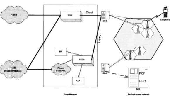
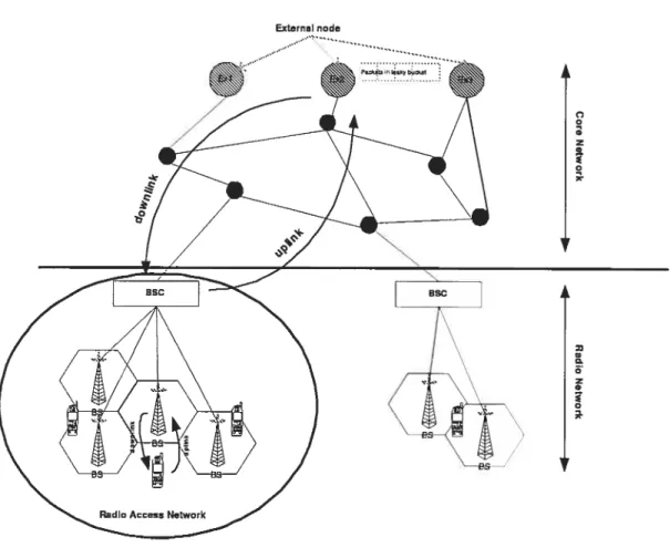
of each part we first discuss about their elements. As shown in Figure 2.3, RAN contains
Base Station (BS) and Base Station Controller (BSC), while the CN contains Packet Data Serving Node (PDSN), Mobile Switching Center (MSC), Authentication, Autho rization and Accounting (AAA) and Home Agent (HA).
• Base Station (BS): Base stations are physicai units of radio transrnission/reception in cells. A celI is a place which is under cover of a BS. A BS lias usually three antennas each covering an angle of 120 degrees. BSs can support both TDD
FIG. 2.3: CDMA2000
and PDD modes. They reiav the cails to and from the mobile stations iocatcd in their coverage areas (ceils). In other words, they provide the radio resources and maintain radio links ta mobile stations. There is aiso a fast pawer contrai algorithm implemented in each base station. It plays a crucial raie in softer handoif when the mobile station is piaced in the overiap of two sectars af the same base station and asks for a session (Section 2.5.2). At this point the invoived base station combines the two upiink signais received from bath sectors. It is important ta mention that each base station is connected ta oniy one BSC and has ail the necessary functions for its own management.
• Base Station Controlier (BSC): BSCs are equipments used as interface with the care network. BSCs contrai the BSs as well as received and sent radio pack ets. They perfarm other radio access and link maintenance functions such as soft handoif and user rnobility in a 3G wireless network. They aiso perforrn voice compression. BSCs cantain twa different components each with specific function ahties.
— Packet Control Punction (PCF): PCF component selects and establislies the connection to the PDSN and forwards the information to it and vice versa. In the soft handoif cases, the serving PCF sends its information to the target PCF to regenerate the packet data session to the PDSN.
— Radio Resource Control (RRC): The RRC supports authentication and au thorization of the mobile stations for their radio access.
As well as a base station, a BSC, has ail the necessary functions for its own management.
• Packet Data Serving Node (PDSN): PDSN is another component in CDMA2000 architecture and acts as a foreign agent. It performs two basic functions. It lias the ability to relay the packets to the mobile stations through the Radio Access Network. Vice versa routing and relaying of the packets to the other IP networks
is another responsibility of the PDSN. It provides foreign agent supports and
also initiates acts as an Authentication, Authorization and Accounting (AAA) for the users. It also manages the Point to Point Protocol (PPP) with the mobile terminal.
• Mobile Switching Center (MSC): This is an interface between Public Switched Telephone Network (PSTN) and wireless system. This server is responsible for verifying the authentication and authorization of the mobile station in the RAN since it stores the authentication and authorization information for the Radio Access Network.
• Authentication, Authorization and Accounting (AAA): The AAA servers interact with the PDSNs (foreign agents) and other AAA servers to perforrn the functions in a secure mode. AAA provides user profile, Quality of Service (QoS) and keeps track of who, what, when and where the sessions are coming from and destined to (Accounting). The AAA server, also contains the data of users who are registered on the network.
• Haine Agent (HA): It maintains user registratian infarmatian and directs IF pack ets ta the PDSN.
2.4
Core Network
The care netwark in CDMA2000 is based an the Mabile Internet Pratacal (MJP) and cannects ta the Public Switched Telephane Netwark (PSTN) ar ather netwarks and alsa manages the rauting. In a Mabile IP, each mabile statian has a canstant IP address and keeps its address even if it mayes araund fram ane paint ta anather. This canstant IP address is called hame IP address. Wheu a mabile statian leaves its hame netwark, a rauter named Hame Agent (HA) (see Sectian 2.3). sends ail carrespanding IP datagrams ta that mabile statian
[1•
The mabile statian will use a Fareign Agent, which is a PDSN, while visiting a foreign netwark. It registers itself in the Fareign Agent and asks far a new address (temparary address). Then, the Fareign Agent sends that address ta the Haine Agent. Therefare in the case af sending a datagram ta that mabile statian, the HA encapsulates that in an IP packet. The destinatian address af this IP packet is the temparary address af the mabile statian. This packet will be sent ta the Fareign Agent. Then, the Fareign Agent decapsulates the IP packet and sends it ta the mabile statian. This methad is the ane which is used in the current care netwarks.
In bath nplink and dawnlink chaasing the praper path amang the existing paths is anather cancern af the care netwark. h mast netwarks, between ail passible paths the shartest path will be chasen.
The netwark architecture used in this thesis cantains the care netwark and is explained in Sectian 4.1.1.
2.5
Radio Access Network
In a Radio Access Network, in order to serve a request of a mobile station two steps should be considered: first, allocation of radio resources and second, establishment of
a PDSN link and PPP session [10]. While a session is sked by a mobile station, a
message with the required packet-data service is sent to BSC. Then the BSC sends a message to MSC in order to ask and authorize a radio traffic channel. If the answer is positive (means that the mobile station is an authorized user of the network) the BSC allocates sufficient resources for the session. Now the mobile station is authenticated and lias enough resources to go on. At this point, the BSC contacts PCF (Packet Control Fiinction) which is responsible to establish a data session with the PDSN. The PCF sends back a message based on fail or acceptance of the session to BSC. Meanwhile,
a Point to Point Protocol (PPP) places between the mobile station and the PDSN to
set up a packet data calI. Once a mobile station has placed a PPP connection to the PDSN, it remains connected to the network.
As it can be seen in Section 4.1.1 the network architecture used in this model contains
the Radio Access Network and its components.
2.5.1 Celi spiitting
In order to increase the capacity of the network and decrease the co-channel interfer ences, the idea of celI splitting was conceived: instead of broadcasting a signal over a vast area we allow to reuse frequencies in each ceIl. This idea involves the base sta tion segmentation into sectors, where there is a separate antenna for each. The most common and used celi splitting is the three sectored celI, Section 2.3. The cell is split into three sectors, with each antenna radiating a 120 degree coverage area, instead of an mono directional antenna. Each sector plays the role of a base station. There is the advantage of a stronger and clearer signal received by mobile station. Note that cell splltting is not considered in the model developed in this thesis.
2.5.2 Handoif
When a mobile station is involved in a session, it is connected to a base station via a ra dio link. One of the advantages of a mobile station is its mobility. To solve the problem
of mobile stations gettingfar from the transmitting base station, handoif is introduced. Handoif occurs when the mobile station is placed in the area covered by two or more different base stations (hard/soft handoif), or when the mobile station is located in an area covered by two antenna sectors of the same base station (softer handoif).
The handoif procedure should be completed while the mobile station is in the overlap area of two or more base stations or the two antennas of a same base station. The strength of the signais and the quality decrease as the MS (Mobile Station) reaches the edge of the coverage area. The connection should be deiivered to the new BS or new antenna before the disconnection of oid BS or antenna from the mobile user. Otherwise the cali is lost [11].
Handoif detection: Making a decision for a handoif should be based on measure ments of the links at the MS and at the base station position. Since the execution of handoif costs enormously, the unnecessary handoifs should be prevented. Therefore the handoif criteria must be chosen properly. However, if the criteria are too strict, then the cail may be lost before the handoif occurs [5].
Hard/Soft handoif
In this case the mobile station is located in the overlap of two or more base stations. It may happen for up to 20 or 40 percent of mobile stations. There are two possibilities in hard/soft handoif [9]:
• Macro diversity: The base stations are connected to different BSCs.
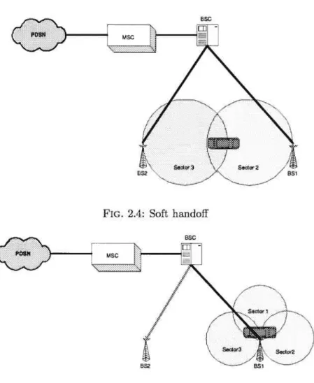
In soft handoif, Figure 2.4, the communications between the base stations and the mobile station is based on one radio channel for each base station in the downllnk direction. Consequently, the mobile station receives two or more signais. In the uplink direction the mobile station sends its signal. The signal will be received by base stations involved in soft handoif. Each base station sends the signal to its corresponding BSC. In micro diversity case the BSC chooses the best received signal while in macro diversity the BSCs con;municate together and then choose the best. While the mobile is moving, if the mobile station leaves the overlap zone both the new and old base stations take care of the session for a certain perfod of time. This improves the transmission quality
of wireless channel and prevents disconnection.
On the contrary, in hard handoif the link to the prior base station is terminated before or as the user is transferred to the new cdl. This means, at any given time a mobile station always communicates with one base station and the old and new radio channels cannot co-exist.
Obvfously, soft handoif is advantageous over hard handoif because the mobile does not loose contact with the system as it avoids interruptions and frequent switching. Nevertheless, soft handoif decreases channel availability since a mobile station may use multiple radio channels at the saine time.
Softer handoif
In this case, the mobile station is located in the overlap of two sectors of the saine base station, see Figure 2.5. It mayhappen for 5 to 10 percent of the mobile stations in a cell. Therefore, each sector uses a radio channel simultaneously. As the mobile station should be abie to distinguish between the signals corning from the two sectors of a base station in the downlink direction, each sigial has its unique code. Mobile station receives both signals and extracts the inforniation. Only the soft handoif will be modeled in Section
2.6
Qia1ity
of Service
With the arrivai of the wireless packet-switched services in the 3G cellular networks, tIre dream of supporting multimedia applications, audio, video and data started to be come true. One of the most important obstacles is the need for high bandwidth links. Recently, thank to improvements in coding, the need for high bandwidth is reduced and tIre speed of links is also increased. However, even with these changes packet-switched networks cannot fulfiul the needs of multimedia as another obstacle rises wInch is tIre time of deiivery.
Our concern is mostly about real-time applications such as voice and video, wInch are
BSG
FIG. 2.4: Soft handoif
BS1
Bsc
8S2
more sensitive to time as they ask for on time data arrivai. Therefore, the best effort model that has been designed for non-real-time applications, and in which the network tries to deliver data but makes no promises, is not satisfying for them.
The need for a new service model where some kind of applications ask the network for higher assurance than others has become very significant. For instance, this model im plies that some packets receive a particular share of bandwidth of the hnks or they neyer have delay more than a certain amount of time. QoS guarantees service requirements such as bandwidth, packet loss rate and delay. A network with these specifications is said to support Quality of Service (QoS).
We should not confuse the QoS with cali service quality. The notion of service quality refers to the delivery of the service in the interaction between the user and the provider, while the QoS concerns the study of the communication services. Obviously, during the connection of two end-users we pass through several networks. At this point, the main issue is to allocate enough resources along the entire path. That is what we caIl End-to-End QoS.
The delay and required QoS for each type of applications are discussed more in details in Chapter 4 and Chapter 5. In this study both non-real-time and real-thne applications are taken in account. Therefore, it is important to have a look at these two types of applications.
2.6.1 Non-real-tirne application
Non-real-time applications let the user to have an interactive communication with a server or one direction communication to another user or machine. Non-real-time ap plications, named also traditional data applications, like telnet and email are not so sensible to time. They can also be accepted and still be usable even with long delays and throughput is the performance goal for them.
2.6.2 Real-tirne application
Real-time applications such as voice and video allow communications between users on
a real-time basis. Time is highly critical for those applications. It does not necessary
mean that it has to be amazingly fast, it means that the tasks must be finished in a predefined time. In the real-time applications, data become digital by an analog to digital converter. Normally data are gathered at a specific rate, then they are placed in a packet and wilI be sent to the destination. It is at this point that the data shonld be played back with the appropriate rate. It seems that each part of data has a play back time. Data is useless if it arrives after its appropriate play back time. That may hap pen because of the delay in the network or because of possible errors and corresponding retransmission of data.
There exist different ways of dealing with this problem. One is to buffer some amonnt of data on receiver level. Therefore vie will always have packets waiting in the buffer to be played back. It means that vie have added a constant offset to the play back time of each packet, so if the packet arrives with a short delay it waits in the queue to be played back but if it arrives with a long delay it does not wait too much in the queue. Meanwhile, the offset time is much more critical for audio applications. It should not pass the 300 ms (as the partners canuot wait more than that to follow the conversation) unless the packet should be discarded. Even the real-time applications have different sensibility to loss of the data. For example, comparing audio to FTP application, loss of one bit may make the file completely wrong and useless.
The developed transport protocol by IETF to meet these requirements of real-time appli cations is Real-tirne Transport Protocol (RTP), which is rather different than Transmis sion Control Protocol (TCP) and with more functionality than User Datagram Protocol (UDP). It has been designed so flexible to support variety of applications, and new ap plications can be developed without revising this protocol.
2.7
Service Classes
The services differ in their level of QoS strictness, which describes how tightly the service
can be bound by specific bandwidth, delay, jitter and loss characteristics [12].
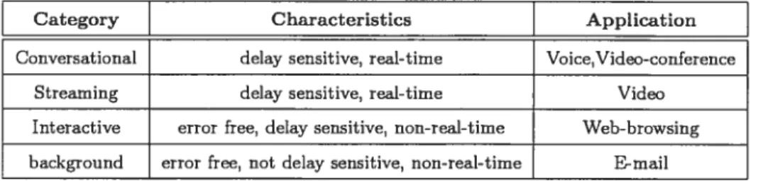
Conversational: Conversational class is a subset of real-time applications and is strongly delay sensitive. It is aiways between two or more persons under the form of voice or video.
Streaming: This class of service is again a subset of real-time applications but is Iess delay sensitive than conversational class. It is aiways between a person and a data server. Transfer of data is from server to the user and can be either audio streaming or video streaming.
Interactive: Interactive class is a non real-time service where the resources are re served dynarnically. Like the streaming class it is between a person and n data server but the connection is in two directions one from human to server (request) and the other from server to human (answer). This class is delay sensitive as well as error sensitive. The transfered data should not be changed under any condition.
Background: The background class, such as mail, is a non real-tirne service. It is not at ail delay sensitive, since the sender of the request neyer asks for a rapid answer in a fixed period of time. On the contrary, this service class is strongly error sensitive and data integrity is an important issue.
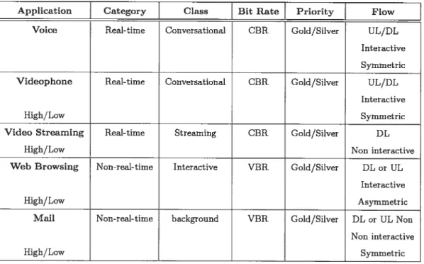
Table 2.2 illustrates n summary of service classes specifications. Ail the mentioned service classes are considered in the traffic instances used in the Chapter 6 in order to test and validate the proposed model.
Category
Characteristics Application
Conversational delay sensitive, real-time Voice, Video-conference
Streaming delay sensitive, real-time Video
Interactive error free, delay sensitive, non-real-time Web-browsing background error free, not delay sensitive, non-real-time E-mail
TAB. 2.2: Service classes
2.8
Integrated Services
In traditional networks, point-to-point best effort delivery wasdone on the model of IP. However, with the appearance of multimedia communications and real-time applications (3G in short), best effort is not an answer due to the sensitivity of the application to delay. In the context of a network with integrated services, different kinds of isolations are needed. At this point, the need for an enhanced QoS (with regard to bandwidth, packet queuing delay, routing and loss) where each individual packet asks for adequate
QoS shows itself. This is what is called Integrated Services (IntServ). This Quality of
Service architecture developed in the IETE around 1995-97 and often associated with Resource Reservation Protocol (RSVP). The following mechanisms are needed in order to satisfy the QoS:
> Flow specification.
> Routing.
> Resource reservation.
> GalI Admission Gontrol. > Packet scheduling.
2.8.1 Flow specification
While sending a packet over a best effort service. we cau just mention its destination. However, in the IntServ the network and different data flows need to communicate more
information in terms of traffic characteristics of the flow and specifying the quality of service delivered to the ftow. Thus, maybe the most important component of this ar chitecture is the flow specification calied as flow spec. This name cornes from the idea
that a set of packets of an application are referred as a flow and describes both the characteristics of the traffic streaming and the service requirements from the network. Describing the flows traffic characteristics is in order to give the network enougli infor mation about the bandwidth used by the flow and to let the cali admission control take the right decision. The bandwidth varies for different applications and even daring an application, such as video, the bandwidth is not a flxed arnount.
In Chapter 6 the amount of required bandwidth in radio and wired links for ail kind of
applications are rnentioned in Tables 6.8, 6.9, 6.10 and 6.11.
2.8.2 Routing
The decision of choosing a path from a source to a destination or destinations in case of multi-cast is called Routing. Routing is one of the moet important aspects in the QoS for IntServ. The most used protocols in the current networks are Open Shortest Path First (OSPF) and Routing Information Protocol (RIP) which are based on a shortest path strategy. The shortest path can be calculated by an arbitrary metric such as number of links in a path. In a multi-service network, the priority of the sessions and their requirements are different, therefore choosing the shortest path strategy selects the shortest path for all sessions with different priorities.
According to integration of the different metrics of QoS such as delay and delay jitter the existence of an optimal routing protocol seerns essential but on the other hand this protocol needs to adapt itself with the instabilities in the network. Until now there is no existhig protocol which offers a compromise between stability and the coming traffic. In addition the problem is more complex when it reaches to “inter-domain” routing, where we have different administration rules and different routing policies. In this case the choice of path for a session cannot be just under the influence of its corresponding domain.
Another problem which affects the QoS and routing is the asymmetric routing. For instance the path in uplink may be different from the path in downlink and the metrics may also vary for each direction. In one it may be delay while in the other it may be delay jitter. This affects especially the real-time applications such as video and voice. Briefly, in QoS Routing, routing associated with QoS is a rnechanism in which the path for a session will 5e chosen both by considering the available resources and required
QoS of a session. We will discuss more this topic in the next chapter.
In this study, for each requested session the serving path will be selected among a set
of possible paths between the source and destination of that session. In addition, the
selected path in downlink is not necessary the same which is selected in uplink. This has been discussed more in Section 4.3.
2.8.3 Resource reservation
The existing Internet Protocol (IP) in the current networks is not reliable and provides connectionless network layer services which causes the loss or duplication of packets and delays in router buffers. Since this strategy is just suitable for non-real-time applica tions, in the IntServ the reservation of network resources along the path helps to satisfy the required QoS for real-time applications.
An example for this kind of protocol is RSVP. White [13] has studied the RSVP and IntServ. It has been shown that RSVP can be used by end applications to select the appropriate class and QoS level. To make a resource reservation at a node, the RSVP communicates with calI admission control and policy control. Admission control de-termines whether the node has sufficient available resources to supply the requested QoS. For this reason the admission control must consider information provided by end applications. Policy control determines whether the user has administrative permission to make the reservation. If either check fails, the RSVP program returns an error noti fication to the application process that originated the request.
2.8.4 Cail Admission Control
Telecommunication networks aim to support IntServ over the low cost wireless services. For this reason resource sharing is considered as a major issue. Considering requests for flows with a particular level of service, the Cali Admission Control (CAC) mecha nism, looks at the flow specification and decides if the requested service can be satisfied with the available resources while the received QoS for previously admitted flows stay acceptable.
In other words, CAC algorithm ensures that the QoS of each connection can be main tained when a new connection is admitted. It decides whether a cali can be admitted into the network based on the current traffic situation. We consider two types of CAC for the real-time and non-real-time applications.
> Cali Admission Control in wired Iink
• Cali admission Control for Constant Bit Rate (CBR): Since CBR is used for connections that require a constant amount of bandwidth continuously during the connection, its call admission control is not that much complicated. A CBR call vilI be accepted over a link if the demand bandwidth plus the current used capacity of the link does not pass the total capacity of that link.
A call which is not accepted in the CAC process will be either routed again
via another path or rejected. There is the pœsibility in which we can delay the cali tiIl the capacity of the link becomes available.
For CBR applications the proposed CAC policy in Section 5.4.1 is based on this concept.
• Call admission Control for Variable Bit Rate (VBR): Cali Admission Control for the VBR sessions is more complicated compare to CBR, since their packet rates may be different from their average rates. One way to deal with VBR sessions is to look at it as a CBR with its peak rate. Consequently, enough resources will be reserved to satisfy the session. This is the most simple
solution which reduces the efficiency. There are other proposed methods which are described below:
1. Worst-case admission control: By using the results of scheduling policy
we guarantee the suflicient bandwidth ilmit, the worst case delay and
reduce the let rate. Therefore the resources are reserved based on worst case scenarios. Since the worst case may seldom happens, it causes the inefficiency in use of resources.
2. Statistical admission control: Statistical admission control scheme
oh-tains in advance the overflow probability when the new user will be serviced. The admission is granted if this probability is lower than the threshold which is previously set.
3. Measurement-based Admission Control: The measurement-based scheme
seeks the maximum residue network bandwidth and the average residue network bandwidth through repeated measurements. These two ldnds of residue bandwidths are selectively applied to the admission control through the measurements of the packet loss rate at service time. This method is very useful when we have no information about the traffic source.
As it has been explained in Section 4.1.5 the proposed CAC policy for VBR applications in this study considers an upper and lower bound for the band width of each type of applications.
> Cail Admission Control in radio link
A control system is so essential in order to balance the load on the radio network
and guaranteeing the QoS of the existing sessions before accepting a new session. The admission control process viii be done in BSC, since vie have access to the information concerning the load of ceils in this level. It determines if a base station can serve a session by calculating the radio capacity. The admission control process should be done for both downlink and uplink directions separately: a session will be accepted if both the uplink and downlink call admission controls are satisfled.
In the case of soft handoif when a mobile moves from one zone to another and being served by a new base station, the Call Admission Control process helps to reduce the loss of session and guarantees the same QoS requirements.
Based on this concept we propose a CAC policy on the radio links in Section 4.1.5 and Section 5.4.1.
2.8.5 Packet scheduling
In an IntServ network where we need to support real-time communication services, for the sake of QoS and a delivery delay bound for each packet, the packet scheduling plays an essential role. The Cail Admission Control strategy also depends on the schedul ing policy. Being more general, a scheduling policy influences the performance that a guaranteed-service receives along the path from the source to the destination. In differ eut policies different bandwidth will be allocated to each application. It also affects the loss rates by considering more or less buffers for different coming sessions.
Depending on the network situation and applications requirements a scheduling policy may concentrate 011 one ofthe following items [16]:
>- Easy and efficient admission control.
> Easy implementation of managing the buffers and queues. Since a packet schedul
ing policy concerns each packet it cannot be too complex.
>- Deterministic and probabilistic guaranteed-performance per session, note that the first one needs more network resource reservation. There are four main parameters for performance: bandwidth, delay, delay jitter and loss.
>- Protection and fairness for current and coming sessions.
There are other fundamental issues in the scheduling disciplines such as non-work conserving or work-conserving and priority levels. A work-conserving discipline is neyer idie when packets await service while a non-work-conserving discipline may be idle even
when packets await service. The non-work-conserving discipline delays the packets and
wiIl make the coming traffic more predictable. Therefore, it vill reduce the delay-jitter
and the necessary buffer size but the implementation cost may be the biggest problem. Each connection has a priority level. Packet is served from a given priority level only if
no packets exist at higher levels. Obviously, the connection with highest priority level
gets the lowest delay. Since the high level packets may aiways exist there is the possi bility of appearance the starvation where the scheduler may neyer answer to a packet with low level priority.
In current networks, ail packets are served on a best-effort, First-Come-First-Served (FCFS) basis. This method is implemented using FIFO (First In First Out) queue (add to tau, take from head) and is a work-conserving discipline. Incoming packets are in or der in the queue and a packet will be lost when the queue is already full. The scheduler cannot distinguish the sessions therefore the QoS requirements for each session cannot be satisfied. Simplicity is its main advantage, 50 it is easy to implement and requires few resources.
For the best-effort connections where we need a max-min fair allocation, General Proces sor Sharing (GPS), a work-conserving discipline, is introduced. The packets are placed in separate logical queues. Since GPS visits queues once in an interval, each queue has its chance to send its packet on the network. If one queue has nothing to send, it is skipped and the saved time is divided between other queues. This method offers protection, but is not at ail easy to implement.
Weighted Fair Queuing (WFQ) is used both for best-effort and guaranteed services and
is also a work-conserving discipline. Its aim is to let several sessions share the same
link. WFQ is equivalent to Packet-by-Packet GPS (PGPS). It first computes the time at which a packet will complete service using GPS and then serves packets in the order
of this time. The current round number and the highest per queue finish number are
two important concepts in this method. The round number is the number of rounds
of service conipieted by a bit-by-bit round robin scheduler at a given time and may
not be always an integer. By knowing the round number we can calculate the finish nmnber. In an inactive connection the finish number of a packet is the current round
number plus the packet size in bits, while in an active connection it is equal to the sum
of the largest finish number of a packet in its queue and the size of the packet in bits.
Comparing the last two methods a connection in WFQ can receive more services than in GPS. In addition WFQ is fair and provides real-time performance guarantees. It also performs well with variable size of packets and does not need to know the average packet size in advance. On the other hand, it is complicated to implement because of its pre-connection requirements and it also suffers from iterated deletion.
FCFS GPS WFQ WF2Q D-EDD J-EDD RC Work-Conserving
V
y’V
V
V
-V
Non-Work-Conserving - - - --V
V
Best-effort ServiceV
V
V
V
- - -Guaranteed Service --V
V
V
V
V
Bandwidth --V
V
V
V
V
Delay Bound --V
V
V
V
V
Delay Jitter - - --V
V
TAB. 2.3: Comparison table for the scheduling policies
WF2Q is called Worst-case Fair Weighted Fair Queuing with a work-conserving dis cipline. In this method only packets who have a virtual start time that has been passed are considered for output. It is again another approximation of GPS and has lower delay bounds but needs even more complicated implementation compare to WFQ. In the Delay-Earliest-Due-Date (D-EDD) scheduling which is a work-conserving dis cipline, a deadline is assigned to each packet. It assigns scheduling deadlines so that even with all connections at peak rate, worst-case delay in traffic descriptor is met. Packets are served in order of their deadlines and the admission control makes sure that all deadlines can always be met. Its advantage over WFQ is that for each session
it provides end-to-end delay bounds independent of the guaranteed bandwidth of that session. While in a Delay-Jitter-Earliest-Due-Date (J-EDD) scheduling, which is a non work-conserving discipline, ail packets receive the same delay at every hop except at the last hop. In order to reduce delay jitter, ail packets receive a large delay. This rnethod
can provide end-to-end bandwidth, delay and jitter bounds.
The last scheduling policy discussed here is Rate Controlled (RC) scheduling in which the bandwidth, delay and delay-jitter bounds are provided. It can be a work-conserving and non-work-conserving discipline. The packet will flrst be placed in the regulator and after calculating their eligibility time they will be sent to scheduler. At this level the scheduler selects among eligible packets to send over the network. The last two methods are suitable for the real-time applications as they bound the delay jitter and consequently the size of buffer in the destinations. On the contrary, they are both com plex to implemeut. Table 2.3 illustrates a comparison between the meutioned scheduling policies (for more information see [16]).
In order to calculate the queuing delay in each node we consider the WFQ scheduling
Literature Review
Different methods and optirnization models have been proposed and studied for the network dirnensioning problem. In rnost of these studies the authors aim at minimizing the cost of services whlle providing reliable connections that satisfy as much as possible the users of the network, i.e. the Quality of Service (QoS) constraints. As mentioned in the previous chapter, a 3G network is a combination of a core network and a radio network that communicate together. Hence, both core and radio networks should be considered in the dirnensioning in order to minimize the number of equipments and satisfy the quadity of service at the same time.
An overview of the papers studied on the core network dimensioning specially multi service IP network and radio network dimensioning can be found in this chapter. In most of these papers the core and radio networks are studied individually, therefore we divide this chapter into core network dimensioning, radio network dimensioning and core and radio network dirnensioning.