HAL Id: hal-02191862
https://hal.archives-ouvertes.fr/hal-02191862
Submitted on 23 Jul 2019
HAL is a multi-disciplinary open access
archive for the deposit and dissemination of
sci-entific research documents, whether they are
pub-lished or not. The documents may come from
teaching and research institutions in France or
abroad, or from public or private research centers.
L’archive ouverte pluridisciplinaire HAL, est
destinée au dépôt et à la diffusion de documents
scientifiques de niveau recherche, publiés ou non,
émanant des établissements d’enseignement et de
recherche français ou étrangers, des laboratoires
publics ou privés.
Prototyping an Embedded Automotive System from its
UML/SysML Models
Ludovic Apvrille, Alexandre Bécoulet
To cite this version:
Ludovic Apvrille, Alexandre Bécoulet.
Prototyping an Embedded Automotive System from its
UML/SysML Models. Embedded Real Time Software and Systems (ERTS2012), Feb 2012, Toulouse,
France. �hal-02191862�
Prototyping an Embedded Automotive System from
its UML/SysML Models
Ludovic Apvrille, Alexandre Becoulet
System-on-Chip laboratory (LabSoC), Institut Telecom, Telecom ParisTech, LTCI CNRS 2229, route des Crˆetes, B.P. 193, F-06904 Sophia-Antipolis Cedex
Email: {ludovic.apvrille, alexandre.becoulet}@telecom-paristech.fr
Abstract—The paper introduces a fast approach to prototype embedded systems. Software components are first modeled and formally verified using a SysML environment named AVATAR, supported by a free software named TTool. Simulation and formal verification of AVATAR components can be performed at the push of a button. The C/POSIX code of AVATAR components can also be generated directly from TTool. The generated code along with the selected operating system can then be compiled, linked together, and executed on the SoCLib virtual prototyping platform. The latter has simulation models to build custom hardware platforms simulators and supports several real-time and embedded operating systems, including MutekH. Debugging features provided by the SoCLib platform offers straightforward debugging features, either with a command-line debugger - such as the GNU debbuger - or directly in TTool which presents execution results in a UML way using sequence diagrams, thus requiring no specific skill on the target platform. An automotive embedded application is used to present the whole AVATAR methodology, with a particular focus on the prototyping phase.
I. INTRODUCTION
The prototyping of an embedded system is usually a cum-bersome task, especially when multiple hardware targets must be taken into account. This paper proposes a new prototyping approach relying on high-level models, on code generation, as well as on a SoC prototyping platform running an embedded operating system. Moreover, the approach is integrated in a SysML environment offering simulation and formal verifica-tion capabilities. More precisely, our approach is based on:
• A SysML environment named AVATAR [1]. AVATAR supports requirement capture, and the design of software components. A particular emphasis is put on timing issues, both at requirement and design levels. AVATAR is fully supported by an open-source toolkit named TTool [2]. Starting from an AVATAR design, TTool can perform intensive simulations and accordingly animate SysML models at the same time. TTool can also perform formal proofs directly from models: no knowledge about under-lying formal techniques (UPPAAL [3]) is thus required.
• A C-POSIX code generator. TTool can generate C-POSIX code from SysML models, and link it against libraries implementing AVATAR features (synchronous communi-cations, timers, etc.).
• An open platform for the virtual prototyping of complex
Systems-on-Chip: SoCLib [4]. SoCLib is a SystemC library of component models. It supports several models
of processors (Mips, Arm, PowerPC, Sparc, MicroBlaze, etc.), of buses, of memories, and several operating sys-tems, including eCos, MutekH and RTEMS. MutekH is an embedded operating system used on multiprocessor platforms in various research projects. It was originally designed with native support for processors heterogeneity in mind [5]. SoCLib supports two simulation models (Transaction Level Modeling and Cycle Accurate Bit Accurate), and comes with debugging features like a GNU debugger server and a memory access checker similar to Valgrind.
The paper is organized as follows. A prototyping method-ology based on AVATAR is first presented in section II. The automotive-based case study that will be used in this paper is then described in section III. Sections IV and V present the requirements and design models of the case study, respectively. Models are then simulated and formally verified in section VI. Section VII is the main contribution of this paper since it addresses the prototyping of the example application. The related work section VIII discusses other prototyping contributions. At last, section IX concludes the paper.
II. METHODOLOGY
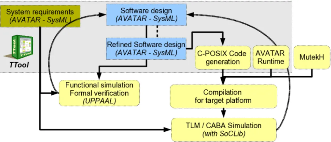
Using the above mentioned tools, our prototyping methodol-ogy is as follows (see Figure 1); all those methodological steps will be further explained in next sections with an automotive-based case study:
1) Requirements. Requirements of the system are first captured with SysML Requirements Diagrams. Require-ments are organized in a tree-based fashion. Both safety and security requirements can be captured.
2) Design. The general structure of the system is modeled with SysML block Diagrams. The behaviour of each block is described with a state machine.
3) Simulation and formal verification. A press-button approach makes it possible to perform simulations with model animation. Safety and security proofs can also be performed directly from the design models without prior knowledge about underlying formal verification techniques. Models can then be modified depending on verification results. Safety and security proofs rely on UPPAAL [6] and on ProVerif [7], respectively.
4) Code generation. The TTool code generator can output C/POSIX code from design models. The generated
ap-plication code can then be compiled along with MutekH using the appropriate kernel configuration and cross-compiler to target a PowerPC based SoCLib platform. 5) Prototyping with SoCLib. The SoCLib simulator can
then be started and the code - generated and compiled during previous step - is loaded and executed like on real hardware. Debugging can be performed at two levels using both the GNU debugger, and simulations traces. Simulations traces can be displayed in TTool during code execution or later. These traces are displayed in the form of sequence diagrams. Models can then be further modified as needed in order to generate a new code. Simulation and formal proofs are meant to be executed during first iterations on the system model. On the contrary, the prototyping of the system is expected to be performed during the last iterations, that is, on more refined models. In all cases (simulation, verification and prototyping), results are directly displayed by TTool in a SysML fashion, therefore facilitating the identification of problems directly on SysML models.
III. CASE STUDY
The AVATAR methodology is illustrated in this paper with an automotive embedded system designed in the scope of the European EVITA project [8]. Recent on-board Intelligent Transport (IT) architectures comprise a very heterogeneous landscape of communication network technologies (e.g., LIN, CAN, MOST, and FlexRay) that interconnect in-car Electronic Control Units (ECUs) [9] [10]. The increasing number of such equipments triggers the development of novel applications that are commonly spread among several ECUs to fulfill their goals.
An automatic braking application serves as a case study [11]. The system works basically as follows: An obstacle is detected by another automotive system which broadcasts that information to neighbor cars. A car receiving such an information has to decide whether it is concerned with this obstacle, or not. This verification includes a plausibility check function that takes into account various parameters, such as the direction and speed of the car, and also information previously received from neighbor cars. Once the decision to brake has been taken, the braking order is forwarded to ECUs responsible for performing the emergency braking. Also, the presence of this obstacle is forwarded to other neighbor cars in case they have not yet received that information.
IV. REQUIREMENT CAPTURE
AVATAR relies on SysML Requirement Diagrams to capture both safety and security related requirements.
A. AVATAR requirement diagrams
In our proposed AVATAR framework, and as explained in one of our previous paper [12], both safety and security re-quirements can be modeled in SysML Requirement Diagrams (RD). In [13], capabilities of SysML diagrams are explored to describe the different aspects of an automotive embedded system such as context, requirement, and behavior of the
system. Different SysML profiles are deployed to support the conceptual stages of the product development life-cycle. For instance, this includes decomposition of system needs and representing them as requirements in the model. The SysML Block Definition Diagram (BDD) is used to manipulate the structure of the system, whereas the system behavior is speci-fied by using Interaction, State Machine and Activity diagrams. Another characteristic of a SysML is: Requirement Con-tainment and Derive Dependency formalisms used to define relationships between requirements. We have more particularly used SysML containment, dependency - deriveReqt, and reuse in different namespaces copy relationships for defining safety and security requirements. As explained in [14], the contain-ment relationship can contain multiple sub-requirements in terms of hierarchy and thus enables a complex requirement to be decomposed into its containing child requirements whereas, deriveReqt determines the multiple derived requirements that support a source requirement. These requirements normally present the next level of requirement hierarchy. A Security Re-quirementstereotype is introduced to make a clear distinction between functional requirements and security requirements of the system. In this way system engineers can model both functional and non-functional requirements of the system in a single modeling environment. Furthermore, a Kind parameter is defined to specify the category of the security requirement such as, confidentiality, access control, integrity, freshness, etc,.
B. Example: security requirements of the case study
We exemplify the use of AVATAR requirements diagrams with security requirements, therefore demonstrating how SysML requirement diagrams have been improved in AVATAR. An EVITA technical report [15] presents all requirements of this case study. In the scope of this paper, only requirements (and properties) related to Denial of Service attacks are presented (see Figure 2). Basically, two main requirements are modeled : PreventBrakeDoSWhenEmergencySituation and PreventBroadcastBrakeDoSWhenEmergencySituation. The security kind of those two requirements is ”Availability”. Those two requirements are themselves composed of sub-requirements, two of which are copied from a requirement named EnsureCorrectDecisionOfEmergencySituation that has been defined in another view. At last, a property named DoSAttackOn CU And CSC Prevention is meant to verify the requirement named BrakeTotalResponseTime.
In this example, requirements are identified in order to further define properties expected to be proved on the system design.
V. DESIGN
Apart from their formal semantics, AVATAR Block and State Machine Diagrams only have a few characteristics which differ from the SysML ones.
Fig. 1. Overall methodology
A. AVATAR design
An AVATAR block defines a list of attributes, methods and signals. Signals can be sent over synchronous or asynchronous channels. Channels are defined using connectors between ports. Those connectors contain a list of signal associations. A block defining a data structure merely contains attributes. On the contrary, a block defined to model a sub-behavior of the system must define an AVATAR State Machine.
AVATAR State Machine Diagrams are built upon SysML State Machines, including hierarchical states. AVATAR State Machines further enhance the SysML ones with temporal operators:
• Delay: af ter(tmin, tmax). It models a variable delay
during which the activity of the block is suspended, waiting for a delay between tmin and tmax to expire. • Complexity: computeF or(tmin, tmax). It models a time
during which the activity of the block actively executes instructions, before transiting to the next state: that com-putation may last from tmin to tmax units of time.
The combination of complexity operators (computeF or()), delay operators, as well as the support of hierarchical states and the possibility to suspend the activity of a substate -endows AVATAR with main features for supporting real-time system schedulability analysis.
B. Designing the active braking application with AVATAR Figure 3 represents the internal block diagram of the active braking use case. This internal block diagram comprises two kinds of blocks:
• Blocks dedicated to the modeling of the environment.
They model messages received via wireless connections, data received from sensors, and data output to actuators. Those blocks are located at the top of the diagram. For instance, the block CarPositionSimulator models the car traffic around the considered automotive system. This
car traffic generates location information to the system. Another example is the GPSSensor that regularly records the car position.
• Blocks dedicated to the modeling of the system itself. Blocks are grouped within a parent block whose name is the one of the modeled ECU. For example, the PTC block models the Power Train Controller ECU. Basically, the system contains four ECUs:
– Communication ECU: It contains three blocks. DSRC Management receives information from the neighbor cars, and can itself broadcast information to neighbor cars. NeighbourhoodTableManagement manages a list of neighbor cars. CorrectnessCheck-inghandles the verification of received messages. – Chassis Safety Controller ECU (CSCU): It also
contains three internal blocks. PlausibilityCheck evaluates whether a given emergency message has to be taken into account. The decision depends not only on the content of the emergency message itself (that is, the nature of the obstacle, whether that obstacle moves or not, etc.), but also on parameters of the car receiving that message: what is the speed of the car, the location of the car with regards to the obstacle, etc. Those information are gathered by the two other blocks: ObjectListManagement and Vehi-cleDynamicsManagement. Finally, either the Plausi-bilityCheck block decides to ignore the emergency message, or to take it into account. In that latter case, an order to brake and reduce the torque of the engine is forwarded to other ECUs, and the emergency is broadcasted, via DSRC Management, to other neighbor cars.
– Bracking Controller ECU (BCU): It contains two blocks: DangerAvoidanceStrategy decides of a given policy to reduce efficiently and safely the vehicle
Fig. 2. Excerpt of the requirement diagram: Denial of Service related security requirements
speed. This policy depends on the degree of emer-gency. The policy might also include the decision to brake. In that latter case, an order to brake is forwarded to the BrakeManagement block.
– Power Train Controller ECU (PTC): It con-tains only one block DrivingPowerReductionStrat-egy which enforces the engine torque modification request.
VI. SIMULATION AND FORMAL VERIFICATION
In TTool, simulations and formal verification can be per-formed from AVATAR models at the push of a button. A. Simulation
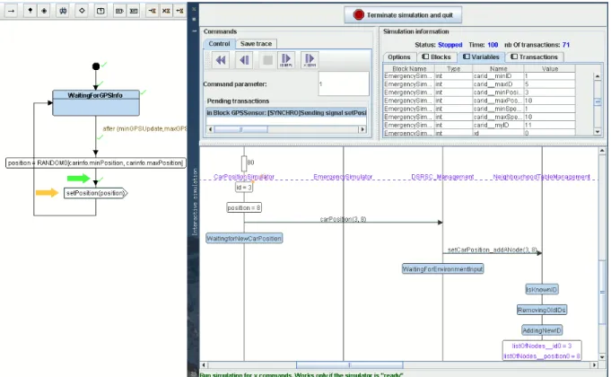
Block instances must be completed with state machine diagrams. Their behavior can therefore be simulated. At sim-ulation step, TTool can draw a sequence diagram represent-ing all actions and communication performed in the system. Additionaly, TTool offers diagram animations, that is, TTool accordingly animates the state machines diagrams with the following information: the last transition being taken, the next possible transitions and all previously taken paths are specifically colored. Usual simulation commands can also be performed from TTool to pilot the simulation trace: reaching
the next breakpoint, step-by-step simulation with transition selection, going back one transition, etc.
Simulation traces display synchronous and asynchronous com-munications between instances, logical actions performed by instances (e.g., variable settings and method calls), and delays between actions or communications. The right side of Figure 4 represents the state machine of the GPSSensor block. The previously executed action is an empty transition, and the sending of the synchronous signal setPosition is enabled. We also know that this is the first time this trace is taken in GPSSensorsince the transition after the sending of the signal has never been taken (no green check next to the transition). On the contrary, previous transitions and actions were already taken in the past since they’ve got that green check on their right. On the right part of the same Figure 4 is displayed the main simulation control window. The top left part of that window is dedicated to actions on the simulation (execute one transaction, go back one transaction, etc.). The top right part is dedicated to information about simulated elements (e.g., value of variables of simulated blocks). At last, the lower part of the figure displays the simulation trace in the form of a sequence diagram. One can notice a delay of 80 units of time followed with two variable settings, and then the sending of
Fig. 3. Block diagram of the Active braking use case
the synchronous signal carPosition, and so on. B. Formal verification
Formal verification generally distinguishes between general properties which can be applied to a large class of systems (e.g., absence of deadlock situations) and properties specific to the system under study.
TTool can formally verify properties using UPPAAL [3]. AVATAR design models are first translated to timed automata that are further provided as input to UPPAAL. In TTool, properties to be verified can be expressed in the following ways:
1) The absence of deadlock can be easily verified by checking a specific option in the formal verification dialog window.
2) Reachability and liveness of given elements of state machine can be evaluated with a simple right-click on those elements. As an example, Figure 5 presents the TTool dialog window when studying the reachability and liveness of the state (EmergencyTakenIntoAccount) defined in the PlausibilityCheck block.
3) A given CTL formulae can be verified directly from TTool. Unfortunately, the CTL formula has to be pro-vided according to the UPPAAL automata corresponding
Fig. 4. Simulation of the active braking automative system
to the AVATAR model. Differently said, an engineer who wants to prove a given CTL formulae has to understand the UPPAAL automata produced by TTool from the SysML models.
4) Observers are blocks which are added to the system design in order to check for given properties. Observers have to be written by hand, and are supposed to be non intrusive on the system. Observers generally contain a specific error state that the observer reaches whenever one of the properties it observes is not satisfied. Using TTool, it therefore suffices to search for the non reach-ability of those error states.
5) SysML diagrams can also be used to formally express system properties. Indeed, we have defined TEPE, a property language settled on SysML parametric dia-grams. TEPE can be used to express properties in terms of logical and temporal relations between system events and attributes [1] [16]. Today, TTool can automatically take into account only basic TEPE properties, and so, complex properties have to be translated by hand into another form, e.g. in CTL or as system observers. TEPE is formally defined with Metric Temporal Logic (MTL) [17] and Fluent Linear Temporal Logic (FLTL) [18], but those two temporal logic remain hidden in TTool.
VII. PROTOTYPING
Again, from an Avatar design model, TTool generates a C/POSIX code at the push of a button. The code can be compiled for the local host, or for the SoCLib platform: in
that latter case, MutekH, the generated code and the AVATAR runtime are compiled and linked against the generated C/POSIX code.
The prototyping phase is intended to be applied on refined models. Indeed, the prototyping phase is particularly useful to evaluate whether a given hardware platform is well suited to execute a given set of software components.
A refined model is a model in which some abstractions of a more abstract model have been resolved. For example, AVATAR designs make it possible to abstract algorithms with their estimated durations: a computeFor(minDuration, maxDuration) can be added to state machines transitions. Another example of abstraction is to let branches of choices undetermined, that is, at a high level of abstraction, all branches of choices may be considered. At formal verification level, this means that all branches have to be explored. But on a more refined model, branches of a choice are not randomly taken, but they are usually rather selected according to the result of operations. Finally, abstractions shall be resolved before doing the prototyping phase. To do so, an AVATAR user could use the AVATAR state machines to put more information in its model. Unfortunately, when coming to complex algorithms - e.g., in our case, cryptographic algorithms - , a graphical model based on state machines is not practical. Therefore, the best option is probably to directly replace given elements of an AVATAR design with its corresponding implementation code, e.g. replacing a computeFor(minDuration, maxDuration) by the C algorithm it models. If this C code included into the model is actually
Fig. 5. Reachability and liveness of the state ”EmergencyTakenIntoAccount” of the block ”PlausibilityCheck”
ignored by the integrated simulation and formal verification capabilities of TTool, this code can be automatically included in the POSIX/C code generated by TTool.
Finally, the most abstract AVATAR models performed with TTool generally represent the control part of applications, and are thus often amenable to simulation and formal verification. On the contrary, more refined models resolve non determinism behaviors with low-level representations (e.g. in C) of data and algorithms. Those refined models are not amenable to simulation and formal verification, but are definitely useful for prototyping purpose.
We now basically explain how TTool generates C/POSIX code from AVATAR designs.
A. Code generation
Basically, the C/POSIX code generator of TTool works as follows:
• One .c and one .h file which contains a representation of the state machine are generated for each block. The trans-lation of operations on variables, method calls and tests is quite straightforward. On the contrary, synchronous data exchange, asynchronous data exchange, and time manipulation are more complex and are thus handled by the AVATAR library (i.e., the AVATAR runtime).
• The main file (main.c) is in charge of defining one thread per block, setting the attributes of those threads (e.g., on which CPU each thread must be executed, which scheduling policy to use, etc.), starting all threads, and finally waiting for their termination.
B. The AVATAR runtime
The AVATAR runtime is a set of libraries that handle all synchronous and asynchronous communications between
blocks. Basically, it relies on data structures to store requests from blocks, and on mutex and condition variables to achieve necessary synchronization between threads of blocks. Its im-plementation is lightweight (about 2000 lines of C code). The AVATAR runtime is automatically linked against the generated code when compiling the latter.
C. Example with the automotive application
The model of the active braking system can be prototyped as described here. The generated source code is usually first prototyped on the local platform. A simple reason for this is that the final hardware target may not yet be available, or even clearly defined. However, when the hardware platform has been specified, the prototyping phase is as follows:
1) Generation of the cross-compiler. A cross-compiler for the target platform must be generated. In our example, we have used gcc-based cross-compilers. In the scope of our example, we have prototyped the active baking application on various 32-bit processor architectures, including PowerPC, Arm, Mips and Sparc.
2) Generation of the C/POSIX code. From an AVATAR model in which non deterministic behaviors have been resolved (ideally), TTool generates a set of .c and .h files, as explained in previous sections. The main file describes how threads are mapped on the different CPUs. 3) Compilation of the code. The generated C code, the AVATAR runtime, and MutekH are compiled with the cross-compiler, and linked together as one executable file. The executable file could obviously be run on the real hardware or a virtual prototyping platform built using SoCLib.
4) Prototyping with SoCLib. The SoCLib simulator is started with the desired hardware configuration which
runs the executable file generated at previous step. Our example has been tested on several processors: PowerPC, which are wildly uses in automotive systems, but also Mips, Arm and Sparc processors. In all cases, we have used a 5 processors: one CPU per ECU, and one CPU to execute the environment blocks.
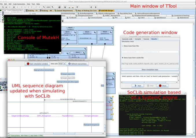
5) Result analysis. Results of the prototyping simulation can be visualized either in the console, or directly in TTool as a UML sequence diagram (see Figure 6). The GNU debugger gdb can also be used to have more information about the execution of the code, e.g., about memory allocations, to perform step-by-step execution, to monitor which threads are currently executing, etc. Using traces, important prototyping information can be obtained. In our case, the latency between the receiving of an emergency message and the corresponding braking action can be clearly evaluated for each processor type.
VIII. RELATED WORK AND DISCUSSION
The contribution presented in this paper is twofold. First, it is based on a SysML-based modeling environment (TTool). Second, the prototyping phase relies on a prototyping platform (SoCLib based) and an embedded operating system (MutekH). A. Modeling and verification environments
Like many other formalized UML-based environments, AVATAR gives a formal semantics to design diagrams, and integrates the possibility to formally express properties with a SysML diagram, a feature usually not supported by other environments. Indeed, the latter commonly rely on formalisms external to UML, e.g., temporal logic formulae, or CCSL in MARTE [19]. The environment presented in [20] offers verification capabilities from UML diagrams captured in the Rhapsody toolkit. But, contrary to AVATAR and TTool, this environment does not support a full engineering process, and in particular, it does not offer any facility for requirement cap-ture or prototyping. Verification takes as input CTL formulae. In TTool, reachability or liveness properties of an action can be verified with a right-click on that action.
The OMEGA environment [21] integrates requirement cap-ture in its methodology and toolkit. Unfortunately, properties can not be easily derived from requirements and used within the verification framework. Both TTool and OMEGA do not support continuous streams. On the contrary, the Artisan toolkit [22] supports them, and also allows for probabilities on transitions, and manages interruptible regions.
The TopCased environment [23] is developed within the Eclipse framework, itself recently enriched with Papyrus [24]. TopCased regroups several model analysis tools and code generators mostly implemented with model transformation techniques. As a whole, TopCased has probably much more functionalities than TTool. the latter is more focused on an engineering process with dedicated third-party tools.
UML/SysML to ESL [25] targets the modeling of System-on-Chips and supports simulations and formal proofs from UML models. Worst case execution times can be computed
as well. But the communication semantic is more limited than in AVATAR. More generally, research on high-level electronic design has led to the definition of several environments: SysML to VHDL-AMS [26] or SysML to Simulink [27]. In mechanics also, SysML is used conjointly with Modelica [28]. Other non-UML environments make it possible to model a system and formally verify it. UPPAAL [3] is a good example of such environments. UPPAAL can indeed model a system in terms of communicating temporal automata. The formal verification of CTL properties is directly embedded into the toolkit. But, UPPAAL can definitely not support a whole engineering process nor it can support the documentation of a project. This remark applies to other formalisms - and their related toolkits - such as Petri nets and the TINA toolkit [29], or LOTOS and the CADP toolkit [30].
B. Prototyping platforms
Prototyping platforms have been proposed at different levels of abstractions.
At a very high-level of abstraction, the DIPLODOCUS/TTool approach [31] targets the design space exploration of System-on-chips. Application functions can be mapped on abstract CPUs or hardware accelerators, and then can be evaluated with simulation [32] or formal verification techniques [33]. How-ever, results that can be expected at that level of abstractions are related to bus or CPU loads, rather than to a precise timing execution on a hardware platform.
SystemC is a widely spread set of C++ libraries and simulation kernel for modeling and implementing electronic systems [34] [35]. Several levels of abstraction have be defined in SystemC, ranging from transactional level modeling to a cycle accurate level modeling. The SoCLib library of component models [4] is based on SystemC. SoCLib supports two levels of abstractions: TLM (Transaction Level Modeling) and CABA (Cycle Accurate Bit Accurate). Other open prototyping plat-forms like SkyEye [36] and QEmu are not based on SystemC components.
C. Embedded operating systems
Multiple operating system projects are available for use as a target POSIX platform for code generation which have different features and memory footprints. As our approach is based on free software projects for modeling or performing simulations and proofs, the operating system running on the target platform had to be free. This thus rules out VxWorks and similar proprietary operating systems from the scope of our demonstration even if the use of such software is technically possible in our toolchain. The SoCLib prototyping platform has a number of supported operating systems, including UNIX like implementations such as NetBSD as well as some lightweight embedded operating systems.
NetBSD and various Linux flavors are system-call based and require a separate set of user library packages in order to build and run applications. System start-up of such large operating
Fig. 6. Prototyping environment based on TTool, MutekH, and SoCLib
system kernels running on top of a SystemC simulator may require a large amount of time.
Most embedded operating systems can be used without system-call interfaces, the application is thus compiled along with the kernel and all objects files are linked in a monolithic binary file. Some well known operating systems based on this approach include FreeRTOS, eCos and RTEMS. eCos and RTEMS may suit our needs because of their support in SoCLib, and their implementation of the thread POSIX interface. We expect to support them in the future. The operating system chosen in the scope of our study is MutekH. It offers similar features: it’s highly configurable and comes with suitable libraries, and with the additional benefit of heterogeneous multiprocessors support and a better SoCLib integration.
Moreover, when used along with the SoCLib platform, MutekH can be configured to provide necessary information related to memory allocation and execution stack boundaries to the MemoryChecker SoCLib module. This information along with details of memory accesses performed by the processors allow this module to track suspicious memory access and report them to the developer. This feature is of great help on hardware were no Memory Management Units can be used which prevents relying on memory protection to find bugs or undersized stacks [37]. Those debugging features apply to both operating system and user codes. In our approach, the
user code refers both to the generated code and also to the C code directly provided by the user as design model parameters.
IX. CONCLUSIONS AND FUTURE WORK
The combination of AVATAR/SysML/TTool and SoCLib/-MutekH offers an integrated platform for embededd systems engineering and prototyping. Indeed, this platform offers at the same time a well-known modeling language (UML, SysML), an easy-to-use proof environment and a prototyping simulation platform comprising several commonly used microprocessors and operating systems. Simulation, proofs and prototyping can be performed at the push of a button and their results are displayed directly in the model. The paper presents the whole AVATAR methodology and illustrates the contribution with an active braking automotive application. In particular, the formal validation phase demonstrates that emergency messages may result in automatic braking actions. Additionaly, the proto-typing phase enables an accurate evaluation of the latency between an emergency message and the braking of the car, taking into account hardware components used in the target platforms.
Our future work intends to apply this methodology to a wider set of embedded systems, including aeronautics plat-forms.
REFERENCES
[1] D. Knorreck, L. Apvrille, and P. De Saqui-Sannes, “Tepe: A sysml lan-guage for time-constrained property modeling and formal verification,” ACM SIGSOFT Software Engineering Notes, vol. 36, no. 1, pp. 1–8, Jan. 2011.
[2] L. Apvrille, “Webpage of TTool,” in http://ttool.telecom-paristech.fr/, 2011.
[3] J. Bengtsson and W. Yi., “Timed automata: Semantics, algorithms and tools,” in Lecture Notes on Concurrency and Petri Nets. W. Reisig and G. Rozenberg (eds.), LNCS 3098, Springer-Verlag, 2004, pp. 87–124. [4] SoCLib, “SoCLib: an open platform for virtual prototyping of
multi-processors system on chip (webpage),” in http://www.soclib.fr, 2010. [5] LIP6, “Mutekh,” http://www.mutekh.org.
[6] J. Bengtsson and W. Yi., “Timed automata: Semantics, algorithms and tools,” in Lecture Notes on Concurrency and Petri Nets. W. Reisig and G. Rozenberg (eds.), LNCS 3098, Springer-Verlag, 2004.
[7] B. Blanchet, “Automatic verification of correspondences for security protocols,” Journal of Computer Security, vol. 17, no. 4, pp. 363–434, Jul. 2009.
[8] EVITA, “E-safety Vehicle InTrusion protected Applications,” http://www.evita-project.org/.
[9] H. Seudi´e, J. Shokrollahi, B. Weyl, A. Keil, M. Wolf, F. Zweers, T. Gen-drullis, M. S. Idrees, Y. Roudier, H. Schweppe, H. Platzdasch, R. E. Khayari, O. Henniger, D. Scheuermann, L. Apvrille, and G. Pedroza, “Secure on-board architecture specification,” EVITA Project, Tech. Rep. Deliverable D3.2, 2010.
[10] H. Schweppe, M. S. Idrees, Y. Roudier, B. Weyl, R. E. Khayari, O. Henniger, D. Scheuermann, G. Pedroza, L. Apvrille, H. Seudi´e, H. Platzdasch, and M. Sall, “Secure on-board protocols specification,” EVITA Project, Tech. Rep. Deliverable D3.3, 2010.
[11] E. Kelling, M. Friedewald, T. Leimbach, M. Menzel, P. Sger, H. Seudi, and B. Weyl, “Specification and evaluation of e-security relevant use cases,” EVITA Project, Tech. Rep. Deliverable D2.1, 2009.
[12] M. Idrees, Y. Roudier, and L. Apvrille, “A framework towards the efficient identification and modelling of security requirements,” in 5`eme Conf. sur la S´ecurit´e des Architectures R´eseaux et Syst`emes d’Information (SAR-SSI 2010), Menton, France, May 2010.
[13] L. Balmeli, “An overview of the systems modeling language for product and systems development - part 1 requirements, use-case, and test-case modeling,” T.J. Watson Research Center and Tokyo Research Laboratory, IBM, Software Group, Tech. Rep., 2006.
[14] O. M. G. OMG, “SysML,” in http://www.sysml.org/, 2011.
[15] A. Ruddle, D. Ward, B. Weyl, S. Idrees, Y. Roudier, M. Friedewald, T. Leimbach, A. Fuchs, S. G¨urgens, O. Henniger, R. Rieke, M. Ritscher, H. Broberg, L. Apvrille, R. Pacalet, and G. Pedroza, “Security require-ments for automotive on-board networks based on dark-side scenarios,” EVITA Project, Tech. Rep. Deliverable D2.3, 2009.
[16] D. Knorreck, “Uml-based design space exploration, fast simulation and static analysis,” Ph.D. dissertation, Telecom ParisTech, EDITE, Oct. 2011.
[17] R. Koymans, Specifying Message Passing and Time-Critical Systems with Temporal Logic. Secaucus, NJ, USA: Springer-Verlag New York, Inc., 1992.
[18] E. Letier, J. Kramer, J. Magee, and S. Uchitel, “Fluent temporal logic for discrete-time event-based models,” in Proceedings of the 10th European software engineering conference, ser. ESEC/FSE-13. New York, NY, USA: ACM, 2005, pp. 70–79.
[19] F. Mallet, J. DeAntoni, C. Andr´e, and R. de Simone, “The clock constraint specification language for building timed causality models,” Innovations in Systems and Software Engineering, vol. 6, pp. 99–106, 2010, 10.1007/s11334-009-0109-0. [Online]. Available: http://dx.doi.org/10.1007/s11334-009-0109-0
[20] E. C. da Silva and E. Villani, “Integrating sysml and model-checking techniques for the v&v of space-based embedded critical software (in portugese),” in Brasilian Symposium on Aeropspace Engineering and Applications, 2009.
[21] I. Ober and I. Dragomir, “Omega2: A new version of the profile and the tools,” in 14th IEEE International Conference on Engineering of Complex Computer Systems, UML-AADL’2009, Potsdam, 2009, pp. 373–378.
[22] Atego, “Artisan studio,” http://www.atego.com/products/artisan-studio/. [23] P. Farail, P. Gaufillet, A. Canal, C. L. Camus, D. Sciamma, P. Michel,
X. Crgut, and M. Pantel, “The topcased project: a toolkit in open source
for critical aeronautic systems design,” in In ERTS2006: Embedded Real Time Software, Toulouse, France, Nov. 2006.
[24] CEA, “Papyrus,” http://www.papyrusuml.org.
[25] A. Vielhl, T. Schonwald, O. Bringmann, and W. Rosenstiel, “Formal performance analysis and simulation of UML/sysML models for ESL design,” in DATE ’06: Proceedings of the conference on Design, automation and test in Europe, Munich Germany, 2006, pp. 1–6. [26] RealTime-at-Work, “Sysml-companion: Virtual prototyping from sysml
models,” in http://www.realtimeatwork.com/software/sysml-companion/, 2011.
[27] Y. Vanderperren and W. Dehaene, “From UML/SysML to Mat-lab/Simulink: current state and future perspectives,” in DATE’06: Pro-ceedings of the conference on Design, automation and test in Europe. 3001 Leuven, Belgium, Belgium: European Design and Automation Association, 2006, pp. 93–93.
[28] C. J. Paredis, Y. Bernard, R. M. Burkhart, H.-P. de Koning, S. Frieden-thal, P. Fritzson, N. F. Rouquette, and W. Schamai, “An overview of the sysml-modelica transformation specification,” in INCOSE’2010, 2010. [29] B. Berthomieu and F. Vernadat, “Time petri nets analysis with tina,” in
3rd Int. IEEE Conf. on The Quantitative Evaluation of Systems (QEST 2006), 2006, pp. 123–124.
[30] “The CADP toolkit,” http://www.inrialpes.fr/vasy/cadp.
[31] L. Apvrille, W. Muhammad, R. Ameur-Boulifa, S. Coudert, and R. Pacalet, “A UML-based Environment for System Design Space Ex-ploration,” 13th IEEE International Conference on Electronics, Circuits and Systems, 2006. ICECS 06, pp. 1272–1275, 2006.
[32] D. Knorreck, L. Apvrille, and R. Pacalet, “Fast simulation techniques for design space exploration,” in 47th International Conference Objects, Models, Components, Patterns, vol. 33, Zurich, Switzerland, Jun. 2009, pp. 308–327.
[33] ——, “Formal system-level design space exploration,” in The 10th annual international conference on New Technologies of Distributed Systems (NOTERE’2010),. Tozeur, Tunisie: IEEE, Jun. 2010. [34] T. Grotker, System Design with SystemC. Norwell, MA, USA: Kluwer
Academic Publishers, 2002.
[35] W. Mueller, J. Ruf, D. Hoffmann, J. Gerlach, T. Kropf, and W. Rosen-stiehl, “The simulation semantics of systemc,” in In Proc. of DATE 2001. IEEE CS. Press, 2001, pp. 64–70.
[36] SkyEye, “Webpage of SkyEye,” in www.skyeye.org/, 2011.
[37] N. Pouillon, A. Becoulet, A. V. D. Mello, F. Pecheux, and A. Greiner, “A generic instruction set simulator api for timed and untimed simulation and debug of mp2-socs,” in In IEEE Proc. of Rapid System Prototyping 2009. Paris, France: IEEE, 2009, p. 116?122.