an author's
http://oatao.univ-toulouse.fr/21553
https://doi.org/10.1016/j.engstruct.2018.06.026
Frigui, Farouk Omar and Faye, Jean-Pierre and Martin, Carmen and Dalverny, Olivier and Pérès, François and
Judenherc, Sébastien Global methodology for damage detection and localization in civil engineering structures.
(2018) Engineering Structures, 171. 686-695. ISSN 0141-0296
Global methodology for damage detection and localization in civil
engineering structures
F. Frigui
a,b,⁎, J.P. Faye
a, C. Martin
a, O. Dalverny
a, F. Peres
a, S. Judenherc
baLaboratoire Génie de Production (LGP), INP-ENIT, Univ. de Toulouse, Tarbes, France bSTANEO SAS, 2, rue Marcel Langer, 31600 Seysses, France
Keywords: Automated SHM Damage detection Damage localization Dynamic behaviour analysis
A B S T R A C T
The Structural Health Monitoring (SHM) in civil engineering faces several challenges. The main issue lies in defining a reliable and precise methodology of damage detection and localization in order to allow preventive maintenance or to enable the definition of repair actions. In this paper, a new methodology of SHM is proposed. Using Vibration-Based Damage Detection Methods (VBDDM), a damage detection and localization algorithm is elaborated and tested on a Finite Element Model (FEM) of an existing building. In a first case, the damage is introduced artificially by a local reduction of stiffness, while in the second case, the damage is calculated ac-cording to a real seismic signal from the italian L’Aquila earthquake. The advantages and disadvantages of each dynamic monitoring technique are discussed and the usefulness of the algorithm is highlighted.
1. Introduction
The monitoring and the assessment of structures, in order to ensure human and material safety, is a very important issue in civil en-gineering. There are several methods to evaluate the damage such as radiography, ultrasound or dynamic behaviour analysis. These techni-ques are called non-destructive methods or SHM technitechni-ques. The identification of the damage can be classified into 4 levels: Level 1: Detection of the damage, level 2: Localization of the damage, level 3: Quantification of the damage and level 4: Evolution of the damage[1]. SHM methods can be subdivided into two groups: local and global methods. Local methods concern small structures, and are mainly ap-plied in the aeronautics and automotive fields. They are very efficient and very expensive[2]. Whereas, global methods concern large struc-tures and are based on the study of their dynamic behaviour. They are also called Vibration-Based Damage Detection Methods (VBDDM)[3,4]. Methods used in civil engineering are usually global methods[5]. When structures are damaged, their rigidity decreases as their damping in-creases. This results in a modification of the dynamic characteristics such as reduction of eigenfrequencies and modification of mode shapes. These changes are related to a modification in the physical properties. Thus, the monitoring of the dynamic characteristics of a structure be-tween an initial state (undamaged state) and a final state (damaged state), represents a method of performance evaluation. This includes mostly the eigenfrequencies method (level 1), the Modal Assurance
Criterion (MAC) (level 1), the Mode Shape Curvature (MSCM) method (level 2), the Curvature Damage Factor (CDF) (level 2) and the flex-ibility method (level 2)[6,7]. Nonetheless, these techniques have sev-eral limitations. Over the last few years, the main issue has been the definition of a complete and precise monitoring methodology. Several studies worked on developing better sensors, improving signal-proces-sing, applying existing techniques or developing new techniques[8]. However, the problem still lies in obtaining a good identification of dynamic characteristics and accurate correlation between their varia-tions, the appearance of the damage and its location. This article pre-sents a new methodology that simplifies the monitoring of civil en-gineering structures based on the methods mentioned above. By applying these methods following a precise order and taking into ac-count the sensitivity, the simplicity and the SHM level of each method, a new detection and localization algorithm is defined. The goal of de-fining such an algorithm is to facilitate the implementation and in-tegration of SHM techniques into permanent and independent mon-itoring system. The algorithm is evaluated on a numerical model of an existing building. The considered model is the 18-story Ophite tower located in Lourdes, France. The tower is permanently instrumented with 24-channel system and an acquisition station[9]. The numerical model was calibrated using the modal parameters (eigen frequencies, modes shapes and damping) identified in previous works[10]. Two cases of damage are considered. In the first case, the damage is in-troduced in the numerical model artificially by a local reduction of
⁎Corresponding author at: Laboratoire Génie de Production (LGP), INP-ENIT, Univ. de Toulouse, Tarbes, France.
E-mail addresses: ff[email protected] (F. Frigui), [email protected] (J.P. Faye), [email protected] (C. Martin), [email protected] (O. Dalverny), [email protected] (F. Peres), [email protected] (S. Judenherc).
= − f f f ∆ iu i d (1) with f denotes the eigenfrequency, i denotes theith mode, u the
un-damaged state and d the un-damaged state. Variations of the eigen-frequencies depend on the position of the damage and its severity. In fact, the more severe the damage is, the greater the frequency drop is. For some modes, the damage placed on maxima of the mode shape curvature will produce the highest variations while, damage placed on inflection points of the mode shape curvature will not produce varia-tions in eigenfrequency. For other locavaria-tions of damage, the frequency shift will be proportional with the mode shape curvature of the vibra-tion mode at that locavibra-tion[15]. In real life situations, the major dis-advantage of this method is that damages are detected only when the shift of frequencies is of 5% or more. Shifts lower than 5% can be ex-plained by phenomena not related to any damage such as hygrothermal effects [16]. The MAC method may be an alternative since it uses spacial informations (i.e. the mode shapes).
2.1.2. Modal Assurance Criterion (MAC) method
The MAC method is based on the comparison of two measurement series in order to define the correlation between them[17]. The mode shapes are affected by damages and their variations denote the presence of an anomaly in the structure. Thus, by applying the MAC criterion on the mode shapes of healthy and damaged structure, damages are de-tected in case of an incomplete correlation between them [18]. The MAC criterion is a matrix defined by Eq.(2)and the value of its com-ponent varies between 0 and 1.MACjk takes the value 1 if the
corre-lation is complete and takes the value 0 if there is no correcorre-lation at all. In this matrix, the most interesting values are those of the diagonal. They reflect the correlation between the mode shapes of the same mode. Any diagonal value less than 1 can be interpreted as a damage indication[19]. = ∑ ∑ = = MAC ψ ψ ψ ψ , ( [ ] [ ] ) ([ ] ) ([ ] ) j k i n u i j d ik i n u i j d ik 1 2 1 2 2 (2) where[ ]ψu and[ ]ψd denote respectively the mode shapes of the
un-damaged and the un-damaged structure.MAC ,j kfactor indicates the degree
of correlation between thejthand thekthmode and n is the number of
measurement nodes.
For low severity damage, corresponding to eigenfrequencies shift less than 5%, the MAC method indicates damage in higher order modes. These modes are more sensitive to the damage and are difficult to identify in real life situations[20]. Moreover, experimentally, in the case of two series of measurements on the same structure’s state, the estimation of the mode shapes is not precise and the correlation is not complete. Several methods of Operational Modal Analysis (OMA) exist and allow the experimental identification of mode shapes such as Fre-quency Domain Decomposition (FDD) algorithm[21]. In the literature, the FDD algorithm is applied around a resonance peak in the Power Spectral Density (PSD) that represents an eigenfrequency. The mode shape is therefore calculated around this peak and MAC is used as a comparison criterion with mode shape computed from the analytical model. It is admitted that a good identification of mode shape is given for any diagonal value greater than 0.8 around the peak. This limit value is called the MAC rejection level[22]. Therefore, it would be necessary for the diagonal values to be less than 0.8 for damage to be detected with confidence.
2.2. Damage localization methods
2.2.1. Mode Shape Curvature Method (MSCM)
This technique is based on the relationship between the mode shape curvatures and the flexural stiffness.
″ =
ψ x M x
EI
( ) ( )
(3) whereψ x″( )denotes the mode shape curvature at locationx M x, ( )is the bending moment and EI is the flexural rigidity. According to Eq.(3), it can be seen that when the structure is damaged, its Young’s modulus varies inducing a variation of the mode shape curvatures[7]. MSCM may be defined as the absolute difference in curvatures of the un-damaged and the un-damaged state. It is computed as follows[23]:
″ = ″ − ″
ψ ψ ψ
∆ i | i u, i d, | (4)
withψi″denotes the mode shape curvature vector of theithmode, u and
d denote respectively the healthy and the damaged structure. It is ad-mitted that the local increase in the curvature occurs when the stiffness is locally reduced (i.e. local damage)[24]. Curvatures can be computed using the central-difference formulas[25]:
″ = + − + − ψ ψ ψ ψ h 2 i j i j i j i j , 1, , 1, 2 (5)
where h is a constant distance that separates two consecutive nodes
[26].ψi j, is the mode shape component of theithcoordinate at the jth
mode.
2.2.2. Curvature Damage Factor (CDF)
CDF method is derived from MSCM. The main idea of this technique is to average the variations of mode shape curvatures at a given co-ordinate j with respect to the number of considered modes. The use of several modes enables the detection of damages affecting mode shapes other than that of the fundamental mode and reduces the weight of misleading informations[27]. This method is computed as follows:
= ∑= ″ − ″ CDF ψ ψ N | | i N i j u i j d 1 , , (6) where N is the total number of modes.
The accuracy of detection and localization depends on the number of measurement nodes. In other words, the more complete the de-scription of the mode shape is, the more accurate the localization of the damaged area is[28].
2.2.3. Flexibility method
The presence of damage induces stiffness decrease and flexibility Young’s modulus (first scenario: 50% of local reduction, second
sce-nario: 25% of local reduction). In the second case, the damage is in-troduced by a true seismic signal in a nonlinear structural finite element model of the Ophite tower. The purpose of this algorithm is to locate the damaged floor.
2. Damage detection and localization methods
Here in, we present the detection and localization methods. These techniques are usually applied separately according to desired SHM level. This list is not exhaustive but it represents methods commonly used in civil engineering. The implementation, advantages and dis-advantages of each method are detailed.
2.1. Damage detection methods 2.1.1. Eigenfrequencies method
During the damaging event, the physical properties of a structure undergo a change inducing a modification of the modal characteristics, particularly, a fall of the eigenfrequencies [11]. Thus, the monitoring of the eigenfrequencies presents a simple method of SHM of mechanical and civil engineering structure [12]. It is easy to implement and is very sensitive to the damage [6]. Widely used, it reflects the behaviour of the
structure in its entirety and only satisfies the first level of SHM since no indication of the sensors position is required for its implementation
∑
= = F ω ψ ψ 1 i N i i i t 1 2 (7) The main idea is to compare flexibility matrices of the undamaged and the damaged state:= −
F F F
∆ u d (8)
Whereψidenotes theithmode shape,ωiis theitheigenfrequency and N
is the number of modes.
Given that the flexibility matrix is inversely proportional to the square of the eigenfrequencies, this matrix converges rapidly with lower modes. Therefore, a good estimation of the flexibility matrix can be established with few lower modes. Generally, the first two modes are sufficient[30]. Each column of∆F corresponds to a measurement lo-cation. The damage location is deduced from the maximum absolute value of each columnγj [6]:
=
γj max |∆ |F
i ij (9)
with j denotes the measuring point coordinate. The main disadvantage of localization methods is that precise results require the fullest iden-tification possible of mode shapes (i.e. a large number of sensors) and the interpretation of results requires knowledge of the boundary con-ditions[31,32].
3. Algorithm of damage detection and localization
One of the most important issues in structural health monitoring in civil engineering is the definition of a global methodology allowing accurate detection and localization of damages and its integration into an independent monitoring system[33]. Today, there is still no efficient method to satisfy certain requirements such as: precise detection, pre-cise localization and ease of implementation. Despite the fact that they have several limitations, the methods mentioned in the previous section are found to be complementary. That is to say that, by applying these methods in a particular order and by taking into account the SHM level, the computation complexity and the detection and localization condi-tions, it would be possible to detect and to locate structural damages with accuracy. It’s on this terms that we propose a new detection and localization algorithm (Fig. 1).
This algorithm is divided into two levels: a detection level and a localization level. In the detection level, the eigenfrequency method is applied in the first place for its simplicity and sensitivity. The damage is detected for all variations greater than 5%, in which case, the locali-zation phase is applied. Otherwise, the MAC method is applied. A value lower than0.8in the diagonal of the MAC matrix, indicates the presence of damage. In which case, the localization phase is applied. Otherwise, it would be necessary to increase the number of modes. If higher modes are already used and the detection conditions are not satisfied, then the structure is healthy. In the localization phase, CDF, MSCM and flex-ibility method are applied. Since each method is sensitive to boundary conditions, the position of the damage and its severity, the application of several methods in the localization phase makes it possible to im-prove the accuracy of localization. If results are scattered or if the variations are null, the number of modes should be increased. Generally localization results are accurate using the first two modes. In order to apply the algorithm, the distance between the measurement nodes, as well as eigenfrequencies and mode shapes of both healthy and damaged state are needed. In real life situations, the dynamic parameters can be identified using Operational Modal Analysis (OMA) techniques: Eigenfrequencies can be identified through the Stochastic Subspace Identification (SSI) method [34]and mode shapes through the FDD
method. The algorithm was developed using MATLAB software.
4. Applications of the damage detection and localization algorithm
The building considered in this study is the Ophite Tower (Fig. 2a), located in Lourdes, France. It is a reinforced concrete structure com-posed of 18 storeys, each floor is 2.5 m tall. It was built in 1972 and it is permanently instrumented with 24-channel system and an acquisition station. The building dimensions are: 24 m × 18 m × 50 m. Its external appearance shows no crack. In this work, we used the numerical model of the Ophite tower (Fig. 2b). The model is realized with Abaqus soft-ware. In order to have a reliable model and therefore to obtain con-sistent results in comparison with the experimental identification re-sults, The modulus of elasticity used corresponds to that of an old reinforced concrete (E=19.7 GPa) [10,35]. The elastic bending, twisting, and fluctuating forces on the structure that may be caused by wind forces, were not taken into account in the numerical simulation. Generally, conventional seismic analysis practice do not take into account the flexibility of the foundation and adjacent soil and as a consequence, the evaluated seismic performance may be significantly different from that of the actual buildings[36]. Since the purpose of this study is to define the state of health of the structure, the soil-structure interaction has not been taken into account during numerical modelling.
4.1. Sensor locations
To detect the damaged floor, at least one information at each floor must be extracted. Given that the structure is composed of 18 storeys, which are 2.5 m tall each, we considered 18 nodes. The positioning of the measurement nodes in the numerical model is different from that of the sensors currently installed in the building. We decided to have one measurement node per floor in order to describe the mode shapes of the structure in the most faithful way possible, to optimize the number of sensors that could be placed and to detect the damaged level. The nodes are equidistant and aligned, allowing a simple calculation of the mode shape curvature method. The distance between two consecutive nodes is of 2.5 m. Given that the minimum number of modes necessary for applying the CDF method and for approximating the flexibility matrix is two, the first two bending modes in the →y direction are used.
Fig. 1. Algorithm of damage detection and localization.
increase. Thus, the monitoring of the flexibility matrix can be con-sidered as a damage indicator. Under the condition of a mass normal-ization of mode shapes (ψMψt= 1), flexibility matrix can be computed
Experimentally, these two modes can be identified using single-axis sensors.
4.2. Artificial damage
Two scenarios of artificial and local damage are considered:
•
First scenario: a single floor damage, equivalent to a 50% reduction in the Young’s modulus.•
Second scenario: a single floor damage, equivalent to a 25% re-duction in the Young’s modulus.The purpose is to evaluate the performance of the algorithm and to place emphasis on the conjunction of the SHM methods, in the case of severe damage and low damage.
4.2.1. First scenario
The damage is introduced at the 8th floor (between node 7 and 9) and having the properties of weakened reinforced concrete (Fig. 3): the Young’s modulus is of 9 GPa, representing about50%reduction of that of an old reinforced concrete. This reduction corresponds to the elastic modulus reduction of reinforced concrete exposed to fire[37]. The ei-genfrequencies (Table 1) and the mode shapes (Fig. 4) were extracted from the Abaqus software.
Using the eigenfrequency method, the damage was detected thanks to a reduction of5.18%in the first bending mode (which is higher than
5%). At this stage, the algorithm detected the damage and MAC method was not triggered. For the localization level, significant variations in the mode shape curvatures have been noted. These variations were located between node 7 and 9 for the first mode (Fig. 5a), and around the node 9 for the second mode (Fig. 5b). Variations were also observed using the CDF between node 7 and 9 (Fig. 6).
In our case study, the structure is embedded at its base. Therefore, its flexibility increases towards the free end. When the structure is damaged, the flexibility increases particularly in the damaged area. Thus, by applying the flexibility method, the damage is localized at the maximum local increase of flexibility. To detect local increase we in-troduced the damage indexγj jL+
, 1, using Eq.(9), as follows:
= −
+ +
γj jL γ γ
j j
, 1 1 (10)
where the damage is deduced from the maximum values ofγj jL+
, 1.
InFig. 7a, we noticed sharp increase in flexibility between the nodes 7 and 9. This variation was highlighted inFig. 7b in which, a maximum variation was noted between the node 8 and 9. Since the algorithm is automated, the locations of most important variations were displayed
Fig. 2. The Ophite tower: (a) street view, (b) the numerical model.
Fig. 3. Damaged building at the 8th floor by reduction of Young’s modulus. 18 measuring nodes are positioned equidistantly in the middle of each floor. Table 1
Shifts of the eigenfrequencies after the local damage. fu[Hz]
fd[Hz] Frequency shift [%]
1st bending mode 1.74 1.65 5.18
as follows:
•
Damage is detected around node 7 using MSCM - mode 1/ Check the 7th floor.•
Damage is detected around node 9 using MSCM - mode 2/ Check the 9th floor.•
Damage is detected around node 9 using CDF/ Check the 9th floor.•
Damage is detected around node 8 and 9 using flexibility method/ Check the 8th and the 9th floor.4.2.2. Second scenario
In the second scenario, the damage was introduced at the same storey (the 8th floor) by a local reduction of25%of the elastic modulus (E=14.77GPa). In this case, the variation of eigenfrequencies was less than5%. The damage was detected thanks to the MAC method (Fig. 8). In fact, the correlation of mode shapes at the 16th mode was not complete which corresponds toMAC16,16=0.7(a value less than0.8).
Using the first two bending modes, the damage was localized around the nodes 7 and 9. Indeed, it was found that the most important variations of the mode shape curvatures (Fig. 9) and their averages (CDF) (Fig. 10) were localized around the nodes 7 and 9. A significant increase of flexibility was noticed between nodes 7 and 8 and nodes 8 and 9 (Fig. 11a). This local increase is highlighted thanks to the damage indexγL(Fig. 11b).
Results displayed from the algorithm were:
•
Damage is detected around node 7 using MSCM - mode 1/ Check the 7th floor.•
Damage is detected around node 8 using MSCM - mode 2/ Check the 8th floor.•
Damage is detected around node 9 using CDF/ Check the 9th floor.•
Damage is detected around node 7 and 8 using flexibility method/ Check the 7th and the 8th floor.Fig. 4. The first two bending mode shapes: undamaged structure (a), damaged structure (b)-first scenario.
Fig. 5. Mode shape curvature method: (a) 1st bending mode, (b) 2nd bending mode-first scenario.
Fig. 6. Curvature Damage Factor using the first two bending modes-first sce-nario.
In this first simulation, the complementarity of first-level methods has been emphasized and the damage was detected and localized in both cases: weak and severe damage. In order to evaluate the
performance of the algorithm in the case of several structural damages we decided to damage the structure with a real seismic signal. The FEM, the seismic load, the simulation results, and the algorithm results are detailed in the following section.
4.3. Damage by seismic signal
The 2009 L’Aquila earthquake occurred in the Abruzzo region in central Italy. Its magnitude rises to 6.3 on the moment magnitude scale. Its epicenter was near L’aquila, the capital of Abruzzo region. The ca-pital and the surrounding villages suffered the most damage. The
Fig. 7. Flexibility method: (a) flexibility variation along the structure, (b) damage index-first scenario.
Fig. 8. Modal Assurance criterion.
Fig. 9. Mode shape curvature method: (a) 1st mode, (b) 2nd mode.
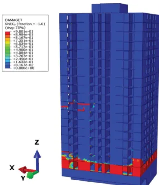
earthquake damaged about 10,000 buildings. Many buildings have also collapsed[38]making this earthquake the deadliest in Italy. The L’A-quila earthquake accelerogram is used in this third numerical simula-tion test (Fig. 12). The likelihood that such an earthquake occurs in Lourdes is out of scope. The purpose being to damage the structure, only 10 s of the signal are used to excite the model in the→y direction. The numerical model takes into account the complex and non-linear behaviour of concrete. The recognition of crack patterns is made through the elasto-plastic damage model: Concrete Damage Plasticity (CDP)[35]. This model is governed by the following equation:
= − −
σ (1 d D) el: (ε εpl)
0 (11)
whereσ is Cauchy stresse tensor, d the scalar stiffness degradation variable, ε the strain tensor,εpl the plastic strain tensor and Del
0 the
undamaged elastic stiffness of the material.
After the seismic event, the model is found to be substantially da-maged in the 1st and 8th storey. These damages represent a typical damage pattern of reinforced concrete: first floor failure and mid-floor failure[39]. The most important damage in the building was that of the 1st floor (seeFig. 13).
We considered the same 18 measurement nodes as we have pre-viously chosen (Fig. 3). Only the first two bending modes in the→y di-rection are used. The eigenfrequencies (Table 2) and the mode shapes (Fig. 14) were extracted from Abaqus software.
The seismic signal of L’Aquila earthquake caused degradation of structural stiffness and an important drop of the first bending fre-quency. Damages were detected thanks to a reduction of 10.63% in the first bending mode frequency (Table 2). For the localization level, sig-nificant variations in the mode shape curvatures have been noted. They were located between node 1 and 2 for the 1st mode (Fig. 15(a)). Less
important variations were noticed at node 4 and 5. For the 2nd mode, significant variations were abserved between node 1 and 2 (Fig. 15(b)). In order to reduce misleading information and to summarize the results for all used modes, the CDF method was applied, in which case, var-iations were also noted between node 1 and 2 (Fig. 16).
A sharp increase in flexibility between the node 7 and 9 was noticed inFig. 17a and highlighted inFig. 17b by applying the damage index. Using flexibility changes, the damage in the first floor was not detected. This can be explained as follows: Letζjbe the maximum value of each
column j ofFu(the undamaged state) (ieζj=max | |i uF ).Fig. 18shows
the evolution of flexibility (ζj) along the measurement nodes. Since the first floor is close to the embedded part of the building, its flexibility
Fig. 11. Flexibility method: (a) flexibility variation along the structure, (b) damage index-second scenario.
Fig. 12. Vertical acceleration recorded at station AQV for 2009 L’Aquila earthquake (http://www.strongmotioncenter.org/).
Fig. 13. Tensile damage of the Ophite tower numerical model during L’aquila earthquake.
Table 2
Shifts of the eigenfrequencies after the seismic event.
fu[Hz] fd[Hz] Frequency shift [%]
1st bending mode 1.74 1.55 10.63
was quite low. Thus the variation of the flexibility matrix was also weak and the damage in the 1st floor was not identified.
In conclusion, the detected damages were around node 1 and 2 (1st and 2nd floor) and node 7 and 8 (7th and 8th floor). Results displayed from the algorithm were:
•
Damage is detected around node 2 using MSCM - mode 1/ Check the 2nd floor.•
Damage is detected around node 2 using MSCM - mode 2/ Check the 2nd floor.•
Damage is detected around node 2 using CDF/ Check the 2th floor.•
Damage is detected around node 7 and 8 using flexibility method/ Check the 7th and the 8th floor.In this third simulation, the complementarity of second-level methods has been emphasized and floors surrounding the damages were detected and localized.
5. Conclusions
In this study we’ve developed a new algorithm of damage detection and localization on civil engineering structures. The method is based on traditional techniques like eigenfrequencies method, MAC, MSCM, CDF and flexibility method. Our goal is to propose a simple way to monitor civil engineering structures allowing a clear improvement for SHM. The study carried out allows us to highlight the following conclusions:
•
The proposed algorithm is able to detect and localize damages using several SHM techniques in an automatic way.•
It would facilitate and accelerate the definition of repair actions and optimize maintenance expenses.•
Numerical results show a good performance of the algorithm in the first artificial damage scenario (50% reduction of the Young’s modulus).•
In the case of less severe damage (second artificial damage, 25%Fig. 14. The first two bending mode shapes: undamaged structure (a), damaged structure (b)-damage by seismic signal.
Fig. 15. Mode shape curvature method: (a) 1st bending mode, (b) 2nd bending mode-damage by seismic signal.
Fig. 16. Curvature Damage Factor using the first two bending modes-damage by seismic signal.
reduction of the Young’s modulus), the variation of the eigen-frequencies was very small and the damage was detected by the MAC method at the 16th mode. In a real life situation, this mode is difficult to identify, and the frequency variations found in the lower modes are small and difficult to interpret. The detection conditions are based on what has been reported in the bibliography: a variation greater than 5% of eigenfrequencies or a correlation of mode shapes less than 0.8 are necessary for damage to be detected with con-fidence. Additional studies are needed to properly define these limits according to the nature of the structure, its age and its boundary conditions, in order to dissociate variations due to da-mages and variations due to hygrothermal effects.
•
In the case of multiple damages resulting from a seismic loading, the complementarity between the localization techniques is highlighted. By applying several methods, damages have been indeed localized.Further studies need to be conducted to improve the detection and localization. This can be done by:
•
defining the optimal number and positioning of nodes.•
analysing the sensitivity of the algorithm with respect to the posi-tion of the damage and the measurement direcposi-tion.•
taking into account the wind forces and the soil properties in the numerical simulation and defining their impact on the dynamic characteristics variations and the degree of damage.•
identifying spurious mode: in a real situation, modes identified by Operational Modal Analysis algorithms may contain spurious fre-quencies. These frequencies can come from the sensors or the sur-rounding environment, and can therefore contribute to a false de-finition of the structure’s health. Primary analysis must thereforetake place to remove these frequencies.
Acknowledgements
The study recieved financial support from the National Association of Research and Technology (ANRT). The authors are very thankful for this support.
Appendix A. Supplementary material
Supplementary data associated with this article can be found, in the online version, athttp://dx.doi.org/10.1016/j.engstruct.2018.06.026.
References
[1] Rytter A. Vibrational based inspection of civil engineering structures [Ph.D. thesis]. Aalborg, Denmark: Dept. of Building Technology and structural engineering, Aalborg University; 1993.
[2] Shaladi R, Alatshan F, Yang C. An overview on the applications of structural health monitoring using wireless sensor networks in bridge engineering. In: Proc Int Conf Adv Sci Eng Technol Nat Resources; 2015. p. 4–11.
[3] Yan YJ, Cheng L, Wu ZY, Yam LH. Development in vibration-based structural da-mage detection technique. Mech Syst Signal Process 2007;21(5):2198–211 <http://www.sciencedirect.com/science/article/pii/S0888327006002226>. [4] Van der auweraer H, Peeters B. International research projects on structural health
monitoring: An overview. Struct Heal Monit 2003;2:341–58.
[5] Carden EP, Fanning P. Vibration based condition monitoring a review. Struct Heal Monit 2004;3:355–77.
[6] Ndambi JM, Vantomme J, Harri K. Damage assessment in reinforced concrete beams using eigenfrequencies and mode shape derivatives. Eng Struct 2002;24(4):501–15<http://www.sciencedirect.com/science/article/pii/ S0141029601001171>.
[7] Pandey AK, Biswas M, Samman MM. Damage detection from changes in curvature mode shapes. J Sound Vib 1991;145(2):321–32<http://www.sciencedirect.com/ science/article/pii/0022460X9190595B>.
[8] Ko JM, Ni YQ. Technology developments in structural health monitoring of large scale bridges. Eng Struct 2005;27(12):1715–25<http://www.sciencedirect.com/ science/article/pii/S)014102960500218X>.
[9] Michel C, Gueguen P. Interpretation of the velocity measured in buildings by seismic interferometry based on Timoshenko beam theory under weak and mod-erate motion. Soil Dyn Earthq Eng 2018;104:131–42<http://www.sciencedirect. com/science/article/pii/S0267726117300842>.
[10]Duco F, Faye JP, Caperaa S, Reubrez E. Seismic vulnerability assessment using the instrumentation of an existing building. Key Eng Mater 2011;482:79–87. [11] Görl E, Link M. Damage identification using changes of eigenfrequencies and mode
shapes. Mech Syst Signal Process 2003;17(1):103–10<http://www.sciencedirect. com/science/article/pii/S0888327002915451>.
[12] Li B, Chen XF, Ma JX, He ZJ. Detection of crack location and size in structures using wavelet finite element methods. J Sound Vib 2005;285(4):767–82<http://www. sciencedirect.com/science/article/pii/S0022460X0400687X>.
[13]Farrar CR, Doebling SW, Nix DA. Vibration based structural damage identification. Philos Trans R Soc London A Math Phys Eng Sci 2001;359:131–49.
[14] Satpute D, Baviskar P, Gandhi P, Chavanke M, Aher T. Crack detection in cantilever shaft beam using natural frequency. Mater Today Proc 2017;4(2):1366–74 <http://www.sciencedirect.com/science/article/pii/S221478531730158X>. [15] Gillich G, Praisach Z. Robust method to identify damages in beams based on
fre-quency shift analysis. In: Proceedings of SPIE - the international society for optical engineering; 2012. vol. 8348. p. 83481.
Fig. 17. Flexibility method: (a) flexibility variation along the structure, (b) damage index-damage by seismic signal.
[16] Salawu OS. Detection of structural damage through changes in frequency: a review. Eng Struct 1997;19(9):718–23<http://www.sciencedirect.com/science/article/ pii/S0141029696001496>.
[17] Brigante D, Rainieri C, Fabbrocino G. The role of the Modal Assurance Criterion in the interpretation and validation of models for seismic analysis of architectural complexes. Procedia Eng 2017;199:3404–9<http://www.sciencedirect.com/ science/article/pii/S1877705817339796>.
[18] Allemang RJ, Brown DL. A correlation coefficient for modal vector analysis. In: 1st Int. modal anal. conf Orlando; 1982, vol. 1.p. 110-6.
[19] Prado DM, Araujo IDG, Haach VG, Carrazedo R. Assessment of shear damaged and NSM CFRP retrofitted reinforced concrete beams based on modal analysis. Eng Struct 2016;129:54–66<http://www.sciencedirect.com/science/article/pii/ S0141029616307647>.
[20] Lam HF, Ko JM, Wong CW. Localization of damaged structural connections based on experimental modal and sensitivity analysis. J Sound Vib 1998;210(1):91–115 <http://www.sciencedirect.com/science/article/pii/S0022460X9791302X>. [21] Pioldi F, Ferrari R, Rizzi E. Output-only modal dynamic identification of frames by a
refined FDD algorithm at seismic input and high damping. Mech Syst Signal Process 2016;68-69:265–91<http://www.sciencedirect.com/science/article/pii/ S0888327015003234>.
[22] Rainieri C, Fabbrocino G. Operational modal analysis of civil engineering struc-tures: an introduction and guide for applications. New York: Springer; 2014. [23] Frans R, Arfiadi Y, Parung H. Comparative study of mode Shapes curvature and
damage locating vector method for damage detection of structures. Procedia Eng 2017;171:1263–71<http://www.sciencedirect.com/science/article/pii/ S1877705817304307>.
[24] Yanfeng W, Ming L, Jiawei X. Damage detection method for wind turbine blades based on dynamics analysis and mode shape difference curvature information. Mech Syst Signal Process 2014;48(1):351–67<http://www.sciencedirect.com/ science/article/pii/S0888327014000818>.
[25] Janeliukstis R, Rucevskis S, Wesolowski M, Chate A. Experimental structural da-mage localization in beam structure using spatial continuous wavelet transform and mode shape curvature methods. Measurement 2017;102:253–70<http://www. sciencedirect.com/science/article/pii/S0263224117300921>.
[26] Maosen C, Wei X, Wieslaw O, Zhongqing S. Damage identification for beams in noisy conditions based on Teager energy operator-wavelet transform modal cur-vature. J Sound Vib 2014;333(6):1543–53.http://dx.doi.org/10.1016/j.jsv.2013.
11.003.
[27] Vallabhaneni V, Maity D. Application of radial basis neural network on damage assessment of structures. Procedia Eng 2011;4:3104–10<http://www. sciencedirect.com/science/article/pii/S1877705811014676>.
[28]Dawari VB, Vesmawala GR. Structural damage identification using modal curvature differences. IOSR J Mech Civ Eng 2013;4:33–8.
[29] Hosseinzadeh AZ, Amiri GG, Razzaghi SAS, Koo KY, Sung SH. Structural damage detection using sparse sensors installation by optimization procedure based on the modal flexibility matrix. J Sound Vib 2016;381:65–82<http://www.sciencedirect. com/science/article/pii/S0022460X16302784>.
[30] Wickramasinghe WR, Thambiratnam DP, Chan THT, Nguyen T. Vibration char-acteristics and damage detection in a suspension bridge. J Sound Vib 2016;375:254–74<http://www.sciencedirect.com/science/article/pii/ S0022460X16300785>.
[31] Pandey AK, Biswas M. Damage detection in structures using changes in flexibility. J Sound Vib 1994;169(1):3–17<http://www.sciencedirect.com/science/article/pii/ S0022460X84710029>.
[32]Wei F, Pizhong Q. Vibration based damage identification methods: a review and comparative study. Struct Heal Monit 2011;10:83–111.
[33]Chen Z, Zhou X, Wang X, Dong L, Qian Y. Deployment of a smart structural health monitoring system for long-span arch bridges: a review and a case study. Sensors 2017;17(9):2151.
[34] Kvåle KA, Øiseth O, Rønnquist A. Operational modal analysis of an end-supported pontoon bridge. Eng Struct 2017;148:410–23<http://www.sciencedirect.com/ science/article/pii/S0141029616307805>.
[35]Jankowiak T, Lodygowski T. Identification of parameters of concrete damage plasticity constitutive model. Found Civ Environ Eng 2005;6:53–69.
[36]Li M, Lu X, Lu X, Ye L. Influence of soil–structure interaction on seismic collapse resistance of super-tall buildings. J Rock Mech Geotech Eng 2014;6:477–85. [37] Bikhiet M, El-Shafey N, El-Hashimy H. Behavior of reinforced concrete short
col-umns exposed to fire. Alexandria Eng J 2014;53(3):643–53<http://www. sciencedirect.com/science/article/pii/S1110016814000325>.
[38] Contreras D, Forino G, Blaschke T. Measuring the progress of a recovery process after an earthquake: the case of L’Aquila, Italy. Int J Disaster Risk Reduct 2017 <http://www.sciencedirect.com/science/article/pii/S2212420917302868>. [39]Schweier C, Markus M. Classification of collapsed buildings for fast damage and loss