HAL Id: hal-01611012
https://hal.archives-ouvertes.fr/hal-01611012
Submitted on 19 Sep 2018
HAL is a multi-disciplinary open access
archive for the deposit and dissemination of
sci-entific research documents, whether they are
pub-lished or not. The documents may come from
teaching and research institutions in France or
abroad, or from public or private research centers.
L’archive ouverte pluridisciplinaire HAL, est
destinée au dépôt et à la diffusion de documents
scientifiques de niveau recherche, publiés ou non,
émanant des établissements d’enseignement et de
recherche français ou étrangers, des laboratoires
publics ou privés.
Plastic strain of cobalt-based hardfacings under friction
loading
Elodie Cabrol, Christine Boher, Vanessa Vidal, Farhad Rezai-Aria, Franck
Touratier
To cite this version:
Elodie Cabrol, Christine Boher, Vanessa Vidal, Farhad Rezai-Aria, Franck Touratier. Plastic strain
of cobalt-based hardfacings under friction loading.
Wear, Elsevier, 2015, 330 (SI), p.
354-363.
Plastic strain of cobalt-based hardfacings under friction loading
E. Cabrol
a,b,n, C. Boher
a, V. Vidal
a, F. Rézaï-Aria
a, F. Touratier
baUniverversité de Toulouse, Mines Albi, Institut Clément Ader, France bAubert& Duval, France
Keywords: Cobalt-based alloy Hardfacing Plastic strain
High load tribological test Work-hardening
Strain-induced phase transformation
a b s t r a c t
Aeronautic forging dies are subjected to very high loads and temperatures for a long contact time between the pre-heated parts and dies. Cobalt-based hardfacings are commonly deposited on dies and their main wear mechanism is large plastic deformation of the die radii.
This paper deals with the wear damage mechanisms of three different cobalt-based hardfacings: Stellite 21 deposited by a MIG process, Stellite 21 and Stellite 6 deposited by a LASER process. The tribological tests are carried out on a high load Ring on Disc tribometer at room temperature. The post-mortem investigations are undertaken by SEM observations, micro-hardness measurements as well as by X-ray diffraction analyses.
Results show that the increase of the hardness, in order to improve the wear behaviour, can be achieved by a higher carbon content and by a lesser iron dilution that depends on the deposition process. A very important work-hardening, up to 90%, is also observed under sliding conditions and a relationship is established between the increase of the micro-hardness and the plastic strain level. Two different plastic strain mechanisms are observed. For high (MIG) or low (LASER) iron dilution levels, the plastic strain causes respectively a reorientation of grains or a FCC to HCP phase transformation; the latter being associated with a lower friction coefficient.
1. Introduction
Cobalt-based alloys (Stellitess) are commonly used as
wear-resistant hardfacings, even at elevated temperature. They present a solidification microstructure composed of a cobalt-rich dendritic matrix surrounded by interdendritic regions containing carbides
[1–5]. The predominant alloying element of Stellites is Chromium (around 30 wt%), providing carbide precipitation and solid solu-tion strengthening. Other alloying elements like W and Mo provide additional strength to the matrix and the principal function of carbon (generally between 0.25 and 1 wt%) is the precipitation hardening via carbide formation. The cobalt-rich matrix has a face-centered cubic (FCC) structure; however its thermodynamically stable one is hexagonal close-packed (HCP).
Under plastic straining, the FCC to HCP transformation (strain-induced transformation: SIT) can occur by faulting on every second plane in a stack of close-packed planes and so require the possibility of stacking faults. The stacking fault energy (SFE) of Stellites is low, between 10 and 50 mJ/m2and is influenced by the
alloying elements[6,7]: Ni, C and Fe tend to increase the SFE and
so to stabilize the FCC phase, while Cr, Mo and W tend to stabilize the HCP phase and so to promote the SIT. Plastic strain of Stellites leads to an important work-hardening, this work-hardening ability of Stellites increases with alloying elements reducing the SFE[8]. During the hardfacings deposition process, a part of the substrate is melted and intermixed with the Stellites to insure a good metallurgical bonding. However, this phenomenon, called dilution, modifies the chemical composition of the Stellite, especially increasing his iron content [9] and modifying the SFE of the hardfacing. This has an influence on the initial hardness, the hardening rate under plastic strain and the FCC to HCP strain-induced transformation[8,10–11].
Moreover, Atamert and Bhadeshia [12] have shown that the stacking faults are intrinsic and always contained on FCC-(111) planes and Farooq et al.[13]have observed that the SIT from FCC to HCP phase takes place along FCC-(111) planes in the case of tensile tests. Persson et al.[14]have shown the SIT of a Stellite 21 deposited by the LASER process with the HCP-(0001) planes tilted and aligned parallel to the sliding surface.
Stellite 21 is commonly used as a wear-protective coating on forging dies in the aeronautical field. It is deposited on tool steels, on several millimetres thick, by a Metal Inert Gas process. In this applicative field, hardfacings are under high load and high tem-perature for a long contact time between the forged piece
nCorresponding author.
(aeronautic parts in Inconel grade) and the die. These forging conditions induce large plastic straining in the tool radii where the forged piece is sliding against the die[1].
The context of this study is the wear improvement of hardfaced forging tools. In this paper, a MIG welding process and LASER cladding are considered to examine the influence of chemical composition and of the deposition process on the plastic straining of cobalt-based hardfacings under friction loadings. High load tribological tests have been performed at room temperature on Stellite 21 and Stellite 6 deposited by MIG and LASER processes. Post-mortem investigations have been performed to identify wear rates, plastic stain, work-hardening and crystallographic evolutions of the studied hardfacings. 2. Materials and experimental methods
2.1. Materials and test specimens
Three different cobalt-based hardfacings are studied in order to compare their wear mechanisms: one Stellite 21 (ST21-MIG) hardfacing deposited by the MIG (Metal Inert Gas) process, one Stellite 21 (ST21-LASER) and one Stellite 6 (ST6-LASER) hardfacings deposited by the LASER process. The nominal chemical composi-tions are given inTable 1.
The three hardfacings are deposited on tempered martensitic tool steel plates 40NiCrMo18 (Table 2) and are then machined to obtain roughness-controlled surfaces. The contact geometry of the hardfacings parts is cylindrical type with a hemispherical contact radius equal to 10 mm. During the deposition, the steel base plate was preheated. After the deposition, the deposits are cooled with a warm cover to ensure slow cooling to avoid cracking. For the multilayer deposits, the inter-pass temperature was maintained at less than a defined temperature so as to ensure identical cooling. During triblogical tests, hardfacings are sliding against a disc in Inconel 718s Nickel superalloy (Table 2) machined with a flat
contact surface.
2.2. High load Ring on Disc tribometer
The tribological tests are conducted using a Ring (hardfaced part) on Disc (Inconel 718 part) tribometer in a cylinder on plate configuration in air[15](Fig. 1).
A constant normal load, measured by a deformation gauge sensor, is applied to the ring via dead weights and a lever arm. The tangential forces are measured using two deformation gauge cells located in the friction plane. A thermocouple is spot welded near the contact surface of the ring in order to monitor the temperature
during the friction test. All the sensors are continuously recorded during the friction tests by an acquisition system, written in the Lab-VIEWssoftware.
Before testing, the specimens are thoroughly degreased using acetone and ethanol solutions with an ultrasonic cleaner. 2.3. Friction test parameters
To assess the effect of the cobalt-based hardfacings on the tribological behaviour, a reference test with constant parameters has been defined (Table 3). An additional room temperature test has been performed to define wear resistance and plastic strain under a long duration test (8 h) (Table 4). The repeatability and reproducibility of the tribological device has been verified on these cobalt-based hardfacings with slightly different parameters as those presented in this study, namely a normal load of 8000 N and a sliding velocity of 0.05 m/s. These latters are comparable to the ones used in this study as the PV values (with P¼normal load and V¼sliding velocity) are the same.
2.4. Characterization of wear
An extended field confocal microscope (AltiSurf520 from Altimet), based on the principle of chromatic coding was used to measure the surface profile of the worn specimens. Prior to scanning, the speci-mens are cleaned in an ethanol ultrasonic bath to remove any debris not adhered to the surface. As the wear scars do not extend over the full width of the flat (disc) or hemispherical (ring) specimens, profiles are taken over an area completely spanning the wear scar. In order to estimate the wear volume, the reference (unworn) surface has been
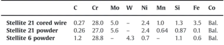
Table 1
Nominal chemical composition (wt%) of Stellite 21 cored wire (data given by Soudokay supplier) for MIG deposited hardfacings and of Stellite 21 and Stellite 6 powders (data given by Höganäs supplier) for LASER deposited hardfacings.
C Cr Mo W Ni Mn Si Fe Co Stellite 21 cored wire 0.27 28.0 5.0 – 2.4 1.0 1.3 3.5 Bal. Stellite 21 powder 0.26 27.0 5.6 – 2.4 0.64 0.87 0.1 Bal. Stellite 6 powder 1.2 28.8 – 4.3 0.7 – 1.1 0.6 Bal.
Table 2
Chemical composition (wt%) of the two substrates used for the elaboration of the tribological samples.
C Cr Mo Ni Nb Ti Al Fe
40NiCrMo18 0.40 1.50 0.50 4.50 – – – Bal. Inconel 718 0.04 18.00 3.00 Bal. 5.20 0.90 0.50 18.50
Fig. 1. Scheme of the high load Ring on Disc tribometer.
Table 3
Tribological test parameters of the reference test.
Initial contact temperature (1C) Room temperature (RT)
Normal load (N) 5000
Hertz contact pressure (MPa) 472
Sliding velocity 60 rpm (rotate) or 0.08 m/s (linear) Sliding distance (m) 144
Table 4
Tribological test parameters of the long duration test. Initial contact temperature (1C) Room temperature (RT)
Normal load (N) 5000 (for 120 min) then 3000 (for 360 min) Hertz contact pressure (MPa) 472 then 365
Sliding velocity 50 rpm (rotate) or 0.07 m/s (linear) Sliding distance (m) 480 then 1440
defined in the same conditions, for hemispherical contact surface of the rings before friction tests. In the case of the flat specimen, the reference surface is defined as the best-fit plane to all points outside of the wear scar. The wear volume of the flat surface (disc surface) is determined from the total area below the reference line (Fig. 2) integrated on the whole wear track (to calculate a volume) and the wear volume of the hemispherical contact surface of the rings is defined as the difference area between the worn profile and unworn profile (Figs. 3 and 4) integrated also on the whole wear track. 2.5. Crystallographic structure evaluation
The crystallographic structures have been investigated by X-ray diffraction (XRD) on the top surface of the hardfaced rings. Classical
θ
–2θ
scans, grazing incidence diffraction measurements at a low incident angle of 51 in order to restrict the X-ray radiation to a low penetration depth into the sliding surface of the rings and pole figure measurements have been performed. The estimated analysed depth is about 20 mm with classical scans and pole figure measurements while it is about 2 mm with grazing incidence diffraction at 51. 3. Results and discussion3.1. Characterisation of the as-deposited hardfacings
The main differences between the studied hardfacings are in nominal composition of the Stellites and in the deposit process.
Table 5compares the as-deposited chemical compositions measured by EDS with the nominal compositions given by the suppliers.
An important dilution phenomenon is observed in the case of the MIG processed material and the chemical composition is highly modified with an increase of the iron content coming from the tool steel substrate. In contrary, the LASER processed materials are not affected by the dilution phenomenon. If the LASER hard-facings present several layers, only one layer is deposited and observed on the ST21-MIG hardfacing.
The three Stellite hardfacing microstructures consist in cobalt rich dendrites and interdendritic regions containing primary carbides. Depending on alloying element content the primary carbides are Chromium, Tungsten or Molybdenum rich carbides.
Dendrite solidification is oriented perpendicularly to the substrate-hardfacing interface, according to the thermal gradient. Even it was not yet measured, because of the high level of carbon content, the volumetric fraction of interdendritic primary carbides of the ST6-LASER hardfacing is higher (Fig. 5). Moreover, the microstructure of the LASER hardfacings is finer than the MIG one. The hardness of the studied hardfacings, in the upper layer (the sliding layer) is reported inFig. 6. The hardness of Stellite materials is essentially due to the carbide precipitates and to a lesser extent to alloying element contents in the solid solutions. For Stellite hardfacings, the hardness depends on the deposit process, the number of deposited layers and the alloying element content plus the carbon content to form carbides. The highest hardness (508 HV0.3) is observed for the ST6-LASER hardfacing. The low
hardness of ST21-MIG (362 HV0.3) is induced by the iron dilution
in the first layer; however for multi-layers the hardness of the
Fig. 2. Procedure of calculation of the wear volume from scans of the flat contact surface of the disc.
upper layer can reach 400 HV0.3[8]. The ST21-LASER develops an
intermediary hardness of 426 HV0.3.
After machining and before friction test, the diffraction patterns of the hardfaced rings, exhibit various peaks mainly corresponding to the face-centered cubic (FCC) phase of cobalt (Fig. 7). A modification of the peak intensities in comparison with the JCPDS patterns shows that the surface seems to be textured with FCC-(200) planes preferentially oriented parallel to the sliding surface. The pole figure measurements realized on the two most intense peaks of the FCC structure, for example ST21-MIG ones are presented inFigs. 8 and 9, confirm this initial texture.
For the MIG processed hardfacing the initial crystallographic structure is entirely FCC. However, for the LASER processed hard-facings, a mixture of two allotropic FCC and hexagonal close-packed (HCP) phases with a greater amount of FCC phase is observed. The LASER deposition process seems to promote the HCP structure by the deposition process itself (deposition para-meters, cooling rate) as well as by a greater sensitivity to the strain-induced transformation of the LASER processed hardfacings that could be generated during the ring machining.
3.2. Tribological results 3.2.1. Friction coefficient values
The mean values of the friction coefficients are presented in
Table 6. The friction coefficient of the ST21-MIG process is stable with
an average value of 0.3370.04. In contrast, the mean friction coefficient values of LASER hardfacings are less. These results can be correlated to the XRD analyses (Section 3.2.5.) that have shown different plastic strain mechanisms between the MIG and the LASER processed hardfacings: under tribological stresses, the strain-induced FCC to HCP phase transformation is observed only for the LASER hardfacings. As reported by Persson[16], under high normal load and several strokes, the HCP planes are tilted and aligned parallel to the
Fig. 4. Procedure of calculation of the wear volume from scans of the hemispherical contact surface of the ring. Table 5
Chemical composition (wt%) of the studied materials: before (data given by Höganäs and Soudokay suppliers) and after the welding deposition process (data measured by EDS).
ST21-MIG ST21-LASER ST6-LASER Cored wire Deposited Powder Deposited Powder Deposited C 0.27 (a) 0.26 (a) 1.2 (a) Cr 28.0 20.26 27.0 26.75 28.8 28.11 Mo 5.0 3.24 5.6 4.65 – 0.62 W – – – – 4.3 3.00 Ni 2.4 2.80 2.4 2.30 0.7 1.10 Mn 1.0 1.16 0.64 0.78 – 0.44 Si 1.3 1.00 0.87 0.91 1.1 0.81 Fe 3.5 30.73 0.1 0.60 0.6 0.79
Co Bal. Bal. Bal. Bal. Bal. Bal.
sliding surface (on few nanometres thick) and are responsible of the lowest friction factor of LASER hardfacings.
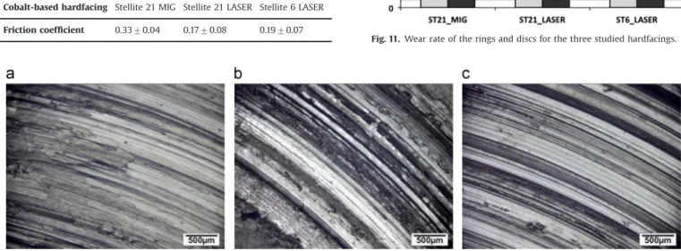
3.2.2. Worn surface observations
Optical observations of the wear track of the ring rubbing surfaces highlight concentric scratches that are characteristic of ploughing wear (Fig. 10). The wear volumes calculated from surface topographic measurements of the rings and of the discs after tribological tests (Fig. 11) show that the volume loss is more important for the MIG processed Stellite than for LASER processed Stellites. For LASER processed Stellites, the ring volume loss is higher for Stellite 6 than for Stellite 21. In these two last cases, the
disc volume loss is in the same magnitude. The hardness can be correlated to the abrasive wear resistance and it is in good accordance with the MIG deposited Stellite behaviour versus
Fig. 5. Initial microstructure of the three studied hardfacings: (a) ST21-MIG, (b) ST21-LASER, and (c) ST6-LASER.
Fig. 6. Initial hardness of the last deposited layer, corresponding to the sliding surface of the three studied hardfacings.
Fig. 7. Conventional θ–2θ scans performed on the surface of the machined rings.
Fig. 8. FCC-(111) planes pole figure before friction test: no preferred orientation is observed (example performed on ST21-MIG).
Fig. 9. FCC-(200) planes pole figure before friction test: preferred orientation parallel to the sliding surface (example performed on ST21-MIG).
LASER deposited Stellites. The beneficial contribution of hardness is balanced by the microstructure (volumetric fraction of carbides) contribution because in regards with the two LASER processed samples, the highest hardness is not correlated to the highest wear resistance. This result could be attributed to the contribution of the hard carbides that are worn out and that circulate into the contact and become very abrasive.
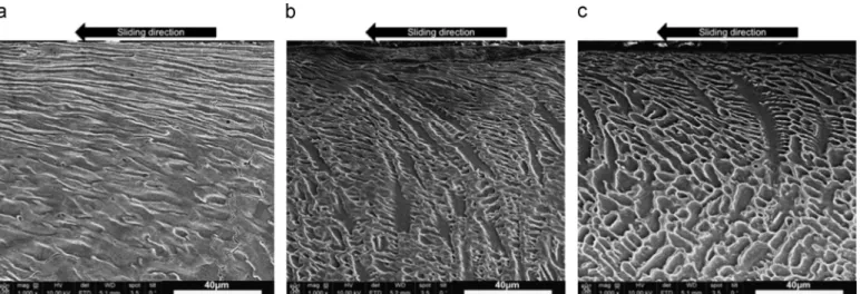
3.2.3. Cross-section observations
Post-mortem SEM observations have been carried out on cross-sections of the rings, in parallel to the sliding surface. The observed samples have been polished until 1 mm and electrolytically etched using a EtOH-50 vol%/HCl-50 vol% solution.
The plastic strain of the Stellite is well demonstrated, with a grain reorientation according to the sliding direction (Fig. 12). Whatever the hardfacing, in the upper surface, the dendrites are plastically sheared and crushed with a large plastic flow.
Dendrite shearing seems to be more important for ST21-MIG, due to a lower contribution of the interdendritic carbides content which could induce less mechanical shear resistance.
At higher magnification, no cracks are clearly noticeable in the carbides (Fig. 13). The interdendritic carbides are more or less embedded in the interdendritic plastic flow and reveal the shear-ing deformation. It can be concluded that the main velocity accommodation mechanism in the contact is the shearing of dendrites and interdendritic spaces.
3.2.4. Work-hardening
To identify the level of work-hardening, post-mortem Vickers micro-hardness measurements at 300 g of the plastically sheared area of the upper surface of the deposits have been carried out on cross-sections of the ring samples after specular polishing (Fig. 14). The evolution of the hardness measurements verifies that, what-ever the deposit process, the Stellite grades are work-hardened after friction tests. A gradient of hardness is observed on the first millimetre of the sliding surfaces and the total plastically deformed thickness is about 700 mm for the LASER hardfacings and about 500 mm (Fig. 14) for the MIG deposit. In the upper part of the plastically deformed area, the hardness reaches to a maximal value of around 700 HV0.3measured at 30 mm from the
sliding surface because the size of the Vickers indents (Fig. 14). So, the high levels of hardness, measured after friction tests, are in the same range whatever the Stellite composition or the deposit
processes and point out that work-hardening is preferentially induced by the plastic deformation of dendrites and interdentritic spaces, more than by the carbide contents.
Moreover, if the value of 700 HV0.3seems to correspond to the
ultimate hardness for these hardfacings before the emission of wear particles into the contact, the work-hardening rate decreases with a lower iron dilution: ST21-MIG (88%)-ST21-LASER (64%)-ST6-LASER (41%) (Fig. 15). This result is different from the results of Fouilland et al. [8]that have observed an increase of the work-hardening rate with a decrease of iron dilution for a Stellite 21 deposited by the MIG process. In Fouilland et al.[8]study, only the MIG process is investigated as well as no phase transformation analyses have been performed. This behaviour difference could so be correlated with the FCC to HCP phase transformation observed in the LASER processed hardfacings (Section 3.2.5). The activation of the phase transformation mechanism could explain this less important work-hardening rate as discussed in Section 3.2.5.
A relationship between the plastic strain and the micro-hardness has been established (Figs. 16 and 17) through micro-hardness meas-urements (100 g) performed along plastic-strained dendrites of ST21-MIG after a long-test duration (Table 4). The Dautzenberg calculation method[17]operated to determine the plastic strain rate has been applied through the interdendritic carbides revealed by a Murakami chemical etching that highlights the dendrite plastic strain (Fig. 16). It is observed that beyond a plastic strain threshold of around 600%, the hardness achieves an asymptotic level (660 HV0.1) and does not
change with more straining. So, considering these first observations, before this specific threshold (600%), the plastic straining mechanisms induce work-hardening mechanism and beyond this level, another plastic straining mechanism could be activated, allowing very high levels of deformation (up to 1000%) without additional work-hardening. This assessment has to be confirmed with nano-hardness measurements in the upper parts of the friction zones (a few
Table 6
Mean values of friction coefficient during unlubricated_RT_5000 N_60 rpm_144 m tests. Cobalt-based hardfacing Stellite 21 MIG Stellite 21 LASER Stellite 6 LASER Friction coefficient 0.3370.04 0.1770.08 0.1970.07
Fig. 10. Optical observation of ring surfaces after tribological test (a) ST21-MIG, (b) ST21-LASER and (c) ST6-LASER.
micrometres) coupled with Electron Beam Scattered Diffraction (EBSD) characterisations.
3.2.5. Crystallographic structure evolution
Classical
θ
–2θ
scans (analysed depth around 20 mm) of the worn surfaces show that only FCC cobalt phase is present for the ST21-MIG whereas both FCC and HCP phases can be detected inthe case of ST21-LASER and ST6-LASER (Fig. 18). The grazing incidence diffraction (analysed depth around 2 mm) confirms these results and highlights that the crystallographic structure evolu-tions are mainly observed in the first micrometres of the sliding surfaces (Fig. 19).
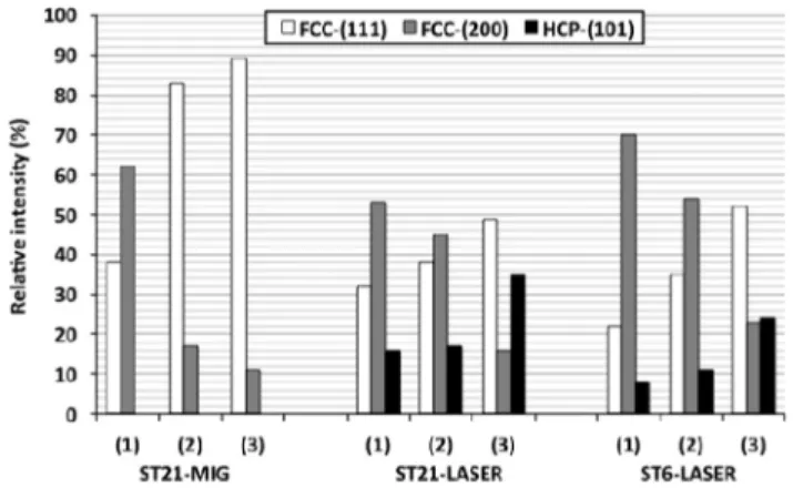
The crystallographic structure evolution is discussed by com-paring the relative intensities of the three main peaks of the cobalt structures (Fig. 20) and by pole figure measurements (Fig. 21). For each studied hardfacing, the plastic strain induces a grain
Fig. 12. SEM observations of the sliding surfaces in cross-sections: (a) ST21-MIG, (b) ST21-LASER and (c) ST6-LASER.
Fig. 13. SEM observations of the sliding surfaces in cross-sections: (a) ST21-MIG, (b) ST21-LASER and (c) ST6-LASER.
Fig. 14. Gradient of hardness on cross-sections of the three studied hardfacings and determination of the work-hardened layer thickness by comparison with the initial micro-hardenesses.
Fig. 15. Work-hardening of the three studied hardfacings, comparison of the initial hardnesses and the hardnesses obtained after friction test (measurements have been performed on cross-sections, at 30 mm from the sliding surface).
reorientation (Fig. 20) that may be due to classical plasticity mechanisms such as dislocations slip.
For ST21-MIG, due to friction test, the FCC-(111) plane relative intensities increase while the FCC-(200) plane relative intensities decrease. This observation is especially verified with the grazing incidence results where the amount of FCC-(111) planes parallel to the surface is higher in the first 2 mm than in the first 20 mm and in return, the amount of FCC-(200) planes is lower in the first analysed 2 mm than in the first 20 mm (Fig. 20). This phenomenon highlights a grain reorientation induced by plastic strain under tribological stresses with a gradient below the sliding surface. Moreover, the pole figure measurements (20 mm analysed depth) confirm that grain reorientation because the FCC-(111) planes are preferentially oriented parallel to the sliding surface (Fig. 21a) and
the FCC-(200) planes are tilted by around 451 toward the sliding direction (Fig. 21b).
As foreword, for the LASER hardfacings, the peak with a 2
θ
angular position between 511 and 521 could be attributed to FCC-(111) or HCP-(002) planes but it is impossible to dissociate them from XRD scans (Figs. 18 and 19). Looking at the pole figures, the planes corresponding to a 2θ
angular position between 511 and 521 (Fig. 21c and f) are similarly oriented to HCP-(101) planes (Fig. 21e and h). So, it is impossible to attribute them to HCP-(002) planes and the peak with a 2θ
angular position between 511 and 521 has to be attributed to FCC-(111).For the LASER hardfacings, due to friction test, the FCC-(111) and HCP-(101) plane relative intensities increase while the FCC-(200) plane relative intensities decrease (Figs. 19 and 20). The grazing measurements in the first micrometres (2 mm) of the plastic deformation area show a grain reorientation analogous with ST21-MIG (Fig. 19) because in the upper friction surface, the FCC-(111) planes are preferentially oriented parallel to the sliding surface. In Fig. 20, the variation of the peak relative intensities between the conventional configuration and the grazing incidence configuration, after friction test, reveals a gradient in grain reorientation and shows that the grain reorientation is not as pronounced as for ST21-MIG. Moreover, for LASER hardfacings, the level of plastic strain has been high enough to induce the allotropic transformation from FCC to HCP phase of the cobalt and a gradient of strain-induced transformation is observed below the sliding surfaces (Fig. 20). The pole figure measurements, within the 20 mm analysed depth, show that the FCC-(200) planes are still mainly oriented parallel to the sliding surface (Fig. 21d
Fig. 16. Microscopic observation of the plastic strain and Vickers micro-hardness indents realized on ST21-MIG.
Fig. 17. Relationship between plastic strain rate and hardness on a ST21-MIG hardfacing.
Fig. 18. Conventional θ–2θ scans performed on the sliding surfaces after tribolo-gical test (analysed depth about 20 mm).
Fig. 19. Grazing incidence scans performed on the sliding surfaces after tribological test (analysed depth about 2 mm).
Fig. 20. Peak relative intensities of the three studied hardfacings calculated from XRD measurements performed on the ring surfaces: (1) conventional configuration before tribological test, (2) conventional configuration after tribological test, and (3) Grazing incidence configuration after tribological test.
and g) and FCC-(111) planes are preferentially oriented at 451 toward the sliding direction (Fig. 21c and f). Pole figure measure-ments performed on HCP-(101) planes are similarly oriented as FCC-(111) planes (Fig. 21c, e, f and h). So, the strain-induced transformation from FCC to HCP phase seems to occur in FCC-(111) planes as observed by Farooq et al.[13]in the case of tensile tests. Atamert and Bhadeshia[12] have shown that the stacking faults are always contained on FCC-(111) planes.
Consequently, two mechanisms of plastic strain are observed: grain reorientation supposed by dislocations slip and phase
transformation due to intrinsic faults on every second plane. In the case of ST21-MIG, the plastic strain induces a grain reorientation of the ST21-MIG with a strong texture of FCC-(111) parallel to the sliding surface and no strain-induced transformation. However, for LASER processed Stellites (ST21-LASER and ST6-LASER), the plastic straining induces both a phase transformation from FCC to HCP structure and a grain reorientation less important than for the ST21-MIG. It can be noticed that the combination of these two mechan-isms of plastic strain is responsible of less grain reorientation and so probably of less dislocations slip explaining the lower
Fig. 21. Pole figure measurements of FCC-(111), FCC-(200) and HCP-(101) planes on worn surfaces of ST21-MIG, ST21-LASER and ST6-LASER hardfacings (the analysed depth is about 20 mm). (a): ST21-MIG_FCC-(111), (b): ST21-MIG_FCC-(200), (c): ST21-LASER_FCC-(111), (d): ST21-LASER_FCC-(200), (e): ST21-LASER_HCP-(101), (f): ST6-LASER_FCC-(111), (g): ST6-LASER_FCC-(200) and (h): ST6-LASER_HCP-(101).
work-hardening observed in LASER processed Stellites, as presented inSection 3.2.4.
4. Conclusion
This study deals with wear mechanisms of three Stellite hard-facings, in the context of wear improvement of hardfaced forging tools. This study has been performed on Stellite 21 deposited by the MIG process, the commonly used hardacing to protect and repair aeronautic forging dies and on Stellite 6 and Stellite 21 deposited by the LASER process in order to examine the influence of the chemical composition and of the deposition process on the plastic straining of cobalt-based hardfacings under friction loadings.
The tribological behaviour has been performed on a high load Ring on Disc tribometer. The main results, focused on plastic shearing deformation under friction loadings, assess that: " The as-deposited hardness of cobalt-based hardfacings can be
increased by a higher carbon content and by reducing the iron dilution during the deposition process.
" The wear resistance of Stellites not only depends on their initial hardness, but is also influenced by the microstructure and the carbide content.
" Stellites are able to very high levels of plastic strain (up to 1000%) under tribological stresses.
" The Stellite hardness increases under friction loadings with an ultimate value of about 700 HV0.3 (30 mm depth from the
surface) that seems to be independent of the hardfacing chemical composition and deposition process.
" A relationship between the plastic strain level and the micro-hardness has been established. A work-hardening threshold is observed and seems to correspond to the activation of a different deformation mechanism promoting more strain with-out any increase of the micro-hardness.
" The plastic straining of Stellites has been highlighted by XRD analyses and seems to occur by two different mechanisms depending on the iron dilution: for high (MIG) or low (LASER) iron dilution levels, the plastic strain causes respectively a reorientation of grains or a combination of grains reorientation with a FCC to HCP phase transformation; the latter being associated with a lower friction coefficient.
The results show that the material/process couple is important in order to adjust the carbon content directly influencing the hardness by carbide precipitation and in order to limit the dilution level promoting FCC to HCP strain-induced phase transformation that induces a decrease of the friction coefficient. The results on the LASER process hardfacings are therefore significant for forging tool applications because in function of the hardfacing process, the
shear stress at the tool surface will be lower and their wear resistance will be improved.
Acknowledgements
This work is part of ROOF2 project. It is a FUI12 project labialized by the competitiveness clusters ViaMeca, Aerospace Valley and the European center of ceramics. The ROOF2 project is funded by the Auvergne FEDER, the Auvergne Region, the Allier General Council, the FUI, the Saint-Etienne Metropolis, the Indre General Council, the Limousin Region and the Limousin FEDER. References
[1]M. Farhani, A. Amadeh, H. Kashani, A. Saeed-Akbari, The study of wear resistance of a hot forging die, hardfaced by a cobalt-base superalloy, Mater. Forum 30 (2006) 212–218.
[2]Q.Y. Hou, J.S. Gao, F. Zhou, Microstructure and wear characteristics of cobalt-based alloys deposited by plasma transferred arc welding surfacing, Surf. Coat. Technol. 194 (2005) 238–243.
[3]I. Radu, D.Y. Li, R. Llewellyn, Tribological behavior of Stellite 21 modified with yttrium, Wear 257 (2004) 1154–1166.
[4]J.C. Shin, J.M. Doh, J.K. Yoon, D.Y. Lee, J.S. Kim, Effect of molybdenum on the microstructure and wear resistance of cobalt-base Stellite hardfacing alloys, Surf. Coat. Technol. 166 (2003) 117–126.
[5]A.S. D’Oliveira, P.S. Da Silva, R. Vilar, Microstructural features of consecutive layers of Stellite 6 deposited by laser cladding, Surf. Coat. Technol. 153 (2002) 203–209.
[6]J.L. De Mol, Van Otterloo, J.TH.M. De Hosson, Microstructural features and mechanical properties of a cobalt-based laser coating, Acta Mater. 45 (1997) 1225–1236.
[7]T.C. Sims, N.S. Stoloff, W.C. Hagel, Superalloys II, Wiley, New-York, 1987. [8]L. Fouilland, M. El Mansori, A. Massaq, Friction-induced work hardening of
cobalt-base hardfacing deposits for hot forging tools, J. Mater. Process. Technol. 209 (2009) 3366–3373.
[9]L. Fouilland, M. El Mansori, M. Gerland, Role of welding process energy on the microstructural variations in a cobalt base superalloy hardfacing, Surf. Coat. Technol. 201 (2007) 6445–6451.
[10]H. Kashani, M. Sadeghi Laridjani, A. Amadeh, M. Khodagholi, S. Ahmadzadeh, The influence of volumetric dilution on the strain inducedγ-ε martensitic transformation in GTAW processed Co–Cr–Mo alloy, Mater. Sci. Eng. A 478 (2008) 38–42.
[11]H. Kashani, A. Amadeh, H.M. Ghasemi, Room and high temperature wear behaviors of nickel and cobalt base weld overlay coatings on hot forging dies, Wear 262 (2007) 800–806.
[12]S. Atamert, H.K.D.H. Bhadeshia, Comparison of the microstructures and abrasive wear properties of stellite hardfacing alloys deposited by arc welding and laser cladding, Metall. Trans. A 20 (1989) 1037–1054.
[13]M.U. Farooq, U. Klement, G. Nolze, The role ofα- toε-Co phase transformation on strain hardening of a Co-Cr-Mo laser clad, Mater. Sci. Eng. A 445–446 (2007) 40–47.
[14]D.H.E. Persson, S. Jacobson, S. Hogmark, Antigalling and low friction properties of a laser processed co-based material, J. Laser Appl. 15 (2003) 115–119. [15]E. Cabrol, C. Boher, V. Vidal, F. RezaÏ-Aria, F. Touratier, A wear damage
assessment of high temperature forging tool, Adv. Mater. Res. 966-967 (2014) 103–110.
[16]D.H.E. Persson, On the Mechanisms behind the Tribological Performance of Stellites, Digit. Compr. Summ. Upps. Diss. Fac. Sci. Technol. 129 (2005). [17] J.H. Dautzenberg, Quantitative determination of deformation by sliding wear,