ISMRE2018/XXXX-2018 ALGERIA
Method to extract the model parameters of solar
cells using the I-V characteristics
Khaled MAHI1,2 and Hocine AÏT-KACI1
1Physics of Plasmas and Conductors Materials and their Applications Laboratory (P.P.C.M.A.L)
Department of Physics, B.P.1505 El M’Naouar, Oran, Algeria
2Department of Physics, Faculty of Sciences of the Matter, Ibn Khaldoun University of Tiaret,
BP P 78, Zaaroura, Tiaret, Algeria
mahikhalidou@yahoo.fr
Abstract– With the increase in the capacity of photovoltaic
generation systems, studies are being actively conducted to improve system efficiency. To develop precise solar cell simulators or design a high-performance photovoltaic generation system, it is important to accurately understand the physical properties of solar cells. However, solar cell models have a non-linear form with numerous parameters. To obtain accurate parameter values, assumptions that differ from real operating conditions must be made to avoid computational complexity. In this work, we proposed a new method to analyze the experimental current-voltage of the solar cell models, and to the numerically extraction of the intrinsic solar cells parameters (i.e., the ideality factor and the series resistance). The method suggested in the present paper is based on the use of an external variable resistor put in series with the solar cell studied. The validity of these methods is confirmed by its application to current–voltage theoretical and experimental characteristics.
Keywords–Solar cell model; Parameter extraction; series resistanc; Ideality factor; I–V characteristics
I. INTRODUCTION
An accurate knowledge of solar cell model parameters from measured current–voltage (I–V) characteristics is of vital importance for the quality control and evaluation of the performance of the solar cells.
Several methods have been suggested for extracting the series resistance of a solar cell [1–5]. Some of the suggested methods involve both illuminated and dark I–V characteristics [1,2], while others use dynamic measurements [3] or integration procedures [5] based on computation of the area under the current–voltage curves. However, the other parameters have not received the same amount of attention, and few methods of extracting the five parameters have been proposed [6,10–12].
Recent methods [6–9] have been successfully applied to different solar cells. Ortiz-Conde et al. [6] have proposed an elegant method to extract the five parameters based on the calculation of the co-content function (CC) from the exact explicit analytical solution of the illuminated current–voltage characteristics, but this method has only been tested on a plastic solar cell. An accurate method using the Lambert W-function has been presented by Jain and Kapoor [7] to study different parameters of solar cells, but it has been validated only on simulated I–V characteristics. A combination of lateral and vertical optimization was used [8] to extract the parameters of an illuminated solar cell.
The parameter extraction method proposed in this paper uses characteristics of the diode I–V curve to extract the series resistance and the ideality factor from the measured I–V curve of the solar cell. Our method consists in the imposing an external variable resistor put in series with the solar cell studied.
II. THEORY AND APPLICATION
The current–voltage relation for a solar cell under illumination is given by [13] p d ph
I
I
I
I
)
(
1
)
(
exp
V
R
I
G
V
R
I
n
I
I
I
ph S S
sh
S
(1)Iph, Is, n, Rs and Gsh being the photocurrent, the diode saturation current, the diode quality factor, the series resistance
ISMRE2018/XXXX-2018 ALGERIA
and the shunt conductance, respectively. q /kTis the usual inverse thermal voltage.
For large negative bias voltages –qV«kT with shunt
resistance Rsh = (1/Gsh)>Rs, which is usually true, the shunt conductance Gsh is evaluated from the reverse bias characteristics by a simple linear fit [11]. The calculated value of Gsh gives the shunt current Ip = GshV which can be subtracted in turn from the measured current to yield the current across the solar cell.
Under forward bias for V+RsI
»
kT The current across the diode is given by
exp
(
V
R
I
)
n
I
I
I
ph S
S (2)As mentioned bellow, our proposed technique, for the determination of the series resistance and the ideality factor is to impose a variable resistance in series with the sample studied according to the following equation:
exp
(
V
(
R
R
)
I
)
n
I
I
I
ph S S is
(3) OrI
R
R
I
q
nkT
I
I
q
nkT
V
ln(
ph
)
ln(
S)
(
S
i)
(4)In our suggested method we need only two values of the externals resistances R1 and R2, but for more confirmation of the value of the series resistance Rs obtained one can take several values of Ri, the equation (4) given by:
i S S i ph i
I
R
R
I
q
nkT
I
I
q
nkT
V
ln(
1)
ln(
)
(
1)
1 (5) i S S i ph iI
R
R
I
q
nkT
I
I
q
nkT
V
ln(
2)
ln(
)
(
2)
2 (6)By addition Eq. (5) and Eq. (6), we obtain
i i i i S S i ph i ph iI
R
I
R
I
I
R
I
q
nkT
I
I
I
I
q
nkT
V
2 2 1 1 2 1 2 1)
(
)
ln(
2
)
)(
(
ln
2
(7)For another value of Vj, we obtain
j j j j S S j ph j ph jI
R
I
R
I
I
R
I
q
nkT
I
I
I
I
q
nkT
V
2 2 1 1 2 1 2 1)
(
)
ln(
2
)
)(
(
ln
2
(8)By subtracting Eq. (7) from Eq. (8), we obtain
)
(
)
)(
(
)
)(
(
ln
)
(
)
(
)
(
2
2 1 2 1 2 1 2 1 2 2 2 1 1 1 i i j j S j ph j ph i ph i ph j i j i j iI
I
I
I
R
I
I
I
I
I
I
I
I
q
nkT
I
I
R
I
I
R
V
V
(9)Eq. (9) can be written in a simpler form:
Z
R
Y
q
nkT
X
S (10) Where)
(
)
(
)
(
2
V
iV
jR
1I
1iI
1jR
2I
2iI
2jX
)
)(
(
)
)(
(
ln
2 1 2 1 j ph j ph i ph i phI
I
I
I
I
I
I
I
Y
i i j jI
I
I
I
Z
1
2
1
2Firstly we divided the Eq. (10) by Y and secondly by Z, we defined two new quantities X/Y and X/Z as follow:
Y
Z
R
q
nkT
Y
X
S
(11) and SR
Z
Y
q
nkT
Z
X
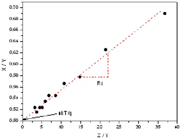
(12)According to Eq. (11) a plot of X/Y as a function of Z/Y should produce a straight line with slope RS and ordinates axis intercept of nkT/q. Similarly, according to Eq. (12) a plot of X/Z as a function of Y/Z should produce a straight line with slope nkT/q and ordinates axis intercept RS. The use of either one of these equations represents the basis of the proposed technique.
ISMRE2018/XXXX-2018 ALGERIA
For most practical illuminated solar cells, we usually consider that Is
«
Iph, the photocurrent can be given by the approximationIsc ≈ Iph, where Isc is the short circuit current. This approximation is highly acceptable, and it introduces no significant errors in subsequent calculations [12].
The saturation current Is was evaluated using a standard method based on the I–V data by plotting ln(Iph-I) versus V. where the I–V data were corrected taking into account the effect of the series resistance.
III. DISCUSSION
In order to test the effectiveness of the method, it is applied to the synthetic I-V characteristics of figure 2, corresponding to a single exponential expression, of the type of equation (3), with Is = 13.6 10-9A, n = 2.32, Rs = 8.59 Ω, Iph =7.94 10-3A and three different values of series external resistances Ri =
8.79 , 8.99 and 9.19 Ω. These parameters were chosen by
Ortiz-Conde et al. [6], so as to produce results comparable to the experimental data. Then we extract the different parameters, considering the synthetic I–V characteristics and using our method.
In our suggested method we need only two values of the externals resistances, but for more confirmation of the value of the series resistance Rs obtained one can take several values of
Ri, as an example let us take two following resistances: R1=8.79 Ω and R2=8.99 Ω. 0.0 0.2 0.4 0.6 0.8 1.0 1.2 0.0 0.2 0.4 0.6 0.8 1.0 Rs = 8.59 Rs = 8.79 Rs = 8.99 Rs = 9.19 Cu rr e n t ( A) Voltage (Volts)
Fig. 1. Current-voltage characteristics of a solar cell simulated by (3) with Is = 13.6 10-9A, n =2.32, Rs = 8.59. and three different values of series
external resistances Ri = 8.79 , 8.99 and 9.19 Ω
The corresponding plot of auxiliary function X/Y as calculated by Eq. (11) is presented in figure 3. A value of Rs =
8.60 Ω can be extracted from its slope, and the ordinates axis
intercept gives an extracted value of n=2.31. Alternatively, a plot of auxiliary function X/Z as calculated by Eq. (12) is shown in figure 4. It has a slope that corresponds to a value of
n=2.32, and an ordinates axis intercept corresponding to an
extracted value of Rs =8.58 Ω. It is clear that all the parameters extracted with the proposed method are in excellent agreement with their theoretical values.
Fig. 2. Plot of (11) using simulated data of Fig. 1. the slope gives an extracted value of Rs = 8.60 Ω, and the ordinates axis intercept gives an extracted value of n=2.31.
Fig. 3. Plot of (12) using simulated data of Fig. 1. The slope gives an extracted value of n=2.32, and the ordinates axis intercept gives an extracted value of Rs =8.58 Ω.
ISMRE2018/XXXX-2018 ALGERIA
In the last part of this paper we present a experimental comparison of our proposed methods with the set of other methods [6,14] for the purpose to make a comparison with our proposed methods. The obtained results are shown in Table 1. Good agreement is obtained between the parameters used in modelling and the extracted values.
TABLE 1 EXPERIMENTAL EXTRACTED PARAMETERS VALUES OF A COMMERCIAL SILICON SOLAR CELL USING
VARIOUS METHODS Solar cell Parameter Experimental Values Ortiz-Conde [6] Chegaar [14] In this wark Rs (Ω) 8.59 8.586 8.59 8.59 n 2.32 2.59 2.31 2.31 Is (A) 13.6 10-9 3.29 10-9 13.6 10-9 13.6 10-9 IV. CONCLUTION
In this paper, a simple and powerful method of extracting parameters of a solar cell model was proposed. The proposed method is useful for the accurate and easy extraction of solar cell parameters from the I–V curve provided by the manufacturer or a measured I–V curve.
The method has been on the successfully applied to commercial solar cells and the results obtained are in good agreement with those published previously. The method is very simple to use and presents the advantage of being independent of the voltage step. It allows real time characterisation of different types of solar cells and modules in indoor or outdoor conditions.
REFERENCES
[1] Wolf M, Rauschenbach H. Series resistance effects on solar cells measurements. Adv Energy Convers 1963;3:455–79. [2] Rajkanan K, Shewchun J. A better approach to the evaluation
of the series resistance of solar cells. Solid-State Electron 1979;22:193–7.
[3] Boucher J, Lescure M, Vialas J, Determination of series resistance of a solar cell by dynamic methods. In: Proc. 1st European community photovoltaic solar energy conference. 1978. p. 1044.
[4] Radziemska E. Dark I–U–T measurements of single crystalline silicon solar cells. Energy Convers Manage 2005;46:1485–94.
[5] Araujo GL, Sanchez E. A new method for experimental determination of the series resistance of a solar cell. IEEE Trans Electron Dev 1982;29:1511–3.
[6] Ortiz-Conde A, Garcia Sanchez FJ, Muci J. New method to extract the model parameters of solar cells from the explicit analytic solutions of their illuminated I–V characteristics. Solar Energy Mater Solar Cells 2006;90:352–61.
[7] Jain A, Kapoor A. A new approach to study organic solar cell using Lambert W-function. Solar Energy Mater Solar Cells 2005;86: 197–20
[8] Haouari-Merbah M, Belhamel M, Tobias I, Ruiz JM. Extraction and analysis of solar cell parameters from the illuminated current voltage curve. Solar Energy Mater Solar Cells 2005;87:225–33.
[9] Kaminski A, Marchand J J, Laugier A. Non ideal dark I–V curves behaviour of silicon solar cells. Solar Energy Mater Solar Cells 1998;51:221–31.
[10] Easwarakhanthan T, Bottin J, Bouhouch I, Boutrit C. Nonlinear minimization algorithm for determining the solar cell parameters with microcomputers. Int J Solar Energy 1986;4:1–12.
[11] Ouennoughi Z, Chegaar M. A simple method for extracting solar cell parameters using the conductance method. Solid-State Electron 1999;43:1985–8.
[12] Chegaar M, Ouennoughi Z, Guechi F. Extracting dc parameters of solar cells under illumination. Vacuum 2004;75:367–72.
[13] Engin Karatepe, Mutlu Boztepe, Metin Colak. Neural network based solar cell model. Energy Convers Manage 2006;47:1159–78.
[14] Chegaar. M , Azzouzi. G, Mialhe. P. Simple parameter extraction method for illuminated solar cells Solid-State E lectron 2006;50:1234–37.