HAL Id: hal-02900608
https://hal.archives-ouvertes.fr/hal-02900608
Submitted on 16 Jul 2020
HAL is a multi-disciplinary open access
archive for the deposit and dissemination of
sci-entific research documents, whether they are
pub-lished or not. The documents may come from
teaching and research institutions in France or
abroad, or from public or private research centers.
L’archive ouverte pluridisciplinaire HAL, est
destinée au dépôt et à la diffusion de documents
scientifiques de niveau recherche, publiés ou non,
émanant des établissements d’enseignement et de
recherche français ou étrangers, des laboratoires
publics ou privés.
An application of the context transfer protocol : IPsec in
a IPv6 mobility environment
Jean-Marie Bonnin
To cite this version:
Jean-Marie Bonnin. An application of the context transfer protocol : IPsec in a IPv6 mobility
environ-ment. BWIA’07 : International workshop on Broadband wireless Internet access, Aug 2007, Ontario,
Canada. �hal-02900608�
An application of the Context Transfer Protocol:
IPsec in a IPv6 mobility environment
Fabien ALLARD
France T´el´ecom R&D 38-40 rue du G´en´eral Leclerc F-92794 Issy-Les-Moulineaux Email: [email protected]
Jean-Marie BONNIN
GET/ENST Bretagne CS17607 F-35576 Cesson S´evign´e Email: [email protected]Abstract—The use of the Internet must be able to be in confidence for users but security provisioning has a cost for ISPs1. In a mobility context this security must be set up from scratch after each handover and for each customer. Therefore, a mechanism has been designed in the standardization bodies: the Context Transfer. This mechanism aims to transfer suitable information between equipments in order to reduce handover time. The benefit for an operator would then be a same security level during and after handover in mobile networks but with a cost as lower as possible. The purpose of this paper is to set out an application of the Context Transfer Protocol to IPsec2 in
a IPv6 mobile environment. After a state of the art of context transfer for security, the paper quickly presents CXTP3 defined
at the IETF4. Then, it defines the IPsec context and finally, it describes a CXTP based solution to transfer this context between two access routers in a IPv6 mobility environment.
Index Terms—Context transfer, CXTP, network security, IPsec, network mobility.
I. INTRODUCTION
Security provisioning is a major requirement in an all-IP-based network architecture providing multimedia services specially for mobile users. Indeed, IP communications are more vulnerable to attacks when mobile nodes use wireless links. To set up security, messages are exchanged during the network access phase between mobile nodes and network equipements - working as network access controllers - such as access points (e.g. [1]), access routers (e.g. [2]) or AAA5
servers (e.g. [3] or [4]). However, this signalisation can be important and can take a significant amount of time, cru-cially affecting the handoff performance. Furthermore, in a near future the majority of terminals will be mobile. Hence, growth of the number of mobile nodes will increase number of protocol messages exchanged between mobile nodes and other involved entities e.g. access routers, AAA servers, etc. Thus, data processing charge in network equipements (e.g. for cryptographic material generation) will be more and more important.
In this paper, a context transfer solution is proposed in order to support seamless handovers and to decrease data
1Internet Service Providers
2Security Architecture for the Internet Protocol 3Context Transfer Protocol
4Internet Engineering Task Force
5Authentication, Authorization, Accounting
processing charge in equipements. The aim of this mechanism is to transfer the network states informations relevant to a mobile node to follow it during its movements. Hence, as soon as the mobile node moves, the states must be restored in the new equipment. A network state, typically called a context, is a set of informations installed by services on network equipements in charge of controlling the access. Such services are known as context transfer candidate services and examples include IEEE 802.11i, IPsec and AAA protocols [5], QoS6
policy, header compression, etc. Therefore, a context transfer protocol can help in avoiding a complex and time consuming re-establishement of these services at the new location.
The context of our works is the following: a mobile node using Mobile IPv6 sets up a VPN7 i.e. typically an IPsec tunnel with an access router after a successfull authentication (e.g. using PANA8 [12]). After a complete authentication, the MN and the AR configure their IPsec databases (see section V) to protect the whole MN’s traffic. When a handover occurs, the MN should re-authenticated itself to regain access to the network since the new AR IPsec databases are not configured. Thus, the whole authentication processing has to be set up from the beginning to re-establish the IPsec tunnel. In most of authentication framework, this procedure takes a lot of time and can be very critical for real time services running on the MN. The purpose of this paper is to prove the viability of the context transfer mechanism for IPsec in a IPv6 mobility environment. Section 3 makes a state of the art of context transfer solutions for security protocols. Section 4 gives an overview of a context transfer protocol which has been specified at the IETF: CXTP. Section 5 explains how CXTPcan manage IPsec security associations and presents the IPsec context which is transferred. Finally, section 6 describes our local platform where suggested solutions are currently being implemented and shows in details the implementation of CXTP for IPsec.
II. GLOSSARY
• MN : Mobile Node.
• HA: Home Agent.
6Quality of Service 7Virtual Private Network
• AR : Access Router.
• pX : previous X.
• nX : new X.
• SA: Security Association.
• SP: Security Policy.
• SAD : Security Association Database.
• SPD : Security Policy Database.
• Co@ : Care-of Address.
III. CONTEXT TRANSFER TO OPTIMIZE SECURITY
Previous studies in the research community have already been done on the use of context transfer to optimize security re-establishment after a handover. Among those, authors of [6] gives a global view of this mechanism for security. They examine where context transfer can be applied in an ambient network, the security considerations, the transfer of security state information, security context transfer for session mobility and security issues of context transfer for both homogeneous and heterogeneous environments.
At link level, [7] propose a proactive key distribution method in order to reduce the authentication exchanges be-tween the station and the network to its minimum while guar-antying conformity with the IEEE 802.11i security proposal. One of the proposed methods uses IAPP9 which is a mecha-nism developed at IEEE. It allows to transfer context related to mobile station between 802.11 access points. The authors proves thanks to actual experimentation that re-authentication latency is reduced enough to allow real time applications to sustain fast secure handoffs.
At network level, some IETF drafts have been published on context transfer for IPsec: [8] describes issues that need to be considered for transferring IPsec related context between access routers. [9] and [10] detail the specific data which must be transferred in order to move an IPsec SA. In addition, a number of unique issues regarding IPsec context transfer are addressed, and some potential solutions discussed.
Regarding AAA infrastructures, two solutions have been proposed: Authors of [5] propose a prototype implementation of context transfer extension to Cellular IP for transferring AAA context and show how the proposed extension could be used to transfer AAA state information. For this solution existing messages of the Cellular-IP protocol were used as triggers and additional messages where introduced to carry the AAA context information to the appropriate base station. Based on the results shown in this paper, the proposed AAA Context Transfer solution reduces the additional EAP/TLS delay by a factor of 20. Furthermore, the solution improves the performance of TCP-based applications significantly and the throughput increase can be as high as 40%.
Authors of [11] propose a way to transfer PANA context. PANAis a network-layer transport for Extensible Authentica-tion Protocol (EAP) to enable network access authenticaAuthentica-tion between clients and access networks. However, PANA does not consider a handover between access networks of different
9Inter Access Point Protocol
PANA agent domains: each time a PANA client changes access router, a new PANA authentication takes place from scratch. This can seriously degrade performances in mobile environments. The paper defines the considered PANA context and operations necessary to transfer IPsec context using the CXTPprotocol.
IV. OVERVIEW OFCXTP
In this section, we quickly present the Context Transfer Pro-tocol (RFC 4067 [13]) defined at the IETF by the SEAMOBY working group [14].
A. Principle
CXTPis a network level protocol which transfers contexts between access routers. It is generic since it can transfer every kind of context: applications willing to use it have to define their context with an identifier. The latter is a number which enables the previous access router (pAR) to identify the context to transfer to the new one (nAR) on request.
A context transfer can be either initiated by a MN’s request (mobile controlled) or be at the initiative of the new or previous AR (network controlled). In the latter case, the context transfer can occur before the handover, what would greatly improve performance of network layer handover. Messages exchanged between access routers are protected by IPsec security as-sociations. Obviously, these SAs must be set up before a context transfer. Otherwise, we can loose all the benefits of the context transfer mechanism. The transport protocol between ARs is still under study. Nevertheless, we choose TCP for our implementation.
The messages are used according to two operating modes: predictiveor reactive.
B. Predictive or anticipated mode
In this mode, the MN knows in advance towards which router it will move and anticipates the transfer. Note that this knowledge can be acquired by link layer protocols (e.g. typically IEEE 802.21) or by network layer mobility man-agement protocols (e.g. FMIPv6). To initiate the transfer, the MN sends a Context Transfer Activate Request (CTAR) message to its access router (see figure 1) contain-ing the nAR address, the identifiers of the contexts to be transferred and an authorization token. This token aims to authorize the context transfer. His validation must precede context transfer or installation of context for the MN, removing the risk that an attacker could cause an unauthorized transfer. It is assumed that MN and pAR have a common pre-shared key (RFC 4067 does not specify how this key is obtained). The token is calculated using the whole message and the pre-shared key.
The pAR verifies the token, make sures it has the requested contexts and sends them using a Context Transfer Data(CTD) message to nAR with cryptographic material. The nAR installs the context but does not activate it yet. Then, the MN performs a handover and sends a CTAR message. This message contains also a token. Thanks to the cryptographic
Fig. 1. CXTPpredictive mode
material previously sent, the nAR verifies it. If it is correct, the context is activated and the nAR eventually sends the operations result with a Context Transfer Activate Acknowledge(CTAA) message.
C. Reactive mode
In this mode, the MN has already performed a handover before the context transfer request. It sends to the nAR a CTAR message (see figure 2) containing the pAR IP address, it’s previous IP address and the authorization token. As the MN and the nAR do not recognize each other, the pAR is the one who will validate the transfer. The nAR sends a Context Transfer Request (CT-Request) message containing the data previously mentioned to the pAR. The last step validates the resquest by verifying the token and next transfers the contexts with a CTD message. Finally, the nAR installs and activates the contexts and eventually sends the operations result with a CTAA message.
Fig. 2. CXTPreactive mode
Please note that this protocol enables routers to exchange data and defines messages carrying these data between routers, but it does not define which data are to be exchanged. In the next section, we define the IPsec context used by our implementation.
V. THEIPSEC CONTEXT
IPsec [2] is a security framework that operates at the network layer by extending the IP packet header. It provides interoperable, high quality, cryptographically based security for IPv4/IPv6. The security services offered by IPsec include access control, connectionless integrity, encryption and limited traffic flow confidentiality. These services are provided at the IP layer, offering protection for IP and/or upper layer proto-cols. These objectives are met through the use of two traffic
security protocols, the Authentication Header (AH [15]) and the Encapsulating Security Payload (ESP [16]), and through the use of cryptographic key management procedures and protocols like Internet Key Exchange (IKE [17]). IPsec defines a Security Association as its primitive means of protecting IP packets. SAs can operate in transport mode, where the IPsec data field begins with upper level packet headers (usually TCP, UDP, or ICMP), or in tunnel mode, where the IPsec data field begins with an entirely new IP packet header. For a tunnel mode SA, there is an outer IP header that specifies the IPsec processing source and destination i.e. the tunnel endpoints, plus an inner IP header that specifies the (apparently) ultimate source and destination for the packet. We consider the case where IPsec SAs are established between a MN and an AR acting as an IPsec gateway in tunnel mode : Outer IP addresses are MN’s and AR’s IP addresses. Inner IP addresses are MN’s and any other node’s IP addresses. In the next section, this node will be a Home Agent.
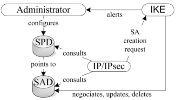
When two hosts share an IPsec SA, their kernels maintain records in two databases:
• Security Association Database: This database contains
all parameters related to each SA and is consulted in order to know how to process each packet (in and out).
• Security Policy Database: This database is established and maintained by a user, an administrator or an appli-cation and describes the security policy to apply to each packet.
When the MN moves between ARs, it is necessary to re-establish the IPsec SAs with the nAR. Hence, a first step is to transfer these two databases from the previous AR to the new one. However, generally ISPs set up an identical security policy (SPD) on all their ARs since it is possible to use wild-cards or ranges for IP addresses. Hence, the SPD context will not always need to be transferred. A second step is to transfer the IKE context. IKE performs mutual authentication between two parties. It uses a shared secret information to efficiently establish IPsec ESP SA and/or IPsec AH SA and negociates a set of cryptographic algorithms to be used by the SAs to protect the traffic that they carry. IKE is combination of the Internet Security Association and Key Management Protocol (ISAKMP) [18], Oakley [19], and SKEME [20] key exchange protocols. ISAKMP is a key exchange independent framework for authentication, SA management and establishment, but it doesn’t define them. Oakley defines series of key exchanges and services provided by each of them. SKEME defines a key exchange which provides anonymity, repudiability, and fast key refreshment. The IKE exchange is divided into two phases:
• Phase 1 is where the two ISAKMP peers establish a se-cure, authenticated channel with which to communicate. This is called the ISAKMP Security Association,
• Phase 2 is where IPsec SAs are negotiated. It provides key material and/or parameters negotiation.
Figure 3 schematizes the relations between SAD and SPD as well as the implication of IKE.
Fig. 3. IPsec processing
Our paper aims to complete previous works ([8][9][10]) on IPsec context transfer (see section III) since only IPsec SA, i.e. SAD context, are transfered. We define the whole definition of the IPsec context as it could be transferred with our implementation, i.e.:
• the SAD context,
• the SPD context and
• the IKE context.
A security association in SAD can be set up either manually or dynamically using IKE. Manual IPsec is useful when no key management solution (e.g. IKE) is available. Both SAD and SPD on each peers have to be configured. But this case is limited both in security and scalability. Dynamic management of the IPsec parameters is a scalable solution: peers do not need to know each other in advance and only security policy i.e. the SPD has to be configured on each them. However, the key management daemon has to run on the peers.
We split our work into two parts: a first one where only SAD context and SPD context need to be transferred and a second one where IKE context need to be transferred too. A. IPsec Security Associations manually set up
In this case, we assume that IPsec SAs are set up without using IKE. Therefore, it is necessary to move data related to these SAs contained in the SAD and the policy applied to these SAs contained in the SPD from the pAR to the nAR. Then, it will be necessary to update the SAD and the SPD on the MN and to configure them on the nAR.
1) SAD context: In the SAD, each SA is identified thanks to the following selectors:
• Destination IP address: IPv6 address of the destination host (MN or AR).
• Source IP address: source IPv6 address of the host (MN or AR).
• IPsec Protocol: (AH or ESP)
• SPI10: value used to distinguish among different SAs terminating at the same destination and using the same IPsec protocol.
In the case of bi-directional communications, we have two entries in the SAD (inbound and outbound). An entry consists of the following field:
10Security Parameter Index
• Sequence Number counter: value used to generate the sequence number in AH or ESP field.
• Anti-replay window: 32-bit counter and bitmap used to bypass replayed packet.
• AHauthentication algorithms and keys.
• ESPencryption algorithms, authentication algorithms and keys.
• Mode: transport or tunnel mode. • Path MTU
• Lifetime of the SA: indicates the lifetime of the SA and if it must be replaced at termination. This lifetime has two forms: a time interval and a bytes count which measures the number of bytes that have been protected by this SA. The first of both which expires close the SA.
All the above selectors and parameters define the SAD context. After the MN’s handover, its SAD must be updated and the nAR’s one must be configured.
Destination SPI Entry Inbound pSA MN pIP@ spi-mn-in SA1 Inbound nSA MN nIP@ spi-mn-in SA1 Outbound pSA pAR IP@ spi-mn-out-1 SA2 Outbound nSA nAR IP@ spi-mn-out-2 SA2
TABLE I
SECURITYASSOCIATIONDATABASE OFMN
Destination SPI Entry Inbound SA nAR IP@ spi-mn-in SA2 Outbound SA MN nIP@ spi-mn-out-2 SA1
TABLE II
SECURITYASSOCIATIONDATABASE OF NAR
Table I shows what must be updated in the MN’s SAD whereas table I describes the desired SAD at nAR. However, several points can turn out to be problematic:
• An SPI collision can occur when pAR’s SAD is trans-ferred to the nAR: the SPI used by the pAR for the outbound SA (spi-mn-out-1) can be already used by the nAR. In this case, it is necessary to modify it (spi-mn-out-2). A solution for this problem using CXTP is proposed in the section VI-C.
• During the MN’s handover, packets coming from the MN towards the pAR can be lost, which leads to an inconsistency between the transferred sequence counter (pAR’s one) and the real counter. Nevertheless, this problem exists only if the difference between these two counters is higher than the anti-replay window.
2) SPD context: In the SPD, selectors used to apply security policy are:
• Inner destination IP address: ultimate IPv6 destination
address for the packet.
• Inner source IP address: ultimate IPv6 source address for the packet.
• Upper protocol: upper layer protocol that must be pro-tected.
Obviously, the security policy associated with the SAs will be transferred in addition to these selectors. It contains:
• Outer IP addressesin tunnel mode case: IPv6 addresses of the IPsec SA endpoints, i.e. hosts addresses between which the security policy has to be applied.
• Policy type: policy to apply to packets, i.e. IPSEC, DISCARD, or NONE.
• Direction: direction of packets, i.e. INBOUND or OUT-BOUND.
• IPsec protocol: AH or ESP. • Mode: transport or tunnel. • Lifetime: policy’s lifetime.
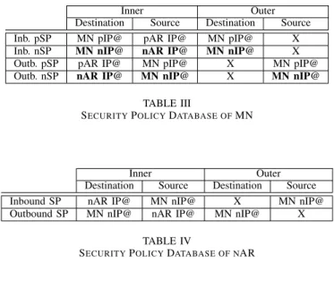
After MN’s handover, its SPD must be updated and the nAR’s one must be configured. In transport mode, only inner IP addresses have to be modified since it has no outer IP addresses. As we are in tunnel mode, we have to modify not only the outer IP addresses but also the inner IP addresses which change during the handover. In our case, there is only the MN’s inner address to modify since the other is the HA IP address which is fixed. Modifications to be done are respectively presented by tables III and IV.
Inner Outer
Destination Source Destination Source Inb. pSP MN pIP@ pAR IP@ MN pIP@ X Inb. nSP MN nIP@ nAR IP@ MN nIP@ X Outb. pSP pAR IP@ MN pIP@ X MN pIP@ Outb. nSP nAR IP@ MN nIP@ X MN nIP@
TABLE III
SECURITYPOLICYDATABASE OFMN
Inner Outer
Destination Source Destination Source Inbound SP nAR IP@ MN nIP@ X MN nIP@ Outbound SP MN nIP@ nAR IP@ MN nIP@ X
TABLE IV
SECURITYPOLICYDATABASE OF NAR
B. IPsec Security Associations dynamically set up using IKE Here, the aim is to transfer IPsec context without having to start IKE from the beginning after a handover. As for the case where SAs are manually set up, the security policy associated with the SAs must be transferred from the pAR to the nAR. They must be updated on the MN and they must be configured on the nAR (see V-A2). Moreover, IKE’s parameters for these SAs must also be transferred.
1) IKE context: As previously mentioned, the IKE ex-change is divided into two phases:
Phase 1: ISAKMP SAs negociation, i.e. the following at-tributes:
• Initiator’s cookiewhich identifies the initiator of the IKE exchange,
• Responder’s cookiewhich identifies the responder of the IKE exchange,
• Encryption algorithm,
• Hash function,
• Authentication method,
• Diffie-Hellman mathematic group,
The initiator’s cookie and responder’s cookie identify a unique ISAKMP SA. Other attributes define the cryptographic algo-rithms to use for this ISAKMP SA. In addition, keys protecting phase 2 exchanges are negociated :
• SKEYIDe (encryption key) which is the keying material
used by the ISAKMP SA to protect the confidentiality of its messages,
• SKEYIDa (authentication key)which is the keying
mate-rial used by the ISAKMP SA to authenticate its messages,
• SKEYIDd (derivation key) which is the keying material
used to derive keys for IPsec SAs.
These keys are derived from a pre-shared key (IKE-PSK) previously installed in the peers. All these parameters are needed by the nAR if the ISAKMP SA has to be refreshed after a handover.
Phase 2: IPsec SAs negociation. The KEYMATi keys (i being
the number of negociated IPsec SAs) derive from SKEYIDd.
They are used by IPsec SAs to authenticate (with AH) or to encrypt (with ESP) MN-AR traffic.
It could be sufficient to transfer only phase 2 result, i.e. only parameters characterizing IPsec SAs. This case is similar to transferring the SAD context as explained in section V-A1. Nevertheless, after the MN’s handover, it would be impossible to start IKE again, for parameters which are needed to con-figure ISAKMP SAs (i.e. used by phase 1) are not transferred to the nAR. Therefore, it would also be interesting to transfer the result from phase 1, i.e. ISAKMP SAs.
Therefore, the IPsec context is composed of SAD’s data, SPD’s data and informations obtained from IKE phase 1. Gains using context transfer for IPsec are:
• Reauthentication signalisation after an handover is not necessarily needed,
• If IKE is used, there is no computation time for IPsec SAs keys or ISAKMP session keys, since previous ones are reused. Note that it is possible to refresh them after the MN’s handover.
VI. IMPLEMENTATION OFCXTPFORIPSEC IN ANIPV6
MOBILITY ENVIRONMENT
In this section we propose an implementation of CXTP to ascertain the validity of the IPsec context presented in this article and we explain the steps to transfer it using CXTP. At the current status of implementation, we transfer only static SAs, i.e. SAs manually set up, so IKE is not required.
A. Platform description and assumptions
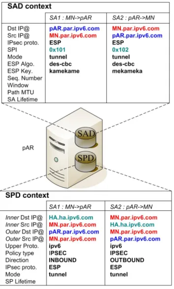
Our platform (see figure 4) is made of four stations running FreeBSD 5.4: 1 MN, 2 ARs and 1 HA. We use a KAME snap to support Mobile IPv6. Both pAR and nAR are connected to the Internet and to the HA. Initially, the MN is connected to the pAR and his traffic is protected by an IPsec tunnel using ESP. Inner headers contains MN’s Co@ and HA’s IP address and outer headers contains MN’s Co@ and AR’s IP address.
Fig. 4. Local platform
The network address plan is the following:
• MN’s Co@ : MN.par.ipv6.com • pAR’s IP@ : pAR.par.ipv6.com • nAR’s IP@ : nAR.nar.ipv6.com
• HA’s IP@ : HA.ha.ipv6.com
Before the handover, MN’s IPsec databases are configured with the following parameters:
#### SPD configuration ####
spdadd MN.par.ipv6.com HA.ha.ipv6.com ipv6 -P out ipsec esp/tunnel/MN.par.ipv6.com-pAR.par.ipv6.com/require; spdadd HA.ha.ipv6.com MN.par.ipv6.com ipv6 -P in ipsec esp/tunnel/MN.par.ipv6.com-pAR.par.ipv6.com/require; #### SAD configuration ####
add MN.par.ipv6.com pAR.par.ipv6.com esp 0x101 -m tunnel
-E des-cbc "kamekame";
add pAR.par.ipv6.com MN.par.ipv6.com esp 0x102 -m tunnel
-E des-cbc "mekameka";
The SPD configuration code indicates that a tunnel protected by ESP is required between the MN (MN.par.ipv6.com) and the pAR (pAR.par.ipv6.com) in both direction (in and out) for the MN-HA traffic.
The SAD configuration code defines the two IPsec SAs needed by the SPD to establish the IPsec tunnel for each direction:
• MN to pAR security association uses des-cbc as
encryp-tion algorithm, kamekame as pre-shared key, and SPI number 0x101,
• pAR to MN security association uses des-cbc as
encryp-tion algorithm, mekameka as pre-shared key, and SPI number 0x102.
Note that with this SPD, MIPv6 signalisation is not protected by the IPsec tunnel. For clarity reasons, we do not expose parameters required to do it. We can see an advantage to secure the MN’s traffic until ARs rather than secure the traffic until the HA: the HA has not to support the cryptographic charge of the whole traffic for all handled MNs but only the cryptographic charge of MIPv6 signalisation. Hence, the cryptographic charge of the whole traffic is distributed among ARs. However, this situation is only possible when the MN trust the visited network and when the HA is in this network. If it is not the case, MN and HA should secure MIPv6 signalisation.
The pAR’s IPsec databases are configured with the follow-ing parameters:
#### SPD configuration ####
spdadd MN.par.ipv6.com HA.ha.ipv6.com ipv6 -P in ipsec esp/tunnel/MN.par.ipv6.com-pAR.par.ipv6.com/require; spdadd HA.ha.ipv6.com MN.par.ipv6.com ipv6 -P out ipsec esp/tunnel/MN.par.ipv6.com-pAR.par.ipv6.com/require; #### SAD configuration ####
add MN.par.ipv6.com pAR.par.ipv6.com esp 0x101 -m tunnel
-E des-cbc "kamekame";
add pAR.par.ipv6.com MN.par.ipv6.com esp 0x102 -m tunnel
-E des-cbc "mekameka";
Figure 5 shows the IPsec context (i.e. SAD and SPD contexts) set up by the pAR’s IPsec configuration code. After the transfer to the nAR, it is configured according to the tables II and IV.
The CTAR message sent by the MN must not be protected by IPsec. Otherwise ,the AR which will receive these messages will not be capable of decrypting them and CXTP will not work. To solve this problem, we could even use link local addresses (of MN and AR) - but only if MN is one hop from AR - or modify the security policy to bypass CXTP messages. B. Implementation modules
The implementation (see figure 6) is divided into two modules. A first one, named CXTP module which follows the guidelines from RFC 4067 (CXTP [13]) and another one, named IPsec CXTP module which links the CXTP module with the FreeBSD kernel’s IPsec databases. These modules in-tercommunicate through a shared memory where the contexts are stored. This is done to guarantee that CXTP can work with every kind of context, not only with IPsec context.
CXTP module can be used in both the predictive and reactivemode. Therefore, the context can be transferred before or after the MN’s handover. This module is able:
• to be triggered by a MN or by the network,
• to get a context from a shared memory, • to transfer contexts between two ARs, • and to put a context into a shared memory.
This module should be installed in MN and ARs.
IPsec CXTP module uses PF KEY Key Management API11[21] to communicate with the kernel. However, this API
Fig. 5. SAD and SPD context on the pAR
Fig. 6. Implementation architecture
only specifies messages to manage the SAD in the kernel. Hence, we had to use PF KEY extensions for IPsec Policy Management integrated in KAME stack [22].
At this time, the module is able:
• to get an SAD context from a shared memory or from kernel’s SAD,
• to configure IP addresses and SPI of SAD context, • to get an SPD context from a shared memory or from
kernel’s SPD,
• to configure inner and outer IP addresses of SPD context, • and to put the modified contexts into the kernel’s
databases or into a shared memory. This module should be installed in ARs only. C. Procedure to perform an IPsec context transfer
Context transfer can be perfomed before or after a handover, iniated by the MN or by the network. In order to illustrate how the implementation works, we choose the predictive mode initiated by the MN case. Hence, respecting figure 1, the procedure to perform an IPsec context transfer with our implementation is as follows:
1) The MN is connected to the pAR and sends a CTAR message.
2) On the pAR: CXTP module informs IPsec CXTP module to get SAs associated with the MN from the kernel’s SAD and SPD, to put them into shared memory and to delete them from kernel. The MN IP address is used to identify these SAs. CXTP module gets the context from the shared memory and transfers it to the nAR using a CTDmessage.
3) On the nAR: CXTP module gets the CTD message, sends a CT-Reply message to the pAR and waits a CTAR message from the MN.
4) The MN performs a handover between pAR and nAR and sends a CTAR to the nAR. In the same time, it updates its SAD and SPD with its new Co@ and nAR’s IP address.
5) On the nAR: CXTP module puts contexts into shared memory and informs IPsec CXTP module to configure it, i.e. to modify MN’s pCo@ with new one and to update pAR IP address with nAR’s one. If the SPI is already used, the pAR could send a CTAA message carrying a new SPI, but this solution is not implemented yet. After contexts configuration, IPsec CXTP module installs them into the kernel’s SAD and kernel’s SPD. 6) The MN has access to the network again.
This solution could be used while the MN stays in the same authentication domain (e.g. ISP network) and until the SA’s lifetime expires. However, interactions with authentication frameworks are out of scope of this paper and left for further studies.
VII. CONCLUSION& FUTURE WORK
This paper set out the context transfer mechanism and a possible application for IPsec. This mechanism can offer
performance improvements for IPv6 mobility environment while guaranteeing an unchanged security level. That is why in practice, we tried to apply it to IPsec in two steps: first of all by defining the IPsec context, then by explaining how to use CXTPin order to transfer IPsec related information. We wrote an implementation of a module to transfer generic contexts and an implementation of an other module to get, to update and to reinstall IPsec SAs into the FreeBSD kernel. However, the last module is not yet complete: IKE context (using racoon12) can
not be transferred for the moment: this is a next step for our implementation. In the same time, we will investigate CXTP for IPsec version 2 [23] and in particular IKEv2 [24]. This new IPsec version comes with a lot of changes that will modify our implementation, in particular because of the new Peer Authentication Database (PAD) which provides a link between an SA management protocol (such as IKE) and the SPD. Last but not least we will simulate this mechanism to measure performances benefits during handovers but also in order to compare it with other solutions such as pre-authentication [25]. These studies could help to apply the context transfer mechanism to HA reliability problem [26] or IPsec failover problem [27], both currently under study at IETF.
VIII. ACKNOWLEDGMENT
The authors would like to thank Tony CHENEAU for his contribution to the IPsec context transfer implementation during his work experience at France T´el´ecom R&D.
REFERENCES
[1] I. C. Society, “IEEE std 802.11i: Amendment 6: Medium Access Control (MAC) Security Enhancements,” July 2004.
[2] S. Kent and R. Atkinson, “Security Architecture for the Internet Proto-col,” Internet Engineering Task Force, RFC 2401, November 1998. [3] C. Rigney, S. Willens, A. Rubens, and W. Simpson, “Remote
Authen-tication Dial In User Service (RADIUS),” Internet Engineering Task Force, RFC 2138, June 2000.
[4] P. Calhoun, J. Loughney, E. Guttman, G. Zorn, and J. Arkko, “Diameter Base Protocol,” Internet Engineering Task Force, RFC 3588, September 2003.
[5] M. Georgiades, N. Akhtar, C. Politis, and R. Tafazolli, “Enhancing mobility management protocols to minimise AAA impact on handoff performance,” in Computer Communications, vol. 30. Butterworth-Heinemann, February 2007, pp. 608–618.
[6] M. Georgiades, H. Wang, and R. Tafazolli, “Security of Context Transfer in Future Wireless Communications,” in 2006 international conference on Communications and mobile computing (IWCMC 2006). Vancouver, British Columbia, Canada: ACM Press, July 2006, pp. 389–394. [7] M. Kassab, A. Belghith, J.-M. Bonnin, and S. Sassi, “Fast
Pre-Authentication Based on Proactive Key Distribution for 802.11 Infras-tructure Networks,” in 1st ACM International Workshop on Wireless Multimedia Networking and Performance Modeling (WMuNeP 2005), Montreal, Canada, October 2005.
[8] L.-N. Hamer, P. Hazy, R. G. L, G. Krishnamurthi, and S. Sengodan, “Is-sues in IPsec Context Transfer,” draft-gopal-seamoby-ipsecctxt-is“Is-sues, Internet Engineering Task Force, Internet Draft, February 2002. [9] R. Gopal, V. Devarapalli, G. Krishnamurthi, R. Koodli, S. Sengodan,
and C. Perkins, “IPsec Context Transfer,” draft-gopal-seamoby-ipsec-relocate, Internet Engineering Task Force, Internet Draft, November 2001.
[10] L.-N. Hamer and B. Kosinski, “IPsec Context Transfer,” draft-hk-seamoby-ct-ipsec, Internet Engineering Task Force, Internet Draft, May 2001.
12Key management daemon for IKE
[11] J. Bournelle, M. Laurent-Maknavicius, H. Tschofenig, and Y. E. Mgha-zli, “Handover-aware Access Control Mechanism: CTP for PANA,” in 3rd European Conference on Universal Multiservice Networks (ECUMN 2004), Porto, Portugal, October 2004.
[12] D. Forsberg, Y. Ohba, B. Patil, H. Tschofenig, and A. Yegin, “Protocol for Carrying Authentication for Network Access (PANA),” draft-ietf-pana-pana, Internet Engineering Task Force, Internet Draft, Decembre 2006.
[13] J. Loughney, M. Nakhjiri, C. Perkins, and R. Koodli, “Context Transfer Protocol (CXTP),” Internet Engineering Task Force, RFC 4067 (Exper-imental), July 2005.
[14] J. Kempf, “Problem Description: Reasons For Performing Context Transfers Between Nodes in an IP Access Network,” Internet Engineer-ing Task Force, RFC 3374 (Informational), September 2002.
[15] S. Kent and R. Atkinson, “IP Authentication Header (AH),” Internet Engineering Task Force, RFC 2402, November 1998.
[16] ——, “IP Encapsulating Security Payload (ESP),” Internet Engineering Task Force, RFC 2406, November 1998.
[17] D. Harkins and D. Carrel, “The Internet Key Exchange (IKE),” Internet Engineering Task Force, RFC 2409, November 1998.
[18] D. Maughan, M. Schertler, M. Schneider, and J. Turner, “Internet Se-curity Association and Key Management Protocol (ISAKMP),” Internet Engineering Task Force, RFC 2408, November 1998.
[19] H. Orman, “The OAKLEY Key Determination Protocol,” Internet En-gineering Task Force, RFC 2412, November 1998.
[20] I. C. Society, “SKEME: A Versatile Secure Key Exchange Mechanism for Internet,” in IEEE Proceedings of the 1996 Symposium on Network and Distributed Systems Security, 1996.
[21] D. McDonald, C. Metz, and B. Phan, “PF KEY Key Management, API Version 2,” Internet Engineering Task Force, RFC 2367, July 1998. [22] S. Sakane, PF KEY Extensions for IPsec Policy Management in KAME
Stack, KAME Project, December 2002.
[23] S. Kent and K. Seo, “Security Architecture for the Internet Protocol,” Internet Engineering Task Force, RFC 4301, December 2005. [24] C. Kaufman, “Internet Key Exchange (IKEv2) Protocol,” Internet
Engi-neering Task Force, RFC 4306, December 2005.
[25] A. Dutta, V. Fajardo, Y. Ohba, K. Taniuchi, and H. Schulzrinne, “A Framework of Media-Independent Pre-Authentication (MPA),” draft-ohba-mobopts-mpa-framework, Internet Engineering Task Force, Inter-net Draft, March 2007.
[26] R. Wakikawa, “Home Agent Reliability Protocol,” draft-ietf-mip6-hareliability, Internet Engineering Task Force, Internet Draft, March 2007.
[27] V. Narayanan, “IPsec Gateway Failover and Redundancy - Problem Statement and Goals,” draft-vidya-ipsec-failover-ps, Internet Engineer-ing Task Force, Internet Draft, December 2006.