HAL Id: hal-00998512
https://hal.archives-ouvertes.fr/hal-00998512
Submitted on 2 Jun 2014
HAL is a multi-disciplinary open access
archive for the deposit and dissemination of
sci-entific research documents, whether they are
pub-lished or not. The documents may come from
teaching and research institutions in France or
abroad, or from public or private research centers.
L’archive ouverte pluridisciplinaire HAL, est
destinée au dépôt et à la diffusion de documents
scientifiques de niveau recherche, publiés ou non,
émanant des établissements d’enseignement et de
recherche français ou étrangers, des laboratoires
publics ou privés.
Polarization Synthesis of Arbitrary Arrays with Shaped
Beam Pattern
Benjamin Fuchs
To cite this version:
Benjamin Fuchs. Polarization Synthesis of Arbitrary Arrays with Shaped Beam Pattern. IEEE
International Symposium on Phased Array Systems & Technology, 2013, 2013, pp.689-692.
�10.1016/j.jece.2014.01.002�. �hal-00998512�
Polarization Synthesis of Arbitrary Arrays
with Shaped Beam Pattern
Benjamin Fuchs
University of Rennes 1 / IETR35042 Rennes, France
Email: [email protected]
Abstract—The joint synthesis of the spatial power pattern and polarization of arbitrary arrays is addressed. Specifically, the element excitations are determined such that the array radiates a shaped power pattern while its polarization is optimized in an angular region. Any state of polarization (elliptical, circular and linear) can be synthesized and there is no restriction regarding the array geometry and element patterns. The synthesis problem is rewritten as a convex optimization problem, that is efficiently solved using readily available software. Various numerical results are presented to validate the proposed method and illustrate its potentialities.
I. INTRODUCTION
The synthesis of shaped beams with antenna arrays is a problem having many applications in radar, remote sensing and communication systems [1], [2]. On top of controlling the spatial power radiated by the array, optimizing the waveform polarization is also of uppermost interest. It enables for in-stance to improve the performances of active sensing [3] and communication systems [4], [5]. For instance, the generation of a shaped beam with a given polarization is a frequently encountered requirement for spatial applications. Thus, LEO satellite antenna shall provide an isoflux coverage of the earth surface with a circular polarization over a wide angular range [6].
The polarization synthesis of arrays with focused beam pat-terns has been addressed in [7], [8]. In these papers, the joint synthesis of the focused beam pattern and the polarization is formulated as a convex optimization problem, which ensures the optimality of the obtained solution.
The synthesis of shaped beams is a more difficult problem since it is not convex in the general case. However, an iterative algorithm has been recently proposed in [9] to synthesize shaped beams in which each step is reduced to a simple convex optimization problem.
In this paper, the methods detailed in [8] and [9] are combined to synthesize arrays radiating a shaped beam with an optimized polarization. The proposed algorithm consists in solving a sequence of convex optimization problems. It can thus be readily implemented using freely accessible routines.
The paper is organized as follows. In Section II, the synthesis problem is described and the resolution method is detailed. The proposed method is then applied in Section III to show its interest and efficiency. Conclusions are drawn in Section IV.
II. ARRAYSYNTHESISPROBLEM
A. Antenna Array
Let us consider an antenna array composed ofN elements placed at arbitrary but known locations ⃗ri withi = 1, ..., N .
The problem is described for a one-dimensional pattern syn-thesis without loss of generality. This synsyn-thesis is performed over the polar angleθ in a fixed azimuthal plane φ = φ0, that
is omitted in the notations. The extension to a two-dimensional (2-D) pattern synthesis, i.e. a synthesis over both angular directions θ and φ, is straightforward.
The array factor g(θ) in the direction θ is: g(θ)H= [e−jk⃗r1.ˆr(θ)
· · · e−jk⃗rN.ˆr(θ)], (1)
where .H denotes the Hermitian transposition, k is the free
space wave number andˆr(θ) is the unit vector in the direction θ (and azimuthal plane φ0).
The element i of the array radiates a vectorial far field pattern which has, in general, both a θ and φ component: (fθ i(θ), fφi(θ)). This yields the following vectorial antenna
array responses: {
aθ(θ)H= [fθ 1(θ)e−jk⃗r1.ˆr(θ)· · · fθ N(θ)e−jk⃗rN.ˆr(θ)]
aφ(θ)H= [fφ1(θ)e−jk⃗r1.ˆr(θ)· · · fφN(θ)e−jk⃗rN.ˆr(θ)]
(2) The electric field radiated by the array is:
E(θ) = [ Eθ(θ) Eφ(θ) ] = [ aθ(θ)Hw aφ(θ)Hw ] , (3)
where w is theN -dimensional vector of complex (amplitude and phase) element excitations. The excitation vector w is thus composed ofN scalars wi that control the vectorial field E(θ)
radiated by the array. These complex excitations wi are the
unknowns to determine. B. Array Pattern Synthesis
The array pattern synthesis problem amounts to find the excitations w in (3) to achieve a pattern that has both spatial power and polarization requirements. Specifically, the goal is to synthesize a pattern having:
• a shaped beam, i.e. a power pattern close to a desired shaped(θ) over an angular region SB,
• sidelobes below a given upper boundρ(θ) over SL, • a wave polarization characterized by (γ0, δ0) over
These requirements can be written: sup θ∈SB |E(θ)| 2 − d(θ) ≤ ϵsb(θ) |E(θ)|2≤ ρ(θ), ∀ θ ∈ SL Eφ(θ) − γ0ejδ0Eθ(θ) ≤ ϵpol(θ), ∀ θ ∈ POL . (4)
In the first constraint, the maximum “distance” between the targeted shaped(θ) and the power radiated by the array |E(θ)|2 is bounded by ϵsb(θ). The accuracy of the polarization is
guaranteed via the third constraint of (4) which amounts to keep under control the ratio between the two components of the field:Eφ(θ) and Eθ(θ). When (γ0, δ0) = (1, ±π/2), i.e. when
|Eφ(θ) ± jEθ(θ)| is upper bounded or minimized, a circular
polarization is synthesized. More details about this formulation can be found in [8].
Using (3), the synthesis problem can be expressed: find w such as the constraints: sup θ∈SB wH[a θ(θ) + aφ(θ)][aθ(θ) + aφ(θ)]Hw− d(θ) · · · · · · ≤ ϵsb(θ) [aθ(θ) + aφ(θ)]Hw ≤√ρ(θ), ∀ θ ∈ SL [aφ(θ) − γ0ejδ0aθ(θ)]w ≤ ϵpol(θ), ∀ θ ∈ POL . (5) are satisfied.
This method can easily be adapted to optimize the polarization radiated by the array while the shaped beam is upper and lower bounded byu(θ) and l(θ) respectively. The synthesis problem becomes:
min
w ϵpol under (5),
whereϵsb(θ) = (u(θ) − l(θ))/2 and d(θ) = (u(θ) + l(θ))/2.
C. Resolution Method
To solve the synthesis problem (5), the regions SB, SL and POL are sampled in θk, θm and θq directions, respectively.
Let us introduce the following notations: aθ i= aθ(θi), aφi=
aφ(θi), dk = d(θk) and ρm= ρ(θm). The constraints (5) can
then be rewritten: max k=1,...,K wH[aθ k+ aφk][aθ k+ aφk]Hw− dk ≤ ϵsb(θk), [aθ m+ aφm]Hw ≤√ρm, for m = 1, ..., M [aφq− γ0e jδ0a θ q]w ≤ ϵpol(θq), for q = 1, ..., Q . (6) The first constraint of (6) is equivalent to:
max k=1,...,K wHl [aθ k+ aφk][aθ k+ aφk]Hwr− dk ≤ ϵsb(θk), (7) with wl= wr.
Then, if the vector wl or wr in (6) is alternatively fixed, the
constraints become linear with respect to the other vector. By fixing wl for instance, the N dimensional vector cHk =
wH
l [aθ k + aφk][aθ k+ aφk]H is constant and the problem to
solve amounts to find wr such that:
max k=1,...,K cHkwr− dk ≤ ϵsb(θk), [aθ m+ aφm]Hwr ≤√ρm, form = 1, ..., M [aφq− γ0e jδ0a θ q]wr ≤ ϵpol(θq), for q = 1, ..., Q . (8)
This optimization problem is convex and therefore can be efficiently solved optimally using readily available routine such as Sedumi [10].
To ensure the equivalence between the convex set of con-straints (8) and the initial ones (6), wrmust be equal to wlas
written in (7).
To achieve this goal, an iterative scheme inspired from [11] and detailed in [9] is proposed. This algorithm generally converges to a good solution w that satisfies (6).
III. NUMERICALRESULTS
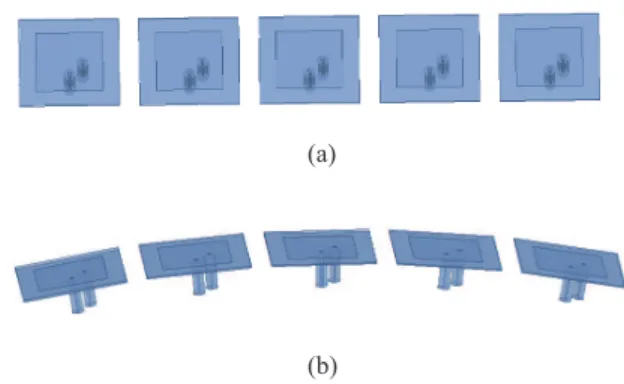
The synthesis of shaped beams with optimized circular polarization is presented for two configurations: a linear and a conformal array of patches that are represented in Fig. 1. Each square patch is fed by two coaxial probes iX and iY and is therefore dually polarized. The active element pattern method [12] is applied to calculate the pattern of the fully excited array. Each patch is simulated in the array environment with a full wave numerical software (Ansoft HFSS) to provide the array response aθ(θ) and aφ(θ) of (2). Using this method enables
one to take the mutual coupling effects into account.
(a)
(b)
Fig. 1. Geometry of the array composed of five dual polarized patches: (a) top view of the linear array and (b) side view of the conformal array.
A. Linear Array of Patches
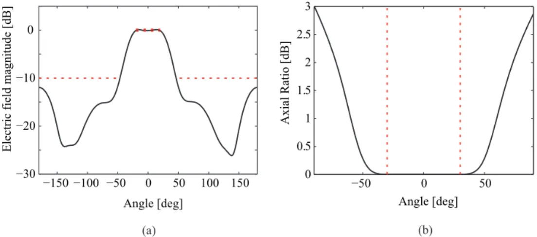
The synthesis problem amounts to find the excitationsiX and iY (for i + 1, ..., 5) of the linear array represented Fig. 1(a) such as it radiates:
• a sectoral shaped beam of ripple ±0.2 dB over SB=[−20◦, 20◦]
• sidelobes belowρ =-10 dB over SL=[−180◦, −50◦]∪
[50◦, 180◦]
• an optimized circular polarization over POL=[−30◦, 30◦].
The optimized far field patterns and axial ratio are plotted in Fig. 2 whereas the corresponding excitations are reported in Table I. The spatial power requirements are satisfied and the axial ratio is very close to 0 dB in the region of interest, which shows the good quality of the circular polarization.
B. Conformal Array of Patches
An array of five patches that are conformed on a cylinder, as represented in Fig. 1(b), is considered. The synthesis
TABLE I. OPTIMIZED EXCITATIONS OF THE LINEAR ARRAY SYNTHESIS PROBLEM feed |w| ∠w [deg] 1X 1.00 -74 1Y 0.95 -164 2X 0.26 85 2Y 0.21 163 3X 0.17 -29 3Y 0.16 -121 4X 0.25 -97 4Y 0.21 -20 5X 0.15 160 5Y 0.14 -114
TABLE II. OPTIMIZED EXCITATIONS OF THE CONFORMAL ARRAY SYNTHESIS PROBLEM feed |w| ∠w [deg] 1X 0.32 -165 1Y 0.38 -79 2X 1.00 55 2Y 0.64 171 3X 0.37 -67 3Y 0.45 -1 4X 0.60 175 4Y 0.28 -1 5X 0.30 -18 5Y 0.19 -144
problem consists in finding the excitations iX and iY (for i + 1, ..., 5) of this conformal array, such as it radiates:
• a sectoral shaped beam of ripple ±0.5 dB over SB=[−40◦, 10◦]
• sidelobes belowρ =-10 dB over SL=[−180◦, −60◦]∪
[40◦, 180◦]
• an optimized circular polarization over POL=[−20◦, 0◦].
The optimized far field patterns and axial ratio are plotted in Fig. 3 whereas the corresponding excitations are reported in Table II. While the required sectoral beam pattern is achieved, a circular polarization is achieved in the angular range of interest. As shown in Fig. 3(b), the axial ratio is lower than 0.7 dB over POL.
IV. CONCLUSION
A synthesis method to design arrays that radiate a power pattern, that is both upper and lower bounded, with an op-timized specified polarization over a given angular range, has been proposed. This joint synthesis (shaped beam and polarization) is a requirement often encountered in many applications.
The advantages of the proposed method are manifold. First, there is no restriction regarding the type of array to be synthesized. Second, any state of polarization and shaped beams can be synthesized. Finally, the proposed algorithm can be easily implemented and it only calls for readily available routines.
REFERENCES
[1] O.M. Bucci, G. D’Elia, G. Mazzarella, and G. Panariello, ”Antenna pattern synthesis: A new general approach,” Proc. IEEE, Vol. 82, No. 3, pp.358-371, March 1994.
[2] T. Isernia, O.M. Bucci, and N. Fiorentino, ”Shaped beam antenna synthesis problem: Feasibility criteria and new strategies,” Journal of Electromagnetic Waves and Applications, Vol. 12, pp.103-137, 1998. [3] M. A. Sletten and D. B. Trizna, ”An ultrawideband, polarimetric radar
for the studies of sea scatter” IEEE Trans. on Antennas and Propagation, Vol. 42, no. 11, pp. 1461-1466, Nov. 1994.
[4] M. R. Andrews, P. P. Mitra, and R. De Carvalho, ”Tripling the capacity of wireless communications using electromagnetic polarization,” Nature, vol. 409, pp. 316-318, Jan. 2001.
[5] W. C. Y. Lee and Y. S. Yeh, ”Polarization diversity system for mobile radio,” IEEE Trans. on communications, vol. 26, pp. 912-923, Oct. 1972. [6] R. Ravanelli, C. Iannicelli, N. Baldecchi, and F. Franchini, ”Multi-objective optimization of an isoflux antenna for LEO satellite down-handling link,” Int. Conf. on Microwave Radar and Wireless Communi-cations (MIKON), 2010.
[7] J.-J. Xiao and A. Nehorai, ”Optimal polarized beampattern synthesis using a vector-antenna array,” IEEE Trans. on Signal Processing, Vol. 57, no. 2, pp. 576-587, Feb. 2009.
[8] B. Fuchs and J.J. Fuchs, ”Optimal polarization synthesis of arbitrary arrays with focused power pattern,” IEEE Trans. on Antennas and Propag., vol. 59, no. 12, pp.4512-4519, Dec. 2011.
[9] B. Fuchs, A. Skrivervik, and J. R. Mosig, ”Shaped Beam Synthesis of Arbitrary Arrays via Sequential Convex Optimizations,” IEEE Trans. on Antennas and Propag., under review.
[10] SeDuMi, http://sedumi.ie.lehigh.edu/
[11] J. Wang, Q. Zhang, L. Ljung, “Revisiting the Two-Stage Algorithm for Hammerstein System Identification,” Joint 48th IEEE Conference on Decision and Control and 28th Chinese Control Conference, Shanghai, P.R. China, Dec. 2009.
[12] D. F. Kelley and W. L. Stutzman, ”Array antenna pattern modeling methods that include mutual coupling effects,” IEEE Transactions on Antennas and Propagation, vol. 41, no. 12, pp.1625-1632, Dec. 1993.
−50 0 50 0 0.5 1 1.5 2 2.5 3 Angle [deg] Axial Ratio [dB] −150 −100 −50 0 50 100 150 −30 −20 −10 0 Angle [deg]
Electric field magnitude [dB]
(a) (b)
Fig. 2. Synthesis results of the linear array composed of five patches: (a) shaped far field radiation pattern and (b) optimized axial ratio.
−150 −100 −50 0 50 100 150 −30 −20 −10 0 Angle [deg]
Electric field magnitude [dB]
−50 0 50 0 0.5 1 1.5 2 2.5 3 Angle [deg] Axial Ratio [dB] (a) (b)