HAL Id: hal-02149492
https://hal.archives-ouvertes.fr/hal-02149492
Submitted on 7 Jul 2020
HAL is a multi-disciplinary open access
archive for the deposit and dissemination of
sci-entific research documents, whether they are
pub-lished or not. The documents may come from
teaching and research institutions in France or
abroad, or from public or private research centers.
L’archive ouverte pluridisciplinaire HAL, est
destinée au dépôt et à la diffusion de documents
scientifiques de niveau recherche, publiés ou non,
émanant des établissements d’enseignement et de
recherche français ou étrangers, des laboratoires
publics ou privés.
ISSN Online: 2152-2308 ISSN Print: 2152-2294
DOI: 10.4236/wet.2019.102002 Mar. 6, 2019 19 Wireless Engineering and Technology
Design of Printed Dipole Array for
Omnidirectional Radiation Pattern
Jean-Marie Floc’h
IETR, INSA Rennes, Rennes, France
Abstract
In this paper, we describe 2 kinds of printed dipole arrays and compare the performances of these arrays in term of reflexion coefficient, radiation pat-tern and dimensions. It is interesting to design array in order to obtain better performances in term of omnidirectional radiation pattern in comparison with single element. We choose this elementary source in order to obtain compact array with good performances. These antenna arrays are designed to have omnidirectional radiation pattern with horizontal polarization. We present an application dedicated to compact base station in the last section.
Keywords
Printed Dipole, Dipole Array, Omnidirectionel Radiation Pattern, Horizontal Polarization
1. Introduction
Omnidirectional antennas are very interesting in many applications such as communication systems, base station and sensors [1]-[6]. Specific applications for communication systems could be in rotating structure like airplane engine, wheels and rotating machines.
In the first section, we describe the chosen single element choosing for the ar-rays. After we present two types of printed dipole arrays (3-dipole array and 4-dipole array), the goal is to obtain compact array with good performances in term of radiation pattern and Omni directionality. We then compare the per-formances of the two arrays in term of gain and efficiency. In the last section, we present an application for base station for communication systems with results in simulation and measurements for the 3-dipole array and simulation for the 4-dipole array. For all the radiation measurements, gain and efficiency, we use a Stargate 32 from SATIMO.
How to cite this paper: Floc’h, J.-M. (2019) Design of Printed Dipole Array for Omnidirectional Radiation Pattern. Wireless Engineering and Technology, 10, 19-33. https://doi.org/10.4236/wet.2019.102002 Received: October 1, 2018
Accepted: March 3, 2019 Published: March 6, 2019
Copyright © 2019 by author(s) and Scientific Research Publishing Inc. This work is licensed under the Creative Commons Attribution International License (CC BY 4.0).
http://creativecommons.org/licenses/by/4.0/
DOI: 10.4236/wet.2019.102002 20 Wireless Engineering and Technology
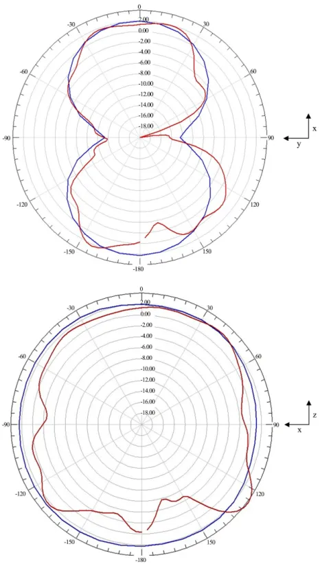
measurement and simulation for both reflection coefficient and radiation pattern. We note also that don’t have good omnidirectional radiation patterns in the horizontal polarization (Figure 3).
We obtain a ripple of ±0.8 dBi in the xoz plane in simulation and much more in measurements.
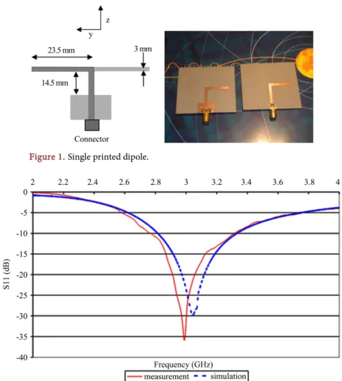
Figure 1. Single printed dipole.
DOI: 10.4236/wet.2019.102002 21 Wireless Engineering and Technology
3. Array of 3 Printed Dipoles
Dipole arrays are interesting if we want better performances in term of omnidi-rectionnality and gain. We compare two potential arrays to be capable to re-spond to this functionality.
Figure 3. Simulated and measured gain in xoy planeand in xoz plane at 3 GHz
DOI: 10.4236/wet.2019.102002 22 Wireless Engineering and Technology
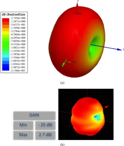
(a)
(b)
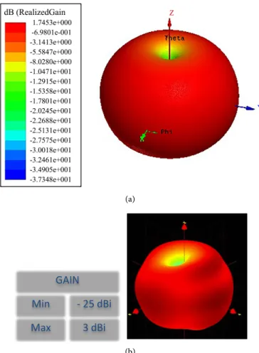
Figure 4. 3D radiation patterns at 3 GHz: (a) Simulation and (b) measurement.
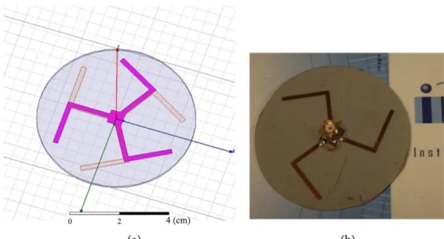
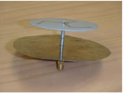
We present this first array in Figure 5. It consist of a circular network of 3 printed dipoles positioned every 120˚. The diameter of the array is 60 mm, the substrate is a Teflon-glass with 2.2 permittivity and a 0.8 mm thickness. The feeding of the proposed array is realized in its center with a SMA connector. The frequency design is around 3 GHz. The dimensions of the dipole are the same that the last section. Like the elementary dipole, the square ground plane where the connector is welded is placed at around λ/4.
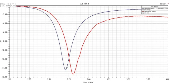
Figure 6 presents the reflection coefficient for simulation (blue) and mea-surements (red). The 3 dipole array radiates at 3 GHz as predicted. The band-width of this array is 230 MHz between 2.85 and 3.08 GHz at S11 less than −10 dB.
The simulated and measured 3D radiation paterns E total are presented in
Figure 7. The axis is z in red, x in green and y in blue. The maximum gain is 1.7 dBi for simulation and 3 dBi for measurements. The measured efficiency at 3 GHz is 85%.
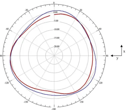
We present in Figure 8 the radiation patterns at 3 GHz for the XOZ and XOY planes. Simulated result is in blue and measured one in red. In the XOY plane, the ripple on the radiation pattern is around ±1.1 dBi.
We note a good agreement between simulation and measurements.
GAIN Min Max
- 25 dBi 2.7 dBi
DOI: 10.4236/wet.2019.102002 23 Wireless Engineering and Technology
4. Dipole Array
The proposed circular 4 dipole array is shown in Figure 9.
In this case, the circular network of 4 printed dipoles are positioned every 90˚. We use the same substrate and the same feeding connector as the 3 dipole array. The dimensions of the dipole are also the same. We place the dipoles at λ/4 from the square ground plane like the 3 dipole array. The diameter of this antenna is also 60 mm. The frequency design of the array is around 3 GHz as it can be con-cluded from the reflection coefficient of the array presented in Figure 10. The measured bandwidth of the array is 190 MHz between 2.7 and 2.89 GHz. We note a reduction of the bandwidth in comparison with the 3 dipole array.
(a) (b)
Figure 5. 3 dipole array: (a) Simulated array and (b) Prototyped structure.
Figure 6. Reflection coefficient of the 3 dipole array.
2.00 2.25 2.50 2.75 3.00 3.25 3.50 3.75 4.00 Freq [GHz] -30.00 -25.00 -20.00 -15.00 -10.00 -5.00 0.00 Y1 reseau3 XY Plot 1 m1 Curve Info dB(St(Rectangle11_T1,Rectangle11_T1)) Setup1 : Sw eep1 dB(St(Port1,Port1)) Import1 : d3 Name X Y m1 2.9800 -14.0861
DOI: 10.4236/wet.2019.102002 24 Wireless Engineering and Technology
(a)
(b)
Figure 7. 3D radiation patterns at 3 GHz: (a) Simulation and (b) Measurement.
GAIN
Min
Max
- 25 dBi
3 dBi
DOI: 10.4236/wet.2019.102002 25 Wireless Engineering and Technology
Figure 8. Radiation patterns in xoz and xoy plane at 3 GHz. Simulation in blue and
mea-surement in red.
(a) (b)
Figure 9. 4 dipole array: (a) Simulated array and (b) Prototyped structure.
The simulated and measured 3D radiation patterns are presented in Figure 11. The maximum gain measured is 1.7 dBi at the 2.7 GHz frequency with a val-ue of 1.4 dBi for simulation. The measured efficiency is 85% at the resonant fre-quency.
The simulated (in blue) and measured red) results of the radiation patterns in xoz and xoy planes are presented in Figure 12. In the xoy plane, the ripple on the radiation pattern is around ±0.25 dBi at 2.7 GHz.
DOI: 10.4236/wet.2019.102002 26 Wireless Engineering and Technology
Figure 10. Reflection coefficient of the 4 dipole array: simulation in blue and measurement in red.
(a)
(b)
Figure 11. 3D radiation patterns for the 4 dipole array: (a) Simulation and (b)
Measurement.
GAIN
Min
Max
- 25 dBi
1.7 dBi
DOI: 10.4236/wet.2019.102002 27 Wireless Engineering and Technology
Figure 12. Radiation patterns in the xoz and xoy plane at 2.7 GHz. Simulation in blue and
measurement in red.
5. Comparison between Gain and Efficiency
In the next section, we compare the maximum gain and the efficiency for the two dipole arrays.
We note a better gain for the 3 dipole with around 3.75 dBi and 2 dBi less for the 4 dipole array as shown in Figure 13.
DOI: 10.4236/wet.2019.102002 28 Wireless Engineering and Technology
Figure 13. Maximum gain in blue for the 4 dipole array and for the 3 dipole array in red.
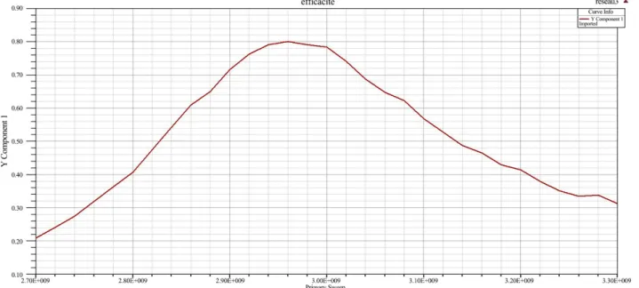
We note in this case efficiencyal most equal for the two arrays with a maxi-mum efficiency around 0.88% for the 3 dipole array as shown in Figure 14.
6. Application for Compact Base Station
In this last section, we propose an application of the 3 dipole array for compact base station. In this application, we put a circular ground plane at 20 mm from the array. The radius of the ground plane is 45 mm. we obtain a very compact base station with a 90 mm diameter with 20.8 mm thickness as shown in the next photos. It will be easy to integrate electronics and battery on the backside of the ground plane and keep a very compact base station.
DOI: 10.4236/wet.2019.102002 29 Wireless Engineering and Technology
Photos of the compact base station.
The next figure presents the S11 in simulation and measurements. We note a reduce bandwidth and a sight degradation of the S11 as shown in Figure 15. The degradation of S11 is due to the presence of the ground plane and the degrada-tion increase when the distance between the ground plane and the array de-crease.
We obtain a measured bandwidth for S11 less than −6 dB of 190 MHz.
We obtain a ripple of ±2 dBi in the xoy plane in measurements as shown in
Figure 16.
We obtain a maximum gain of 3.7 dBi at 3 GHz and the bandwidth at −1 dBi is 190 MHz as shown in Figure 17 and Figure 18.
DOI: 10.4236/wet.2019.102002 30 Wireless Engineering and Technology
DOI: 10.4236/wet.2019.102002 31 Wireless Engineering and Technology
Figure 16. Radiation patterns in the xoz and xoy plane at 3 GHz. Simulation in blue and measurement in red.
(a) (b)
Figure 17. 3D measured radiation patterns (a) at 3000 MHz and (b) 2860 MHz.
Figure 18. Maximum gain for the 3 dipole array with ground plane.
GAIN Min Max - 25 dBi 2.2 dBi GAIN Min Max - 25 dBi 2.55 dBi
DOI: 10.4236/wet.2019.102002 32 Wireless Engineering and Technology
Figure 19. Measured efficiency for the 3 dipole array with ground plane.
Figure 20. Simulated radiation patterns in the xoy plane at 2.76 GHz for the 4 dipole array with ground plane.
7. Conclusions
We present the design of 2 circular dipole arrays in order to obtain omnidirec-tional radiation pattern with horizontal polarization and stable radiation per-formances. We obtain good comparison between simulations and measure-ments.
If we compare the results for the 3 and 4 dipole arrays, The 3-dipole array presents good performances in term of match, bandwidth, gain and efficiency.
DOI: 10.4236/wet.2019.102002 33 Wireless Engineering and Technology
The 4-dipole array presents better performances in term of ripple in the xoy plane. Theses arrays are very compact with a diameter of 60 mm with a thickness of 0.8 mm. We present in the last section an application for compact base station with no degradation in the performances (we introduce a ground plane at 20 mm from the array). The choice is now a question of applications. The potential application of these dipole arrays is compact base station for communication systems and antenna for communication for rotating machine.
Conflicts of Interest
The author declares no conflicts of interest regarding the publication of this paper.
References
[1] Floc’h, J.M. and Rmili, H. (2006) Design of Multiprinted Dipole Antennas Using Parasitic Elements. Microwave and Optical Technology Letters, 48, 1639-1645. https://doi.org/10.1002/mop.21714
[2] Floc’h, J.-M., El Sayed Ahmad, A., Denoual, J.M. and Rmili, H. (2012) Design of Printed Dipole Antenna with Reflector and Multi-Directors. IRECAP, 2.
[3] Floc’h, J.-M., El Sayed Ahmad, A., Tarot, A.C., Loison, R., Thizon, S. and Daden, J.-Y. (2012) On the Design of Planar Printed Dipole Array Antennas. Wireless En-gineering and Technology, 3, 203-209. https://doi.org/10.4236/wet.2012.34029 [4] Wong, K.-L., Hsiao, F.-R. and Chiou, T.-W. (2004) Omnidirectional Planar Dipole
Array Antenna. IEEE Transactions on Antennas and Propagation, 52, 624-628. https://doi.org/10.1109/TAP.2004.823897
[5] Morrow, J.D. (2003) Polarization-Adjustable Omnidirectional Dipole Array. IEEE Antennas and Wireless Propagation Letters, 2, 223-225.
https://doi.org/10.1109/LAWP.2003.819662
[6] Phongcharoenpanich, C., Polkaew, W., Luadang, B. and Akkaraekthalin, P. (2015) A Horizontally Polarized Omnidirectional Antenna Using Stacked Curve Dipoles for DTV Reception. International Journal of Antennas and Propagation, 2015, Ar-ticle ID 107148. https://doi.org/10.1155/2015/107148
![[PDF] Cours de FileMaker Pro 5 : Les listes de valeurs | Cours informatique](data:image/gif;base64,R0lGODlhAQABAIAAAP///wAAACH5BAEAAAAALAAAAAABAAEAAAICRAEAOw==)