HAL Id: tel-01174198
https://hal.archives-ouvertes.fr/tel-01174198
Submitted on 8 Jul 2015HAL is a multi-disciplinary open access archive for the deposit and dissemination of sci-entific research documents, whether they are pub-lished or not. The documents may come from teaching and research institutions in France or abroad, or from public or private research centers.
L’archive ouverte pluridisciplinaire HAL, est destinée au dépôt et à la diffusion de documents scientifiques de niveau recherche, publiés ou non, émanant des établissements d’enseignement et de recherche français ou étrangers, des laboratoires publics ou privés.
Method for the Accessibility Verification of the Product
Design
Yu Yan
To cite this version:
Yu Yan. Interactive and Learning-Based Motion Planning Method for the Accessibility Verification of the Product Design. Engineering Sciences [physics]. Ecole Centrale de Nantes (ECN), 2014. English. �tel-01174198�
Yu YAN
Mémoire présenté en vue de l’obtention du
grade de Docteur de l’Ecole Centrale de Nantes sous le label de L’Université Nantes Angers Le Mans École doctorale : Sciences Pourl'Ingénieur, Géosciences, Architecture
Discipline : Génie Mécanique, Productique, Transport
Unité de recherche : Institut de Recherche en Communications et Cybernétique de Nantes
Soutenue le 09/12/2014
Interactive and Learning-Based Motion Planning
Method for the Accessibility Verification of
the Product Design
JURY
Président : Jean-Yves FOURQUET, Professeur des universités, Ecole Nationale d'Ingénieurs de Tarbes
Rapporteurs : Bernard YANNOU, Professeur des universités, Laboratoire Génie Industriel, Ecole Centrale Paris Xavier FISHER, Professeur des universités, École Supérieure Des Technologies Industrielles Avancées
Examinateurs : Jean-Yves FOURQUET, Professeur des universités, Ecole Nationale d'Ingénieurs de Tarbes Yannick RAVAUT, Ingénieur, Thales communications & security
Fouad BENNIS, Professeur des universités, IRCCyN, Ecole Centrale de Nantes Emilie POIRSON, Maître de Conférences, IRCCyN, Ecole Centrale de Nantes
Directeur de Thèse : Fouad BENNIS, Professeur des universités, IRCCyN, Ecole Centrale de Nantes
Méthode interactive et par l'apprentissage pour la generation de
trajectoire en conception du produit
Interactive and Learning-Based Motion Planning Method for the Accessibility Verification of the Product Design
Résumé
L'accessibilité est un facteur important pris en compte dans la validation et la vérification en phase de conception du produit et augmente généralement le temps et les coûts de cette phase. Ce domaine de recherche a eu un regain d’intérêt ces quinze dernières années avec notamment de nouveaux planificateurs de mouvement. Cependant, les performances de ces méthodes sont généralement très faibles lorsque le problème se caractérise par des passages étroits des assemblages complexes composées d'un grand nombre de pièces. Cela conduit souvent à des scènes à forte densité d'obstacles. Malheureusement, les manipulations manuelles des humains dans le passage étroit montrent toujours beaucoup de difficultés en raison des limitations des dispositifs interactifs ou la capacité cognitive. Pendant ce temps, les défis de l'analyse de la réponse finale des utilisateurs dans le processus de conception promeut l'intégration avec la participation directe des concepteurs.
Afin d'accélérer la planification dans le passage étroit et trouver le chemin le plus conforme aux préférences de l'utilisateur, une nouvelle méthode de planification de mouvement interactif est proposée. Nous avons souligné la performance de notre algorithme dans certains scénarios difficiles en 2D et 3D environnement.
Ensuite, une hypothèse est proposé sur la corrélation entre la structure topologique du scénario et la trajectoire dans le passage étroit. La méthode basée sur les courbures est utilisée pour explorer cette corrélation et un cadre de planification de mouvement interactif qui peut apprendre de l'expérience est construit dans cette thèse. Nous soulignons la performance de notre cadre sur un problème difficile en 2D, dans lequel un objet non-convexe passe à travers un environnement encombré rempli d'obstacles non-convexes de forme aléatoire et situés.
Mots clés
vérification de l'accessibilité, de la planification de chemin, interaction homme-machine, agemcement, passage étroit, récupération de scénario, la conception des produits
Abstract
The accessibility is an important factor considered in the validation and verification phase of the product design and usually dominates the time and costs in this phase. Defining the accessibility verification as the motion planning problem, the sampling based motion planners gained success in the past fifteen years. However, the performances of them are usually shackled by the narrow passage problem arising when complex assemblies are composed of large number of parts, which often leads to scenes with high obstacle densities. Unfortunately, humans’ manual manipulations in the narrow passage always show much more difficulties due to the limitations of the interactive devices or the cognitive ability. Meanwhile, the challenges of analyzing the end users’ response in the design process promote the integration with the direct participation of designers.
In order to accelerate the path planning in the narrow passage and find the path complying with user’s preferences, a novel interactive motion planning method is proposed. In this method, the integration with a random retraction process helps reduce the difficulty of manual manipulations in the complex assembly/disassembly tasks and provide local guidance to the sampling based planners. Then a hypothesis is proposed about the correlation between the topological structure of the scenario and the motion path in the narrow passage. The topological structure refers to the medial axis (2D) and curve skeleton (3D) with branches pruned. The correlation runs in an opposite manner to the sampling based method and provide a new perspective to solve the narrow passage problem. The curve matching method is used to explore this correlation and an interactive motion planning framework that can learn from experience is constructed in this thesis. We highlight the performance of our framework on a challenging problem in 2D, in which a non-convex object passes through a cluttered environment filled with randomly shaped and located non-convex obstacles.
Key Words
accessibility verification, path planning, human computer interaction, layout design problem, narrow passage, scenario retrieval, product design
Acknowledgements
First and foremost, I would like to express my deepest gratitude to my thesis director, Prof. Fouad BENNIS, for his caring, patience, and providing me with an excellent atmosphere for doing research. The good advice, support and friendship of my second supervisor, Dr. Emilie POIRSON, has been invaluable on both an academic and a personal level, for which I am extremely grateful. Their important guidance and continuing encouragements have allowed me to make much progress in my studies over the multidisciplinary domains.
My greetings go also to Prof. Bernard YANNOU and Prof. Xavier FISHER, who honored me by accepting to be reviewers of my thesis. I also thank Prof. Jean-Yves FOURQUET and Dr. Yannick RAVAUT for taking part of the jury. All their comments and suggestions are very useful.
I would like to thank the China Scholarship Council for providing me with the scholarship during my three years at Ecole Centrale de Nantes, without this financial support I could not have undertaken this study.
Many thanks also to my colleagues at L’Institut de Recherche en Communications et Cybernétique de Nantes (IRCCyN), especially the members of Team IS3P. The study and discussion in IS3P have brought me into contact with the cutting edge topics about the layout design, interactive design, affective design, robust design and the additive manufacturing.
I am indebted to my many friends for providing a stimulating and fun filled environment in Ecole Centrale de Nantes. I am thankful to Julien BÉNABÈS, Roland RENIER, Ruina MA, Weihua LU, Yicha ZHANG, Weijun Wang, Fang LIU, Marie HOARAU, Philip LONG, Jie ZHAO, Jian HAN, Gang LI, Zheng LI, Yingjing LIU, Guanqin MA, Fan ZHANG, Mi ZHANG, Mayao CHENG, Qian ZHAO, Mohamed Anis DHUIEB, Poiree RAPHAEL.
I would also like to thank my family, especially my parents who always supported me with their best wishes. Thank them for all their love and encouragement. Most of all, I would like to thank my girlfriend Yang CHEN for her endless love and support.
“The opposite of a fact is a falsehood, but the opposite of one profound truth may well be another profound truth.”
Niels Bohr (1885-1962) Danish physicists
Abstract
The accessibility is an important factor considered in the validation and verification phase of the product design, and usually dominates the time and costs in this phase. Defining the accessibility verification as the motion planning problem, the sampling based motion planners gained success in the past fifteen years. However, the performances of them are usually degraded by the narrow passage problem arising when complex assemblies are composed of large number of parts, which often leads to scenes with high obstacle densities. Unfortunately, humans’ manual manipulations in the narrow passage always show much more difficulties due to the limitations of the interactive devices or the cognitive ability. Meanwhile, the challenges of analyzing the end users’ response in the design process promote the integration with the direct participation of designers.
In order to accelerate the path planning in the narrow passage and find the path complying with user’s preferences, a novel interactive motion planning method is proposed. In this method, the integration with a random retraction process helps reduce the difficulty of manual manipulations in the complex assembly/disassembly tasks and provide local guidance to the sampling based planners. We highlighted the performance of our algorithm in some difficult scenarios in 2D and 3D environment.
Then a hypothesis is proposed about the correlation between the topological structure of the scenario and the motion path in the configuration space. The topological structure refers to the medial axis (2D) and curve skeleton (3D) with branches pruned. The correlation runs in an opposite manner to the sampling based method and provide a new perspective to solve the narrow passage problem. The curve matching method is used to explore this correlation and an interactive motion planning framework that can learn from experience is constructed in this thesis. Our framework provides some good facilities, such as governing the motion experience with the R-tree, efficiently retrieving motion segments from a large database, relieving users from burdensome rotational manipulations and determining the inaccessibility in a belief range without a complete planning. We highlight the performance of our framework on a challenging problem in 2D, in which a convex object passes through a cluttered environment filled with randomly shaped and located non-convex obstacles.
Keywords: accessibility verification, path planning, human computer interaction, narrow passage, scenario retrieval, product design
Résumé
L'accessibilité est un facteur important pris en compte dans la validation et la vérification en phase de conception du produit et augmente généralement le temps et les coûts de cette phase. Ce domaine de recherche a eu un regain d’intérêt ces quinze dernières années avec notamment de nouveaux planificateurs de mouvement. Cependant, les performances de ces méthodes sont généralement très faibles lorsque le problème se caractérise par des passages étroits des assemblages complexes composées d'un grand nombre de pièces. Cela conduit souvent à des scènes à forte densité d'obstacles. Malheureusement, les manipulations manuelles des humains dans le passage étroit montrent toujours beaucoup de difficultés en raison des limitations des dispositifs interactifs ou la capacité cognitive. Pendant ce temps, les défis de l'analyse de la réponse finale des utilisateurs dans le processus de conception promeut l'intégration avec la participation directe des concepteurs. Afin d'accélérer la planification dans le passage étroit et trouver le chemin le plus conforme aux préférences de l'utilisateur, une nouvelle méthode de planification de mouvement interactif est proposée. Dans cette méthode, l'intégration d'un processus de rétraction aléatoire permet de réduire la difficulté de manipulations manuelles dans les tâches de montage / démontage complexes et fournir des conseils locaux pour les planificateurs d'échantillonnage sur la base. Nous avons souligné la performance de notre algorithme dans certains scénarios difficiles en 2D et 3D environnement.
Ensuite, une hypothèse est proposé sur la corrélation entre la structure topologique du scénario et la trajectoire dans le passage étroit. La structure topologique se réfère à l'axe médian (2D) et la courbe squelette (3D) avec des branches taillées. La corrélation fonctionne d'une manière opposée à la méthode d'échantillonnage sur la base et fournie une nouvelle perspective pour résoudre le problème de passage étroit. La méthode basée sur les courbures est utilisée pour explorer cette corrélation et un cadre de planification de mouvement interactif qui peut apprendre de l'expérience est construit dans cette thèse. Nous soulignons la performance de notre cadre sur un problème difficile en 2D, dans lequel un objet non-convexe passe à travers un environnement encombré rempli d'obstacles non-convexes de forme aléatoire et situés.
Mots-clés: vérification de l'accessibilité, de la planification de chemin, interaction homme-machine, passage étroit, récupération de scénario, la conception des produits
List of Figures
Figure 1. Our interactive motion planning framework and the chapter structure ... 2
Figure 1.1. Accessibility verification in the product lifecycle ... 6
Figure 1.2. Configuration space of a 2D translating object ... 9
Figure 1.3. Configuration space of an object freely moving in 2D plane ... 10
Figure 1.4. Configuration of a free-flying rigid object in 3D... 10
Figure 1.5. Some models of haptic devices ... 16
Figure 1.6. Advantage and disadvantage of human’s capability of motion planning ... 18
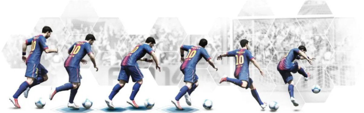
Figure 1.7. The captured frames of a dexterous shooting action of a football player (Courtesy of http://axeetech.com/) ... 19
Figure 2.1. Loop integrating designers into the motion planning process ... 26
Figure 2.2. Comparison of retraction processes in different methods ... 31
Figure 2.3. The cases related to the three rules considered in our retraction design ... 32
Figure 2.4. Penetration estimation in 2D and 3D ... 35
Figure 2.5. The construction process of spheres array ... 36
Figure 2.6. Sphere array in different resolution ... 36
Figure 2.7. Two cases with invalid penetration ... 37
Figure 2.8. The situations of convergence in two different cases ... 38
Figure 2.9. The comparison between a ‘good’ situation and a ‘bad’ situation ... 39
Figure 2.10. Experiment results of random retraction algorithm in the first case ... 41
Figure 2.11. Experiment results of random retraction algorithm in the second case ... 42
Figure 2.12. Penetration volume in different resolution ... 43
Figure 2.13. Valid and invalid retraction cases ... 44
Figure 2.14. The comparison of retraction time and number of retraction steps in different resolution and step length ... 46
Figure 2.15. Interactive motion planning system ... 47
Figure 2.16. Interactive planning in successful case and failed case ... 48
Figure 2.17. Connection of seeds by RRT-connect algorithm ... 50
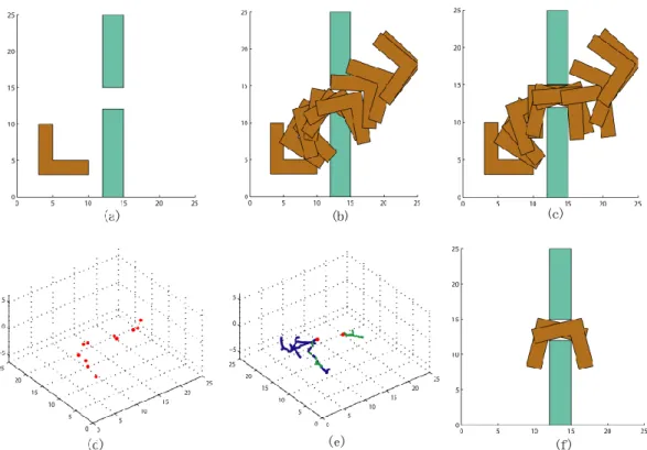
Figure 2.18. Successful case for an L shape part passing through a narrow passage ... 51
Figure 2.19. Exploration trace of basic BiRRT ... 51
Figure 2.20. Comparison between basic BiRRT and our interactive process ... 52
Figure 2.21. Failed case for an L shape part passing through a narrow passage... 54
Figure 2.23. The Planning process by our method in different sampling rates ... 56
Figure 3.1. Motion segment learned in a successful planning task ... 61
Figure 3.2. Learned motion segment is applied to the four similar scenarios ... 61
Figure 3.3. Similar scenario segments and their topological representations ... 63
Figure 3.4. Overview of the motion learning process ... 64
Figure 3.5. Sphere generation according to the position of the reference point ... 66
Figure 3.6. Sphere generation in a planar cluttered environment in two cases ... 67
Figure 3.7. Segmentation of scenario ... 69
Figure 3.8. Calculation of scenario skeleton’s curvature ... 71
Figure 3.9. Alignment between two similar skeleton segments based on curvature. ... 72
Figure 3.10. Imposing global constraint to limit the warping path ... 75
Figure 3.11. Sorted matching results for 4 query scenario skeleton segments by DTW using curvature feature ... 76
Figure 3.12. The Upper and Lower constraints on the curvature curve of a scenario skeleton ... 79
Figure 3.13. Piecewise aggregate approximation (PAA) of bounding constraints and the distance calculation between a query scenario segment and a minimum bounding rectangle. ... 80
Figure 3.14. An example of R-tree (Guttman 1984) ... 81
Figure 3.15. Bad and good split of an R-tree (Guttman 1984) ... 82
Figure 3.16. Process clustering scenario skeleton and its motion into motion library ... 83
Figure 3.17. Good and bad split of an R-tree in motion library ... 85
Figure 3.18. An R-tree constructed from ten scenario segments ... 86
Figure 3.19. Searching time in motion library with the R-tree structure ... 87
Figure 4.1. Overview of motion generation process ... 90
Figure 4.2. Motion Generation Process ... 91
Figure 4.3. Two invalid situations during the generation of the controlled point’s trajectory ... 93
Figure 4.4. Modified PRM is used to generate the trace of the controlled point ... 93
Figure 4.5. The computation of the length of roadmap edge ... 94
Figure 4.6. Scenario retrieval process ... 95
Figure 4.7. The ten retrieved scenario segments with similar skeleton to the query scenario segment (ID is the identifier number in the motion library; C is the dissimilarity distance of the curvature of scenario skeleton) ... 96
Figure 4.8. The five scenario segments selected from the ten retrieved segments (ID is the identifier number in the motion library; R is the dissimilarity distance of the radius of scenario)... 96
vii List of Figures
Figure 4.9. Motion transformation according to the skeleton transformation ... 97
Figure 4.10. Two feasible scenario segments selected in an interaction ... 99
Figure 4.11. The motion generation for the first selected scenario segment and its comparison to RRT-connect ... 101
Figure 4.12. The motion generation for the second selected scenario segment and its comparison to RRT-connect ... 102
Figure 4.13. Comparison between our method and RRT-connect in a complete planning process103 Figure 4.14. A non-feasible scenario segment selected during the interaction ... 104
Figure 4.15. Feasibility detecting for the third selected scenario segment and its comparison to RRT-connect ... 105
Figure 4.16. Two articulated models (The first is freely moveable in the workspace; the second is nailed to one point in the workspace) ... 106
Figure 4.17. Examples of reusing motion segments of two articulated model ... 107
Figure 4.18. The comparison of the of three different scenarios with ... 108
Figure 4.19. The comparison of the of three different scenarios with ... 109
Figure 4.20. The model of a simple car... 110
Figure 4.21. The planning results of the path of Dubin’s car by RRT algorithm in three tightly constrained scenarios with different topological structures ... 112
Figure 4.22. The Accessibility verification of a forklift in an industrial case with the construction of the scenario ... 113
List of Tables
Table 1.1. The comparison between different interactive devices ... 17
Table 2.1. Comparison between different interactive motion planning algorithm... 29
Table 2.2. The spent time and the change of in the first retraction case ... 41
Table 2.3. The spent time and the change of in the second retraction case ... 42
Table 2.4. The spent time and rates of successful retraction in different resolution and step length45 Table 2.5. The number of retraction steps in different resolution and step length ... 45
Table 2.6. The spent time of penetration evaluation in different resolution ... 45
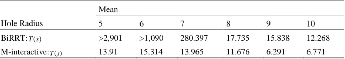
Table 2.7. Comparison between BiRRT and our interactive process in case of radius = 5 ... 52
Table 2.8. Comparison between BiRRT and our interactive process in case of different radius ... 52
Table 2.9. Planning result by RRT-connect ... 56
Table 2.10. Planning result by our method in the sampling rate 5 ... 57
Table 2.11. Planning result by our method in the sampling rate 10 ... 57
Table 2.12. Planning result by our method in the sampling rate 15 ... 57
Table 4.1. Comparison between our method and RRT-connect on the motion generation in the first example ... 101
Table 4.2. Comparison between our method and RRT-connect on the motion generation in the second example ... 102
Table 4.3. Comparison between our method and RRT-connect in a complete planning process 103 Table 4.4. Comparison between our method and RRT-connect on the motion generation in the third example ... 106
Contents
Acknowledgements ... i
Abstract ... i
Résumé ... iii
List of Figures ... v
List of Tables ... ix
Contents ... xi
Introduction ... 1
1 Problem Introduction and Literature Review... 5
1.1. Accessibility verification in the product design ... 5
1.1.1. Problem formulation ... 8
1.1.2. Configuration space ... 9
1.2. Accessibility verification by automatic algorithm ... 11
1.2.1. Sampling based motion planners ... 11
1.2.2. Narrow passage problem ... 12
1.2.3. Complete planning ... 13
1.2.3. Ergonomics analysis ... 13
1.3. Accessibility verification by manual manipulation ... 14
1.3.1. Manual manipulation in virtual environment with interactive devices ... 14
1.3.2. Constraints for humans ... 17
1.4. Introduction to the motion learning ... 18
1.4.1. Learning in the configuration space ... 20
1.4.2. Learning in the workspace ... 22
2 Interactive Motion Planning ... 25
2.1. Introduction ... 25
2.2. Previous work in the interactive motion planning (IMP) ... 27
2.3. Retraction based on the penetration depth ... 29
2.3.1. Retraction based motion planner ... 30
2.3.2. Random retraction method ... 32
2.3.3. Estimation of the penetration ... 34
2.3.5. Retraction results in applications ... 39
2.3.6. Conclusion... 46
2.4. IMP based on the retraction and the local connection ... 46
2.4.1. System global view ... 47
2.4.2. Seeds connection by the RRT-connect algorithm ... 49
2.4.3. Application cases ... 50
2.5. Conclusion ... 57
3 Motion Learning Based on Scenario Matching ... 59
3.1. Introduction ... 59
3.2. The hypothesis from an observation ... 60
3.3. Overview of the motion learning process ... 64
3.4. Scenario description and scenario skeleton generation ... 65
3.4.1. Medial axis ... 65
3.4.2. Curve skeleton ... 66
3.4.3. Scenario skeleton generation ... 66
3.4.4. Scenario segmentation ... 68
3.5. Similarity measurement of scenarios by DTW ... 69
3.5.1. Feature selection on scenario skeleton ... 70
3.5.2. Similarity measurement of scenarios by Dynamic Time Warping (DTW) ... 71
3.5.3. Conclusion... 77
3.6. Organization of scenario segments in motion library ... 77
3.6.1. Indexing structure of scenario segments ... 78
3.6.2. R-tree introduction ... 80
3.6.3. Clustering scenario segments with R-tree ... 82
3.7. Conclusion ... 87
4 Interactive Motion Planning with Learned Experience ... 89
4.1. Introduction ... 89
4.2. Motion generation process ... 90
4.2.1. Scenario selection ... 91
4.2.2. Motion retrieval ... 95
4.2.3. Motion transformation ... 97
4.2.4. Motion repair ... 98
4.3. Application results ... 98
4.3.1. Results in feasible scenarios ... 99
xiii Contents
4.4. Extension ... 106
4.4.1. Extension to the motion planning of articulated object ... 106
4.4.2. Extension to the differential motion planning ... 110
4.5. Conclusion ... 114
5 General Conclusions and perspectives ... 117
Bibliography ... 119
Introduction
The accessibility verification plays an important role in the process of product design, which usually dominates the cost and time of the design circle. The accessibility can be verified by the automatic algorithms or the manual manipulations equipped with the interactive devices. Defining the accessibility verification as the motion planning problem, the sampling based algorithms gained success on solving this kind of problem in the past fifteen years. However, all of them have some level of difficulty if the object’s free space has narrow passages which are regularly seen in some complex virtual assembly/disassembly tasks. Moreover, considering the evaluation of the constraints to the articulate system of human skeleton, and the preferences of users, the automatic algorithms always suffer from the redundant degrees of freedom and the difficulty of modeling uses’ preferences. The accessibility verification also promotes challenges to the manual manipulation of humans. Although humans possess advantages in the ability of global motion planning, they can lose their power in the local precise operations. Thus the manual manipulation is time-consuming for some tasks in which there is small tolerance between the manipulated object and the obstacles, or poor visibility. Besides, haptic feedback plays an important role in complex virtual manipulations. However, the haptic devices introduce limitations to the interaction as well, such as high cost, low degrees of freedom, and cumbersome mechanical structure, which usually prevent the integration with natural non-haptic devices in some tasks. All of these problems promote the interaction between users and automatic path planners in the accessibility verification process.
Summary of contributions
In this thesis, the objective is to improve the accessibility verification process for the product design. In considering the limitations in the automatic motion planning algorithms and human’s manipulation abilities, our research concentrates on integrating the algorithms and humans together, for the purposes such as accelerating the verification, reducing the difficulty of virtual manipulation and finding the motion path complying with the users’ preferences. Specially, the contributions include:
A novel random retraction algorithm is proposed to retract the penetrated configuration created by user to the configuration without penetration. Based on the retraction algorithm, a novel retraction based interactive motion planning method is proposed. Although the concept of some components in this method have been proposed by some previous studies, the integration of them with our random retraction method is new.
A new finding about the correlation between the topological information of scenarios and the motion path is studied. Then this correlation has been explored to establish a motion learning paradigm.
Scenario representation method is proposed, with which the similarity of scenarios is measured by the curve matching method.
The efficient motion segments clustering and retrieval methods are established with the R-tree structure.
The retraction based interactive motion planning method and motion learning method have been integrated as a new superior interactive motion planning framework which can learn from experience and release user from burdensome manipulations.
Organization of the thesis
Figure 1. Our interactive motion planning framework and the chapter structure
A global view to our interactive motion planning framework is demonstrated in Fig. 1. Without considering motion learning, the motion is planned from scratch by the retraction based interactive motion planning module which is discussed in the second chapter. Then the learning from experience and the management of motion experience are talked about in the third chapter. Finally, how to use the learned motion experience to serve the verification of accessibility in an interaction loop is shown in the fourth chapter. The fifth chapter is dedicated to the conclusion.
Chapter 1: Problem Introduction and Literature Review will firstly enumerate different kinds of accessibility verification problem in the product lifecycle. Then the mathematical description to the accessibility verification problem is demonstrated to promote the further discussion about its two available means of solution: the automatic algorithm and the manual
3 Introduction
manipulation. The bottlenecks for the two means of solution are analyzed respectively. Beyond these, a novel perspective about integrating the motion learning to solve the accessibility verification is proposed. And the detailed comparison of the related motion learning methods is given.
Chapter 2: Interactive Motion Planning will present and analyze the previous work which involves integrating the automatic motion planning algorithms with human manipulations. The retraction methods as an effective assistance to the sampling based planners will be explored and a novel random retraction method will be proposed. Then the convergence of the novel retraction method will be analyzed. Some limitations to the manipulation which guarantees the robustness of the retraction process will be talked about. Then a novel interactive motion planning method will be proposed in this chapter, which integrates humans’ manipulation, the random retraction method and the sampling based algorithm. Due to the addition of the retraction method, the user’s manipulation in the difficult region can be somewhat released from the burdensome operations by allowing some limited penetrations between the object and the obstacles. The final experimental results will show that the novel interactive motion planning method can efficiently reduce the time of accessibility verification in some difficult tasks.
Chapter 3: Motion Learning Based on Scenario Matching will firstly introduce a hypothesis about the correlation between the motion path and the topological structure and the volume size of scenario. Since the topological representation of a scenario is a 1D curve, the similarity measurement of scenarios is converted to the curve matching problem. The scenario in this thesis is represented by the maximal sphere sequence which can be efficiently generated. The centerline and the radius change of the sphere sequence provide two features for the comparison of scenarios. Based on the two features, the similarity of scenario can be measured by the Dynamic Time Warping (DTW) method. For the reason of efficiency and robustness of scenario comparison, the scenario is split by the proposed segmentation method. The motion segments with their scenario segments will be gathered into the motion library according to their similarity. In the motion library, the proposed method will organize the motion segments with the R-tree structure. Due to the hierarchical and balanced structure of the R-tree, the real-time searching in a motion library with millions of motion segments is possible. Since some modules of the proposed motion learning framework contains many wide research fields, the focus in this chapter is on the proposition of the novel framework.
Chapter 4: Interactive Motion Planning with the Learned Experience will present how to use the learned experience in the process of an interactive accessibility verification process. Based on the learned experience, the user’s mission of manipulation can be converted to selecting the scenario. A modified PRM (Probabilistic Roadmaps) algorithm is used to guide
the exploration of users’ manipulation. During the manipulation, only one point in the workspace is controlled by the user, in which manner the user will be released from the rotational operations of non-convex objects. After the scenario selection, a complete process will be started to divide the scenarios, and to retrieve, transform and repair the learned motion segments to fit each new scenario segment. A novel method which can efficiently determine the inaccessibility of the scenario according to the learned experience will also be proposed in this chapter. The rest of this chapter will discuss the possible extension of our motion learning and generation method to the articulated and differential model.
Chapter 5: Conclusion and Perspective will briefly summarize all the methods and the contributions of this thesis, and provide a perspective for the future work.
1 Problem Introduction and
Literature Review
1.1. Accessibility verification in the product design ... 5
1.1.1. Problem formulation ... 8 1.1.2. Configuration space ... 9
1.2. Accessibility verification by automatic algorithm ... 11
1.2.1. Sampling based motion planners ... 11 1.2.2. Narrow passage problem ... 12 1.2.3. Complete planning ... 13 1.2.3. Ergonomics analysis ... 13
1.3. Accessibility verification by manual manipulation ... 14
1.3.1. Manual manipulation in virtual environment with interactive devices ... 14 1.3.2. Constraints for humans ... 17
1.4. Introduction to the motion learning ... 18
1.4.1. Learning in the configuration space ... 20 1.4.2. Learning in the workspace ... 22
1.1. Accessibility verification in the product design
Globalization coupled with product customization and short-time to market has spearheaded new levels of competition among manufacturers, thus the verification and validation of engineering designs are of primary importance as they directly influence production performance and ultimately define product functionality and customer perception (Maropoulos and Ceglarek 2010). The efficiency of design process usually degrades dramatically with the increasing frequency of failure in the verification phase. An important factor considered in the verification phase is the accessibility.
What is Accessibility? Consider a mechanical assembly consisting of interacting parts. Is a given part can access a cluttered place without moving the other ones (Laumond 2006) ? The problem of accessibility is general among the whole product lifecycle. See Fig. 1.1 for a global view.
Figure 1.1. Accessibility verification in the product lifecycle
During the conceptual and preliminary design stages, the simulation of assembly and disassembly attempts to move a particular part without collisions between a free location outside the assembly and a predesigned assembly location. The predesigned assembly location of a component is the state at which it will be in contact with its mating component, namely the start of composing operation where these two components are going to be brought together by the selected joining method (Hsu and Lin 2002). The move involves computing the collision-free path for the rigid object with six degrees of freedom (DOF) among stationary obstacles (Garber and Lin 2002, Ferré, Laumond et al. 2005, Zhang, Huang et al. 2008). Since the significant design changes are often very costly, hence the verification of accessibility can help designers know what the minimal structural changes are to make sure objects do not collide with each other (Shellshear, Tafuri et al. 2014).
7
1.1. Accessibility verification in the product design
The accessibility verification problems also arise in the layout design. In the layout design, the accessibility deals with the required vacant space locating around the component, and is used to guarantee the correct mechanism of the component. Moreover, the accessibility requirement means that each component has to be attainable from the container’s entry (Bénabès, Bennis et al. 2010, Bénabès 2011). Recall the famous “piano movers’ problem” as an example (Schwartz and Sharir 1983), the design of the locations of furniture and the entry of room can determine whether the piano can access the destination.
For the industrialization and manufacturing, the accessibility verification helps designers detect the colliding or invalid kinematic errors of implementing the tools and robots in an early conceptual design phase. (Michalos, Makris et al. 2010) investigated the accessibility constraints introduced by the use of robots in a cooperative assembly simulation. (Hermansson, Bohlin et al. 2013) focused on the accessibility of deformable parts in the virtual manufacturing, such as the collision-free mounting of connectors in a wire hardness installation in an already densely packed vehicle. Moreover, the accessibility analysis is necessary to determine how to orient the CMM (coordinate measuring machine) probe to approach certain features or points, and which probe may be used to access a certain point without collision (Spyridi and Requicha 1991, Spyridi 1994, Spitz, Spyridi et al. 1999, Spitz and Requicha 2000). In (Jang, Moradi et al. 2008), the accessibility analysis is used to determine the set of all collision-free paths of the gripper from the access posses to the grasp poses in a cluttered environment.
In service and disposal stage, the accessibility verification is always considered in the maintenance operation in industrial facilities. (Chang and Li 1995) firstly proposed using the automated motion planning method to verify the accessibility in the disassembly maintainability study. The problem also arises when workers are forced to adopt ergonomically stressful, unreachable or kinematic-broken postures in connecting, disassembling, filling, stalling or repairing activities. In these cases, while the collision-free trajectory for the component may be feasible, the operation cannot be performed because of the interference between the arm or body of a worker with the obstacles, the shortage of the sufficient space for the arm, or the shortage of the proper visibility of the work area (Rajan, Sivasubramanian et al. 1999, Geng, Zhou et al. 2013). (Park, Choi et al. 2011) dealt with the accessibility verification of a remote manipulator for a maintenance task in nuclear facilities. In the context of logistics, the accessibility verification address the problems about whether a given body (e.g., tools, parts, loads…) can be moved from a place to another one by using the given transportation machines (e.g., manipulator robots, gantries, mobile platforms…) (Siméon, Laumond et al. 2001). The challenge is to compute the collision-free motion in tight-fitting scenarios with the extremely cluttered environment and different combinations of nonholonomic, mechanical or kinematic constraints introduced on the transportation machines. For example, the (Lamiraux,
Laumond et al. 2005) dealt with the accessibility verification of the trailer-truck on the specialized road loaded with the very large size freight, in which the trailer trucks are subject to rolling-without-slipping and going-only-forward constraints. (Lamiraux, Bonnafous et al. 2003) extended the complexity with considering two trailers. (Fonte 2011, Vale, Fonte et al. 2014) addressed the accessibility problem for an autonomous rhombic vehicle that operated in the buildings of the International Thermonuclear Experimental Reactor (ITER), in which the rhombic vehicle was modeled with two pairs (one for spare purposes) of drivable and steerable wheels positioned on the front and rear of the vehicle and two swivel wheels on the sides.
Computing a collision-free motion path for a particular object between different states (e.g., positions, orientations, poses…) is essential for all of the accessibility verification problems. The accessibility verification can be also regarded as the subset of the motion planning problems, however, the optimizations for energy and time are not always considered here.
1.1.1. Problem formulation
The accessibility verification involves computing a path in the object’s state space without colliding with the obstacles. Usually the underlying objects (e.g., assembling part, worker’s body, repairing tool, furniture…), noted as , and obstacles are complex and may be represented using thousands of polygons, and the models are given as polygon soup models with no connectivity or topology information. The 2D and 3D Euclidean space in which the objects move is called the workspace, which is noted as , or . The region of the workspace which is occupied by the obstacles refers to the obstacle region noted as . The state space describes all possible states that an object can have. The state could, for example, refer to the position and orientation of an assembling part or the pose of a human body. The state space is also called the configuration space noted as , in which every state of the object is represented as a point in the configuration space. A configuration is free if the moving object placed at does not collide with the obstacles or with itself. The collision-free space is defined as the set of all free configurations in .
(1.1)
Accordingly, the set of all configurations in which the object is in-collision with the obstacles refer to the configuration space obstacle noted as , . For the
accessibility verification problem, the obstacles are usually stationary in the workspace. The problem also contains an initial configuration and goal configuration .
So the accessibility verification problem can be formulated as computing a continuous path: , such that and
9
1.1. Accessibility verification in the product design
or correctly reports that such a path does not exist. (LaValle 2006) indicated that finding a feasible solution for such kind of problem is challenging, which is PSPACE-hard.
1.1.2. Configuration space
Using the configuration space to describing the states of moving objects is proposed by (Lozano-Perez 1983), in which each coordinate of the configuration space represents a degree of freedom in the position or orientation of the object (Wenger and Chedmail 1991). In Fig. 1.2 (left), a triangulated object can only translate in 2D workspace. For this object, its configuration space is 2D Cartesian space in which each configuration is defined by the and coordinates of the reference point on the object, . The configuration space obstacle for this
kind of object can be easily computed by Minkowski sum (Latombe 1991), shown as the region with diagonal texture in the Fig. 1.2 (right).
Figure 1.2. Configuration space of a 2D translating object
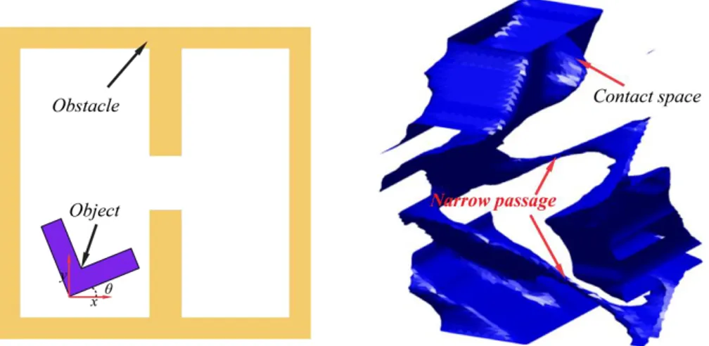
For a rigid object which is able to translate and rotate in 2D plane, its configuration space is the product of and , . Such an example is shown in Fig. 1.3, in which the configuration of the “L” shape object is represented as . The contact space of this object is computed through checking the collision situations of the uniformly
sampled configurations, and is shown in Fig. 1.3 (right). The contact space is defined as the set of configurations at which the object barely touches one or more obstacles without penetration, and it can also be regarded as the boundary of the configuration space obstacle .
Figure 1.3. Configuration space of an object freely moving in 2D plane
In 3D workspace, if a rigid object can translate and rotate, its action usually contains six degrees of freedom. As shown in Fig. 1.4, three coordinates in 3D Cartesian space represent the position of this object, and another three parameters are usually used to represents its orientation, where are the quantities of counterclockwise rotation angle about the axis, axis and -axis respectively. Thus, the configuration space of a free-flying rigid object is 6-dimensional and equals to the Cartesian product of two manifold subgroups: the group of translations and the group of rotations , .
Figure 1.4. Configuration of a free-flying rigid object in 3D
The precisely computation of collision-free space is very challenging. A general approach
for configuration space computation proceeds by enumerating contact surfaces for every pair of features from the object and the obstacle (Varadhan, Kim et al. 2006). Each contact surface is the locus of configurations of an object at which a specific boundary feature of the object (i.e. vertex, face, or edge of a rigid object represented as polyhedra) is in contact with a boundary feature of the
11
1.2. Accessibility verification by automatic algorithm
obstacles. The combinatorial complexity of the entire can be , where is the number
of contact surfaces and is the dimension of the configuration space (Zhang 2009). For a non-convex rigid object which is a polyhedron with polygons and is able to translate and rotate in a polygonal environment bounded by edges, the combinatorial complexity of is .
The recent breakthrough of computing in reasonable time the 6-dimensional configuration space of a rigid object is realized by (Nelaturi 2011, Nelaturi, Lysenko et al. 2012), in which the Fast Fourier Transformation (FFT) is used to efficiently compute the convolution of Minkowski sums with rotations.
1.2. Accessibility verification by automatic algorithm
On account of the complexity, the motion planning algorithms usually avoid the explicit construction of through sampling in the configuration space. During the late nineteen
nineties, sampling based strategies were proposed as a breakthrough to provide practical solutions to the motion planning problems.
1.2.1. Sampling based motion planners
The sampling based motion planners take samples in the object’s configuration space and connect these samples by a graph which captures the connectivity of the . This kind of algorithms
usually consists of three components: the sampling strategy, the local connection and the path query. These methods are said to be probabilistic complete, which means that the probability of finding a solution, if one exists, converges to 1 as the computing time tends to infinity (Jaramillo 2007). Depending on the strategy of constructing the graph, the sampling based motion planners are categorized into two families: Probabilistic Roadmaps (PRM) (Kavraki, Svestka et al. 1996) planners and Rapidly Exploring Random Trees (RRT) (Lavalle 1998) planners.
The main idea behind the PRM is to firstly take random samples in the object’s configuration space. Then the collision detection is implemented to test whether the sampled configuration is in the free space . If the sampled configuration lies in , it is connected by local planner to some
neighbors, typically either the k nearest neighbors or all neighbors less than some predetermined distance. Configurations and connections are added to the graph until the roadmap covers the connectedness of the space. In the query phase, the start and goal configurations are connected to the graph, and the path is obtained by a Dijkstra shortest path query. Since its creation, the details of basic PRM have been studied and extended by many variants, a comprehensive comparison between them can refer to (Geraerts and Overmars 2004). The PRM framework is suitable to solve
multiple-query problems, namely providing multiple initial configurations or goal configurations with the same object and obstacles.
In contrast, RRT planners are more appropriate for single-query problem. RRT is designed to efficiently search configuration space by randomly building an open-loop graph, or more precisely a space-filling tree. The tree is usually rooted at the initial configuration and is incrementally constructed by attempting the connection between the randomly sampled configuration and the nearest configuration in the tree. If the connection completely lies in , the sample and the
connection are added to the tree; otherwise, a valid part of the connection extended from the nearest configuration is added. An important property of RRT is that it is constructed by iteratively breaking large Voronoi regions into smaller ones, which results in the expansion is heavily biased toward unexplored portions of the configuration space (Lavalle, Kuffner et al. 2000).
The sampling based planners has been successfully used to solve many practical problems with high degrees of freedom (Latombe 1999). However, they all have some level of difficulty if the object’s free space has narrow passages (Denny and M. Amato 2013).
1.2.2. Narrow passage problem
Narrow passages are small regions whose removal changes the connectivity of the configuration space (Hsu, Kavraki et al. 1998, Sun, Hsu et al. 2005). The narrow passage problems usually arise when complex assemblies are composed of large number of parts, which often lead to scenes with high obstacle densities (Morato, Kaipa et al. 2013). The narrow passages occupy small volume in , thus any sampling distribution based on the volumes is likely to fail (Hsu, Jiang et al. 2003).
An example of narrow passages is shown in Fig. 1.3 (right), in which two narrow passages correspond to the “L” shape part passing the hole with clockwise and counterclockwise rotations. Any found path is essential to translate through one of the two passages. However, these two passages occupy so small volume which makes the search for a complete path extremely difficult. Different heuristics have been created to bias the sampling based planners to overcome narrow passage problem. Decomposition based planners decompose the configuration space into different kinds of cells and get an approximate corridor with A* algorithm, then explore in this corridor to find a collision-free path (Rosell, Vázquez et al. 2008, Ladeveze, Fourquet et al. 2009). Obstacle based planners either plan motion compliant to C-contact space with geometric formulations (Ji and Xiao 2001, Peng Tang and Jing Xiao 2008), or increase sampling around the obstacle (Amato, Bayazit et al. 1998, Boor, Overmars et al. 1999, Zheng, Hsu et al. 2005, Hsin-Yi, Thomas et al. 2012) and on the C-contact space (Redon and Lin 2005). In (Rodriguez, Xinyu et al. 2006), vectors generated on triangulated meshes of CAD model are used to guide the extension of basic RRT planner. Retraction based planners attempt to improve the sampling in narrow passages through
13
1.2. Accessibility verification by automatic algorithm
retracting in-collision configuration to the nearest configuration on C-contact space (Saha, Latombe et al. 2005, Liangjun and Manocha 2008) or the medial axis of free space (Wilmarth, Amato et al. 1999, Wilmarth, Amato et al. 1999, Lien, Thomas et al. 2003). Despite some improvements, narrow passages are still the major issue for sampling based planners. In fact, adding the consciousness of the local changes of workspace to algorithms will endure some expensive computation.
1.2.3. Complete planning
The complete planning issue arises when sampling based motion planners are applied to solve the accessibility verification problem. Compared to finding an exact motion, accessibility verification concerns more on the feasibility. An algorithm is considered complete if for any input it correctly reports whether there is a solution in a finite amount of time. However, such completeness is not achieved with sampling-based planning algorithms (LaValle 2006). If no collision-free path exists, sampling based algorithms may run for a long time before certificating that (Zhang, Kim et al. 2008). Due to the combinatorial complexity of the configuration space, some algorithms attempted to solve complete motion planning problem through the adaptive cell decomposition of the configuration space (Varadhan, Krishnan et al. 2005, Varadhan and Manocha 2005, Zhang, Kim et al. 2007, Zhang, Kim et al. 2008, Zhang, Kim et al. 2008). The subdivision of cells relies on efficient cell labeling algorithms which classify the cells into the empty cell (completely contained in ), the full cell (completely contained in ), and the mixed cell. Then a graph is
constructed by connecting the empty cells and mixed cells. The none-existence of a path on the graph provides a sufficient condition for path non-existence between the initial and goal configuration in . Although these methods contribute motivating solutions to the complete
motion planning, they cannot prevent unnecessary subdivision of cells and the complexity is increased of the non-convex object or degrees of freedom. As a result, the methods are limited to the rigid object with 3 or 4 DOFs.
1.2.3. Ergonomics analysis
For the accessibility verification, another challenge for designers is to test and verify the geometric constraints to the articulate system of human skeleton. A direct method is adding a digital human mannequin into the reasoning loop of motion planning algorithm. Combined with inverse kinematics, (Ferré, Laumond et al. 2005) successfully planned one hand manipulation with 7 DOFs and two hands manipulation with 15 DOFs of a virtual mannequin in less than one minute. However, in considering whole body delicate motion planning, up to 32 degrees of freedom will load a huge amount of calculation. Besides, the quality of generated motion of mannequin becomes a major issue, which mainly concerns reducing the redundant degrees of freedom and making the motion look more natural.
In addition, a key challenge for the designers is to analyze end-users’ response in the design process and promote product innovation, but users’ preferences are generally unable to precisely formulate (Poirson, Petiot et al. 2013). Thus, optimization for this issue with the automatic method is extremely difficult at present, and integration with the direct participation of designers is an essential stage (Bénabès, Poirson et al. 2013, Lu and Petiot 2014).
1.3. Accessibility verification by manual manipulation
The participation of designers in the accessibility verification process is in forms of manual manipulations of digital prototype in the virtual reality environment. Virtual Reality (VR) is a scientific and technical domain exploiting the possibilities of computers and behavioral interfaces to simulate in a virtual world the behavior of 3D entities, which interact in real time with each other and one or more users in pseudo-natural immersion through sensorimotor channels (Fillatreau, Fourquet et al. 2013). Virtual prototyping (VP) is the application of virtual reality for prototyping physical mock-ups (PMUs) using product and process data, of which the idea is to replace, at least partly, physical mock-ups (PMUs) by software prototypes (Gomes de Sá and Zachmann 1999). The virtual reality tools are intensively studied and applied to the design verification and validations in the product lifecycle (Jayaram, Jayaram et al. 2007, Maropoulos and Ceglarek 2010, Keller, Doceul et al. 2013).
Since the manual manipulation of digital prototype is usually realized by capturing humans’ motion with the interactive devices. The discussion of this section is related to the limitations of manual manipulations in the accessibility verification process, which arises with the limitations of the available interactive devices and the constraints of humans’ motion planning capabilities.
1.3.1. Manual manipulation in virtual environment with interactive devices
In accessibility verification tasks, the human motion is captured and transferred by the interactive devices to the control parameters which continuously change the position and orientation of the CAD model in the digital world. Depending on the task, the interactive devices are required to provide different number of degrees of freedom (DOF). If the task only involves the motion in 2D plain (e.g. pushing furniture, steering models of vehicles or aircrafts), two DOFs are required to represent the position of object and one additional DOF is needed for rotation. The 2D mouse and joystick which provide two or three simultaneous DOFs can fulfill most of these requirements. For manipulating rigid objects in 3D, at least six DOFs are required, in which three DOFs are used for the position and another three DOFs are used for the orientation. Based on whether force reaction
15
1.3. Accessibility verification by manual manipulation
signals can be send back to users, the interactive devices for controlling 3D object can be divided into two categories: the non-haptic device and the haptic device.
For non-haptic devices, the result of manipulation is usually only demonstrated visually. The commercial devices includes 3Dconnexion’s 3D mouse (
http://www.3dconnexion.com/
), ART’s Flystick (http://www.ar-tracking.com/
), Cyber Glove Systems’ data-glove (http://www.cyberglovesystems.com/
) and motion capture systems. The 3D mouse is non-portable which is only suitable for the desktop application, and the others are non-portable and extendible for applications in the larger workspace. The 3D mouse and Flystick can only capture movements of six DOFs, whereas data-glove and motion capture systems can capture more complex movements of hand’s fingers and human body’s joints. Based on whether the marker is used for capturing the motion, the motion capture systems can be divided into: the marker based system and the marker-less system.For the marker based motion capture system, the combinations of special markers are usually attached to the object to represent the position and orientation of the object. Some of the markers either reflect (ART
http://www.ar-tracking.com/
, Viconhttp://www.vicon.com/
, OptiTrackhttps://www.naturalpoint.com/optitrack/
and IoTrackerhttp://www.iotracker.com/
) or emit IR (infrared ray) signals to the measuring cameras. The others use pulsed DC magnetic sensors (Ascension Technologyhttp://www.ascension-tech.com/
) or the group of gyroscopes and accelerometers (Xsenshttp://www.xsens.com/
) as markers. The marker based motion capture system can offer good measurement accuracy and update rate, but it has drawbacks including: (i) it is time-consuming to put markers onto the tracked object; (ii) the attached markers may interfere with the object’s normal movement; (iii) and the high acquisition cost (Leu, ElMaraghy et al. 2013). The marker-less motion capture system either use stereo RGB camera, silhouette technique, the structured light technique or depth sensor to capture, estimate and recognize the pose of human body (Organic Motionhttp://www.organicmotion.com/
, Kinecthttp://www.microsoft.com/
, Intel®RealSensehttp://www.intel.com/
, and SoftKinetichttp://www.softkinetic.com/
). Compared to the marker based system, the marker-less based system has lower cost and more natural interface, but has lower accuracy and robustness.The non-haptic devices provide natural interface and can capture very complex movements of human body, which makes them suitable for some ergonomics studies in the loosely constrained environment. However, for the accessibility verification task, the movements of the non-convex object are always carried out in the cluttered scenes, which makes the simulation poorly visible or the virtual object partly or totally occluded. (Leu, ElMaraghy et al. 2013) indicated that the haptic feedback becomes essential for these situations. Some research has also concluded that the addition
of force feedback to the virtual environment allowed the participants to complete the task faster (Popescu, Burdea et al. 1999, Volkov and Vance 2001, Seth, Vance et al. 2011, Vélaz, Lozano-Rodero et al. 2013).
Haptic devices are the advanced technology that redoubles the simulation effects, which approximates real-world sensations in virtual, tele-operable, and hazardous environments (Park, Choi et al. 2011). Haptic feedback can be categorized into force feedback and tactile feedback. Force feedback relates to a virtual object’s hardness, weight and inertia, while tactile feedback simulates the user’s feel of the virtual object’s surface geometry, smoothness, slippage, temperature (Burdea 1999). Force cues provided by the haptic technology are created when an object crushes or penetrates into the obstacles, and can help designers feel and better understand the virtual objects by supplementing visual and auditory cues and creating an improved sense of presence in the virtual environment (Seth, Vance et al. 2011). The professional desktop haptic devices usually include Sensable Technologies’ PHANTOM from Geomagic (
http://geomagic.com/
), Haption’s Virtuose (http://www.haption.com/
), and Novint’s Falcon (http://www.novint.com/
). These devices can provide not only force feedback in three translational degrees of freedom but also torque feedback in three rotational degrees of freedom. But, these devices also have some drawbacks like: (i) the workspace limitations result in the restricted user motion in the environment; (ii) these devices need to be stably mounted, thus the user is constantly attached to a handle, their use with the bimanual manipulation and the associated whole body movement in immersive virtual environment becomes unfeasible (Seth, Vance et al. 2011, Vélaz, Lozano-Rodero et al. 2013).Figure 1.5. Some models of haptic devices
The wearable haptic devices such as CyberTouch, CyberGrasp (
http://www.cyberglovesystems.com/
) or Rutgers Master II (Bouzit, Burdea et al. 2002) can exert grasp forces that are roughly perpendicular to the fingertips. With these devices, users are able to feel the size and shape of the CAD models. Since only the fingers are constrained in collision and whole hand is freely movable, these devices cannot prevent the grasped object from penetrating or crushing other virtual objects, and thus are suitable for tasks that only involve dexterous manipulations. CyberForce (http://www.cyberglovesystems.com/
) can be regarded as the17
1.3. Accessibility verification by manual manipulation
combination of CyberGrasp and desktop haptic device. It provides a very natural haptic interface for hand manipulations, with which the users are able to sense the object’s shape and size as well as its mass and inertia. Because all haptic feedback devices incur significant costs and have strict geometry, placement and workspace requirements, these prevent them from being used widely (Leu, ElMaraghy et al. 2013). The comprehensive comparison of interactive devices can refer to Tab. 1.1. In the table, the “Simultaneous DOFs” refers to the number of degrees of freedom that the device can provide in once operation. The “Portable” refers to that the device is not stably mounted or connected by a cable with very limited action range. As we can see, no device can fulfill all the requirements. The choice of interactive devices depends on the specific manipulation task.
Table 1.1. The comparison between different interactive devices
Device Total DOFs Simultaneous DOFs Accuracy Tactile feedback Force feedback Portable Price
2D mouse 3 2 High N N N Low
Joystick 4 3 High N N/Y N Low
Flystick 6 6 High N N Y Low
3D mouse 6 6 High N N N Low
Motion capture system
Passive marker >6 >6 High N N Y High Active marker >6 >6 Medium N N Y High Marker-less >6 >6 Low N N Y Low Electromagnetic >6 >6 High N N Y High Inertial >6 >6 High N N Y High Desktop haptic device 3~6 3~6 High N Y N Medium Data glove >6 >6 High N N Y High CyberTouch, CyberGrasp,
Rutgers Master II
>6 >6 High Y N Y High
CyberForce >6 >6 High Y Y N High
1.3.2. Constraints for humans
Although the virtual reality technique and interactive device provide the possibilities to evaluate issues related to the ergonomics, the manual manipulation is time-consuming for some tasks with small tolerance between the manipulated object and the obstacles, or poor visibility. For example, (Ferré, Laumond et al. 2005) has shown that, for the task of disassembling a wiper motor from the car body (Fig. 1.6 (a)), the automatic algorithm found the solution within one minute whereas a manual search took around 2 to 5 days of an experimented operator. Since the manipulated object is highly non-convex in this kind of tasks and the scene is only partially visible to the humans, it is difficult for humans to solve the problem even in real life. Another similar example is the famous “hedgehog puzzle” which is shown in Fig. 1.6 (a) right. The puzzle consists of a small sphere with
protruding spikes of various lengths contained within a cylinder perforated with holes of different sizes. The challenge posed by the puzzle is how to release the sphere (the hedgehog) from the cylinder (the cage). This puzzle usually spends several hours or days to solve for the players without any prior knowledge.
However, humans have some advantages in planning the motion globally. It is easier for humans to know “where to go” than “how to go”, whereas the situation is opposite for the automatic algorithms. For example in Fig. 1.6 (b) left, the mission involves inserting a stick into a bug-trap. The solution to this mission is obvious to humans but difficult to the automatic algorithm. If the bug-trap is designed more complex like in Fig. 1.6 (b) right, the difficulty of finding the path between initial and goal configurations has not much increase for humans, but it is extremely difficult for automatic algorithms. The available solutions, which attempt to enhance both humans and automatic algorithms in a motion planning task, allow the user and the algorithm work in a complementary fashion. This topic will be deeply discussed in the second chapter. In the next section, we raise another discussion which can lead to an efficient solution to the accessibility verification in a new perspective.
Figure 1.6. Advantage and disadvantage of human’s capability of motion planning
1.4. Introduction to the motion learning
Although humans do not possess the capabilities of accurately computing the complex movements in some difficult situations, they show some talents to make very complex movements in reaction to the change of the environment, and this reaction is usually made in a very short time. For example, Fig. 1.7 shows the captured frames of a dexterous shooting action of a famous football player. The action from the video game is produced by firstly recording the movements of a real football player with the motion capture system introduced in the Section 1.3.1. The movement is so complex that it involves the appropriate running velocity, good body’s balance keeping, perfect cooperation of four limbs and accurate choice of the contact point between the foot and the ball. More than thirty