THÈSE
En vue de l'obtention du
DOCTORAT DE L’UNIVERSITÉ DE TOULOUSE
Délivré par :l’Université Toulouse III – Paul Sabatier Discipline ou spécialité : Génie Electrique JURY Pr. Georges ZISSIS Dr. David BUSO Pr. Muqing LIU Pr. Belkacem ZEGHMATI Pr. Corinne ALONSO Dr. Zéphirin MOULOUNGUI Dr. Christophe MARTINSONS Mr. Thomas PRUDHOMME Dr. Laurent CANALE Directeur de thèse Codirecteur de thèse Rapporteur Rapporteur Examinateur Examinateur Examinateur Examinateur Invité
Ecole doctorale : Génie Electrique, Electronique et Télécommunications (GEET) Unité de recherche : LAboratoire PLAsma et Conversion d'Energie (LAPLACE) UMR 5213 Directeur de Thèse : Georges ZISSIS et David BUSO
Rapporteurs : Muqing LIU et Belkacem ZEGHMATI Présentée et soutenue par :
Feng TIAN Le 06/12/2016
Titre : Etude et optimisation des systèmes d'éclairage pour la croissance des plantes en milieu contrôlé
Title : Study and optimization of lighting systems for plant growth in a controlled environment
Acknowledgements
As the time flying away, the years shuttling again, three years have passed in a split second, and I will complete my Ph.D. life in lovely Toulouse, France. At the moment, I would like to express my sincere gratitude to Professor Georges ZISSIS, my research supervisor, the director of ‘Light and Material’ group in Laplace. He has deep insight and understanding on lighting science and technology with focus on the latest light sources, light technology application and light degradation mechanism, and he has done a great work on this domain. Not only the great academic influences, his personality charm: energetic and approachable is being admired greatly. Thank him for his words and demonstrations leading me to the Scientific Palace. I acquired a lot during the three years, which would affect my whole life.
I would like to express my grateful thanks to Dr. Laurent CANALE and Dr. David BUSO. With a cheerful, humorous, hospitable and talkative characters, Laurent give me a colorful time in Toulouse. He is an experienced engineer; not only in my experiments and study, he gave me a favorable guidance, but also helped me much in my daily life. He is my teacher as well as my friend. David works earnestly andresponsibly. We did the same project together. He had a keen insight on the research and gave me a lot of helpful suggestions. Without his assistance and guidance, I cannot complete my work very well. I hope the next cooperation with him.
I would like to thank the jury: Pr. Muqing LIU (reviewer), Pr. Belkacem ZEGHMATI (reviewer), Pr. Corinne ALONSO (examiner), Dr. Zéphirin MOULOUNGUI (examiner),Dr. Christophe MARTINSONS (examiner) and Mr. Thomas PRUDHOMME (examiner).
I would like to say thanks to all the teachers and technicians in our group, such as Mr. Pascal DUPUIS, Mr. Manuel LOPES, Mr. Marc TERNISIEN, Mr. Cédric RENAUD, Mr. Jean-Luc, Mr. Gérald LEDRU, etc. It is my great honor to work with them. They are all my role models to learn how to do the scientific research.
I thank my dear colleagues: Angel BARROSO, Benoit BLONDEL, Benjamin RAMOS, Sovannarith LENG, Alaa ALCHADDOUD, Urbain NIANGORAN, Yuan ZHANG, Xiaolin HUANG, Bo QIAO, Lumei WEI, Chenjiang YU, Song XIAO, Dongxi HE, Fang LEI, Linlin ZHONG, Fei WANG, Xi LIN, Li WU, Tianyi LIU, Wencong ZHANG, Jingyi WANG, etc. It is indeed my pleasure to exchange experiences and cooperate with them. Thus, I could improve my work quality and efficiency, and complete my thesis in time.
I appreciate the assistance and advice from the engineers of LAPLACE, such as Jacques SALON, Stéphane MARTIN, Nordine OUAHHABI, Vincent BLEY,Cédric TRUPIN, Céline COMBETTES, etc. Without your kindly help, I cannot complete the experimental design and measurements.
I appreciate Biosentec company for the financial and biotechnical support, so we can complete the biological experiments and project.
I thank the teachers and classmates in INRA for the help of biological science and technology, such as Dr. Hua WANG, Dr. Zhongtao ZENG, Yanwei HAO, Hong YU, Qiang LI, Liyan SU, Binbin ZHOU, Gaofei JIANG, Xiaoyang ZHU, Guojian HU, Baowen HUANG, Tongming WANG, Yi CHEN, etc.
I must thank University Paul Sabatier (UPS) of Toulouse, National Center for Scientific Research (CNRS), Laboratory on Plasma and Conversion of Energy (LAPLACE), Light and Material (LM) group, which provide an excellent and comfortable academic environment and friendly atmosphere.
I thank professor Weibin CHENG, who was my supervisor during my master period. He broadened my horizons and guided me to the bright prospect of my life.
I would like to say thanks to all the members in Laplace and all my dear friends in France and China for their encouragement and support.
Table of Contents
Acknowledgements ... I
Table of Contents ... 3
Abbreviations and Symbols ... 7
General Introduction ... 9
Chapter 1 State of the Art ... 15
Synopsis ... 17
1.1 Research background ... 18
1.1.1 Population explosion ... 18
1.1.2 Food supply and security ... 18
Insufficient food supply ... 18
Food safety problems ... 19
1.1.3 Agricultural economy problems ... 20
1.1.4 Environmental pollution and climate change ... 20
1.1.5 World energy crisis ... 21
1.2 Traditional farming vs controlled environment agriculture ... 22
1.2.1 Controlled environment agriculture ... 22
Definition of controlled environment agriculture ... 22
Reasons to develop CEA ... 23
Characteristics of CEA ... 23
1.2.2 Commercial greenhouse ... 24
1.2.3 Industrial plant factory ... 25
1.2.4 Significances of CEA ... 28
1.3 Light sources & lighting systems for CEA ... 28
1.3.1 Light sources ... 28
Legacy light sources ... 28
1.3.1.1.a Incandescent lamp ... 28
1.3.1.1.b Fluorescent lamp ... 30
1.3.1.1.c High intensity discharge lamp ... 31
Solid state light sources ... 33
1.3.1.2.a Light Emitting Diode ... 33
Comparison of different light sources ... 35
1.3.2 Artificial light and plants ... 37
Legacy light in CEA ... 38
LED light in CEA ... 38
Light Environment for plant growth ... 41
1.3.2.3.a Introduction ... 41
1.3.2.3.b LED based photobiology ... 42
1.3.2.3.c Spectra for plant growth ... 43
1.4 Plant selected in this study ... 43
1.5 Conclusion ... 44
Chapter 2 LED Characteristics: Experimental Setup & Measurements ... 45
Synopsis ... 47
2.1 Experimental setup ... 48
2.1.1 Junction temperature measurement based on temperature control box ... 48
2.1.2 Light measurement system for LEDs properties ... 48
2.2 Measurement for LED characteristics ... 50
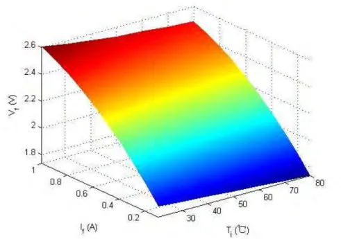
2.2.1 Electrical characteristics ... 50
2.2.2 Thermal characteristics ... 51
2.2.3 Spectral characteristics ... 52
2.2.4 Colorimetric characteristics ... 55
2.3 Modeling LED behaviors ... 57
2.3.1 Electrical model ... 57
2.3.2 PAR model ... 58
2.3.3 Spectral model ... 59
2.4 Conclusion ... 60
Chapter 3 Design of LED Lighting System for Plant Growth ... 61
Synopsis ... 63
3.1 Introduction ... 64
3.2 Design and analysis... 64
3.2.1 LED unit ... 65
3.2.2 Power module ... 66
3.2.3 Control module ... 67
3.2.4 Driving module ... 68
3.2.5 PC software ... 70
3.4 Conclusion ... 74
Chapter 4 LED Lighting system efficiency measurement and optimization 75
Synopsis ... 774.1 Introduction ... 78
4.1.1 Relative quantum efficiency ... 78
4.1.2 Photosynthetically active radiation ... 79
4.1.3 Light regime for plant growth ... 79
4.2 Experimental results ... 80
4.2.1 RQE curve fitting using additive color mixing with five colored channels. ... 80
4.2.2 Spectrum efficiency for plants ... 81
Light measurement systems for plants ... 82
4.2.2.1.a PPF ... 82
4.2.2.1.b EPPF ... 83
4.2.2.1.c YPF ... 83
4.2.2.1.d Phytometric system ... 84
Results and discussions ... 84
4.2.2.2.a Results of normalized spectrum ... 84
4.2.2.2.b Results of real spectrum at nominal current ... 85
4.3 Simulation of LED spectrum for average plants ... 86
4.3.1 Smoothness of RQE curve ... 86
4.3.2 Simulation with multi-term Gaussian model ... 87
4.3.3 RQE simulation with 12 LED spectra within PAR ... 90
4.4 Conclusion ... 92
Chapter 5 Application to Spirulina Platensis culture ... 93
Synopsis ... 95
5.1 Spirulina platensis ... 96
5.1.1 The value of S. platensis... 96
A nutritional food ... 96
Medicinal values ... 96
5.1.2 Cultivation of S. platensis under PARS ... 97
5.2 Light requirement for S. platensis ... 97
5.2.1 Major pigments in S. platensis ... 98
5.2.2 Photosynthesis irradiance (PI) curve ... 98
5.3 Absorbance of S. platensis ... 100
5.3.1 Beer’s law ... 100
Design of test container for absorbance ... 100
Test system for absorbance of S. platensis ... 102
Test results for absorbance ... 103
5.3.3 Dry biomass determination ... 104
5.4 Experimental materials and methods ... 106
5.5 Effect of LED spectrum on the growth of S. platensis ... 107
5.5.1 Influence of LED colors ... 107
5.5.2 Spectrum selection and optimization ... 108
5.5.3 Optimization LED efficiency and distribution ... 109
5.5.4 Optimization of light intensity ... 111
5.6 Effect of intermittent light ... 112
5.6.1 Intermittent light... 112
5.6.2 Experimental result under intermittent light ... 113
5.7 Effect of red and blue LEDs on the production of phycocyanin by Spirulina platensis 114 5.7.1 Introduction ... 114
5.7.2 Materials and Methods ... 115
Culture conditions for phycocyanin ... 115
Phycocyanin content detection ... 115
5.7.3 Results and discussion ... 116
Growth curve of S. platensis ... 116
Mass fraction of phycocyanin ... 117
5.8 Spirulina growth modeling ... 118
5.8.1 Modified Monod model for specific growth rate ... 118
5.8.2 PI model analysis for photosynthetic rate ... 120
5.8.3 Analysis of economic efficiency for the best harvest time ... 121
5.9 Conclusion ... 123
General Conclusion and Perspectives ... 125
Annexes ... 131
List of Figures ... 133
List of Tables ... 137
Abbreviations and Symbols
APC - allophyxoxyanin
ATP - Adenosine Triphosphate
CCFL - Cold Cathode Fluorescent Lamp CCT - Correlated Color Temperature CEA - Controlled Environment Agriculture CFL - Compact Fluorescent Lamp
CFU - Colony Forming Unit
COP21 - 21st Conference of Parties DFT - Deep Flow Technique
EL - Electroluminescent
EPPF - Equal Photosynthetic Photon Flux ETMs - Electrical Test Methods
FAO - Food and Agriculture Organization FWHM - Full Width at Half Maximum Gtoe - Gigatonne of Oil Equivalent HID - High Intensity Discharge HPS - High Pressure Sodium IOT - Internet of Things LCD - Liquid Crystal Display
LECS - Light Environment Control Strategy LED - Lighting Emitting Diode
LR - Lighting Recipe
MDG - Millennium Development Goal MH - Metal Halide
MIMO - Multiple Input and Multiple Output MISO - Multiple Input and Single Output MTTF - Mean Time to Failure
MUC - Microprogrammed Control Unit
NADPH - reduced form of Nicotinamide Adenine Dinucleotide Phosphate NFT - Nutrient Film Technique
OD - Optical Density
OTMs - Optimal Test Methods PAN - Pesticide Action Network
PAR - Photosynthetically Active Radiation PARS - Plant Artificial Radiation Sources PC - Phycocyanin
PE - phycoerythrin
PFAL- Plant Factory with Artificial Lighting PI - Photosynthesis Irradiance
POR - Power on Reset
PPF - Photosynthetic Photon Flux
PPFD - Photosynthetic Photon Flux Density PSoC - Programmable System-on-Chip PWM - Pulsed Width Modulation RQE - Relative Quantum Efficiency RTC - Real Time Communication SPD - Spectral Power Distribution WFS - World Food Summit
WSM - Wavelength Shift Method YPF - Yield Photon Flux
- duty cycle - light frequency
- Junction Temperature - Forward Current
- photosynthesis rate
- light-saturated maximum photosynthetic rate - light/dark cycle
- dark period - light period
- Forward Voltage
α - light-limited initial slope ε - light fraction
μ - specific growth rate
μ - maximum specific growth rate - luminous flux
Artificial lighting systems can be used for plant growth in controlled environment agriculture (CEA, also called protected horticulture). Their main function is to improve the quality and quantity of agricultural products. Plant factories and greenhouses with supplemental lighting are the concrete manifestations of CEA. Their development is based on the application of Plant Artificial Radiation Sources (PARS), which means that the sunlight has not been the unique light source for agricultural production but can be replaced by PARS. Especially, Plant Factory with Artificial Lighting (PFAL) is a modern agricultural innovative technology that fundamentally change the concept of farming. How to select the light source and optimize the lighting system for plant growth are of great importance.
However, there are some key issues for this new technique. First, some people do not understand well the characteristics of artificial light sources. Second, photobiology mechanism under different spectra is not clear enough for all the species. Third, agricultural field is a large system of great complexity. As a result, the PARS are improperly selected and usually have low efficiency and high energy consumption, which become the main obstacles for applications.
Lighting emitting diode (LED) is known as the latest light source. Compared with legacy light sources, it has unparalleled advantages such as high efficiency, long lifetime, flexible spectrum, monochromatic light, cool spectrum, small size, robust, etc. Besides, LED lighting systems use DC power supply, which are more reliable and easier to control. Therefore, LED lighting systems become more and more popular to the researchers, design engineers, manufacturers and biologists. Particularly, LED applications for agricultural production also attract broad attention in the world in recent years. LED is an ideal choice to spread in the protected horticulture.
In order to promote agricultural application of LED lighting system, there is urgent demand for understanding LEDs and matched lighting systems. Optimization of LED lighting systems for protected horticulture has great significance for modern agriculture. It is not a lighting system for human eye but a special facility for plant growth. Take the advantage of monochromatic spectrum of LED, and do research on the effect of specific spectrum on plants for the optimal light quality, quantity and photoperiod.
First of all, a lighting system was designed considering generic plants. This part took into account the Relative Quantum Efficiency (RQE) curve, which is actually based on the light response of 22 average photosynthesizing plants. In a second step, we focused on a particular species, spirulina platensis, that feature unique characteristics, like fast growing rate and relatively simple metabolism. The second part was supported by the program EPICURE funded by Region Midi-Pyrénées and European FEDER.
The dissertation is divided into the following five parts:
Chapter 1: Introduce the research background and situation of this topic. The key points are focused on the history, characteristics, applications and issues of artificial light sources; it clearly highlights the characteristics and advantages of LED light sources and their applications. The concrete manifestations of controlled environment agriculture, plant factories and greenhouses are introduced; PARS and PFAL are mainly discussed as the core environmental factor for plant growth. Besides, LED based PARS linked to hunger world problems is also introduced, which shows that optimization of LED lighting systems for plant growth has great significance to improve current situation.
Chapter 2: In this chapter, the experimental setup to measure LED characteristics, including electrical, optical, thermal and colorimetric characteristics is presented. The electrical, PAR and spectral models of some LEDs are analyzed. Results obtained was then used as a basis to design the LED lighting system for plant growth.
Chapter 3: According to the characteristics of LEDs, a specific LED lighting system is designed for greenhouse plants. We chose five LED colors: red, amber, green, blue and white within PAR to match the useful spectrum of plant growth. The design principle and process is described in detail. The system chart, schematic diagram and its basic functions are presented. Two operating modes of the system can be available, automatic and manual mode, which can flexibly change the forward current, frequency, duty cycle and period. The system can be programmed based on the characteristic of selective light absorption spectrum for certain plants. Power consumption is also reduced and finally, the system can dynamically adjust the light quality, quantity and photoperiod according the test conditions.
Chapter 4: The spectra of LED is optimized for average plants based on relative quantum efficiency curve. The light efficacy is defined for each channel of the LED lighting system. Different light measurement systems for plants are described including photosynthetic photon flux (PPF), yield photon flux (YPF) and equal photosynthetic photon flux (EPPF). A relatively new concept of light measurement in the field of horticulture is also described by phytometric system. The light efficacy for plant growth is demonstrated by the application of five kinds of light emitting diode within PAR of 400 to 700 nm. In order to theoretically find the best combination of LEDs, the RQE curve was simulated by Gaussian models according on the principle of additive color mixture. Results suggests that twelve different LEDs are required to accurately reproduce RQE in the range of photosynthetically active radiation (PAR).
Chapter 5: The spectra of LED is optimized for Spirulina platensis (S. platensis). S. platensis is selected as the target plant due to a much shorter life cycle as well as the nutritional and medicinal properties. The light requirement for S. platensis is analyzed
according to the major pigments and PI (photosynthesis irradiance) curve. The absorbance of S. platensis is measured by a special design of test container based on Beer’s law. In order to get the optimal spectrum for biomass production, we used various kinds of LEDs with different spectra, intensities, powers, light distributions and patterns to cultivate S. platensis. In order to know how light spectrum effect on the pigment of phycocyanin (PC) in S. platensis, five different ratios of blue and red light are adopted for the experiment. The improved Monod model and PI model were used to properly evaluate the specific growth rate and photosynthesis rate, which was favorable to understand light-limited, light-saturated, photo-inhibited and photo-acclimated regions. Besides, the economic efficiency is also discussed according two criterions: harvest time and concentration of S. platensis.
This thesis will end with the general conclusion and perspectives. In this part the interesting conclusions are summarized for each chapter, such as the most efficient light for plant growth and the best harvest time for S. platensis in different light conditions. At last, the future works are anticipated in this domain.
This work was developed in “Lumière et Matière” (LM) research group of Laboratoire Plasma et Conversion d’Energie (LAPLACE), University of Toulouse Ⅲ Paul Sabatier, Toulouse, France. The scholarship of Ph.D. for Feng TIAN is supported by China Scholarship Council (CSC).
Chapter 1
State of the Art
Synopsis
Artificial light sources and lighting systems are the core technology to develop controlled environment agriculture (CEA). In the background of world crises and social issues, CEA can effectively reduce agricultural risk and enhance quality and quantity of production. The key points in this part are focused on the history, characteristics, applications and issues of artificial light sources, clearly highlights the characteristics and advantages of LED light sources and its applications. As the concrete manifestations of protected horticulture, plant factory and greenhouse are introduced. Plant Artificial Radiation Sources (PARS) are mainly discussed as the core environmental factor for plant growth. Optimization of LED lighting systems has great significance to develop protected horticulture, which could be a good production mode to solve the social issues. At last, we chose Spirulina platensis as the experimental subject due to a much shorter growth cycle as well as its nutritional and medicinal properties.
1.1
Research background
1.1.1
Population explosion
The United Nations recently released population projections based on data until 2012 and a Bayesian probabilistic methodology. The data reveals that world population will increase from the current 7.2 billion to 9.6 billion in 2050 and 10.9 billion in 2100 (Figure 1-1 (a)). The projections of total population for each continent to the end of the century is shown in Figure 1-1 (b). Asia will probably remain the most populous continent, although its population is likely to peak around the middle of the century and then decline. The projected population of Africa is increasing very fast, which will be up to between 3.1 and 5.7 billion by the end of the century [1].
The larger the population there is, the greater demand for energy and food. The growing needs for daily necessity could not be met by the traditional agriculture technology. If the conventional ideas and production methods are not changed in time, it could lead to serious social problems.
(a) (b)
Figure 1-1 UN 2012 world population projection (solid red line), with 80% prediction interval (dark shaded area), 95% prediction interval (light shaded area), and the traditional UN high and low variants (dashed blue
lines) (a) and UN 2012 population projections by continent (b) [1].
1.1.2
Food supply and security
Insufficient food supply
If a person is not able to eat sufficient food to meet the basic nutritional needs, he or she is undernourished. In 2014-2016, the total number of undernourished people in the world is about 795 million (Figure 1-2), which means that over one in every nine people are currently unable to consume enough food to conduct an active and healthy life. The second indicator is the prevalence of underweight children under five years of age. In the developing regions the prevalence of undernourishment and child underweight is about 15% [2].
Paying attention to the insufficient food supply, United Nations members have made two important policies to confront world hunger: The World Food Summit (WFS) in 1996 and the First Millennium Development Goal (MDG) in 2000 with the target to reduce the hanger to half by 2015 [3, 4]. Many countries that have achieved considerable progress, but hunger is still an everyday challenge for 780 million people in the developing countries and 795
million worldwide. In a word, hunger eradication is a daunting task that more efforts should be done to overcome hunger and malnutrition.
Figure 1-2 The numbers and shares of hunger and undernourished people in the world [2] Food safety problems
Each year in the United States alone, it is estimated that 76 million Americans suffer from food-borne diseases, more than 33 million people are sent to hospital for food related illnesses, and about 5,000 people die. The cost in lost wages, insurance claims and medical bills amounts to between $7.7 and $23 billion a year [5-7]. Recently, food safety issues have gained national attention. The quality and safety of food for human consumption demand prompt solution.
The food safety problems are mainly as follows:
A. Foodborne Illness–Foodborne illness is still the most prevalent risk with food, largely caused by contaminated food and drinking water wherein diseases bacteria, viruses, prions and parasites. High-density and low-sanitation livestock facilities spread the diseases more rapidly [8].
B. Pesticide Exposure–Pesticides are used in many agricultural operations, but it has the potential to cause adverse human health. Human exposure to pesticides can occur through ingestion of contaminated foods, drinking water, and animal products due to bioaccumulation, inhalation, or skin contact. The Pesticide Action Network UK (PAN UK) (2013) reported that nearly two thirds (63%) of supermarket own-brand loaves and top brand-name loaves analyzed in 2013 contained traces of 1 or more pesticides [9].
C. Food Contaminants–There are many other substances such as heavy metals like lead, mercury, and cadmium are occasionally found in food, which can lead to serious cases of poisoning, as well as related health issues like Minamata disease from mercury and Itai-Itai disease from cadmium [10, 11].
D. Antibiotic Resistance–Emissions of antibiotic residues and resistant bacteria from various human activities, including animal production, fish production, wastewater treatment, and antibiotic manufacturing, will increase the burden of antibiotic resistance in exposed
environmental matrices. The abundance and the mobility of antibiotic resistance genes in agricultural soils may be enhanced by various management practices, for example, the application of animal manures, wastewater, or waste treatment residues that contain antibiotic resistance genes on mobile elements and antibiotic residues [12-14].
E. Environmental Effects–Soil, water and air are polluted by irrational exploitation and utilization through agricultural activities. The food quality is also badly influenced. Luckily, with the continuous improvement of awareness, ecological agriculture could be realized by innovative science and technology.
1.1.3
Agricultural economy problems
Currently, agriculture is often subsidized by national government. It seems to be one of the most difficult industries. Farmers often suffer from economic problems, especially in developing countries. However, it still plays an important role for employment and the farmers’ main source of income. Farmers focus on maximizing the crop yield by expanding the area of arable and using chemical fertilizers. The phenomenon has led to deforestation and greater environmental cost for little benefit. The quality of crop and soil become worse and worse. This can upset the eco-balance and cause pollution. The destruction of land resources, low productivity and large environmental impact frequently decline agricultural status and income, which lead to market failure.
The poor remain especially vulnerable, as the Food and Agriculture Organization (FAO) has warned repeatedly. The FAO’s world food-price index had risen to a record high in early 2011, topping the previous all-time high set in June 2008. As a result, rising food prices have driven an estimated 44 million people into poverty (World Bank, 2011) [15].
Therefore, new agricultural production mode should be adapted to improve the livelihoods and incomes of the poor. It aims to fight hunger and food insecurity, enhancing the productivity of resources, promoting economic integration, and for attaining sustainable progress.
1.1.4
Environmental pollution and climate change
Energy and environment is the foundation of mankind's development. Every citizen has the responsibility and obligation to conserve energy and protect environment.
However, in order to get more natural resources, irrational exploitation and utilization cause serious pollution and destruction of ecological environment, such as the emergence of the greenhouse effect, pollution (air, water and soil), global climate change, species extinction, ozone depletion, desertification, acid rain, deforestation, ocean acidification, transboundary pollution, loss of biodiversity, soil erosion, public health issues, etc. These terrible global environmental issues threaten to the survival and development of mankind. Carbon dioxide (CO ) is one of the main greenhouse gases to accelerate global warming. Oil, coal and gas are the principal sources for CO emission (Figure 1-3 (a)). The burning of fossil fuels produces around 21.3 gigatonnes of CO per year, but it is estimated that natural processes can only absorb about half of that amount, so there is a net increase of 10.65 billion tonnes of atmospheric carbon dioxide per year [16, 17]. Measurements of CO from the Mauna Loa observatory show that concentrations have increased from about 313 parts per million (ppm) in 1960 to about 406.81 ppm in 2016 [18]. Besides, the burning of fossil fuels also brought other air pollutants and toxic gases, such as nitrogen oxides, sulfur
dioxide, volatile organic compounds and heavy metals, which will destroy the ecological environment [19, 20].
Simulated global mean surface temperature shows the global temperature changes (Figure 1-3 (b)). In the end of 21th century the temperature will increase about 4.5℃ compared with the year 1861-1880. It is a great challenge for the survival of human beings.
So a global movement is under way to reduce CO emission. The pledges and determination demonstrated at the COP21 (21st Conference of Parties) meeting in Paris are likely to lead to further policies aimed at shifting the fuel mix towards cleaner, lower-carbon, fuels, with renewable power, along with natural gas, the main beneficiary [21].
(a) (b)
Figure 1-3 Global Greenhouse Gas Emissions by Gas (a) [22], Simulated global mean surface temperature increases as a function of cumulative total global 2 emissions (b) [23]
1.1.5
World energy crisis
Industrial development and population growth have led to a surge in the global demand for energy in the world in recent years. Until now, the world's energy crisis broke out several times from 1970s, which triggered a series of social problems in transportation, finance, business, politics, and even evolved into a war. The price of oil reached the highest of $147.30 per barrel in 2008, and resulted in high inflation with recession [24, 25].
Fossil fuels have been the main energy sources for 200 years, but they are non-renewable and limited resources. Oil, gas and coal remain the world’s dominant fuel, about 32.6%, 23.8% and 29.2% respectively in 2015 (Figure 1-4) [26]. Fossil fuel depletion has been identified as a future challenge. According to BP Statistical Review of World Energy June 2016, the total proved reserves of oil gas and coal in the world are 239.4 gigatonne of oil equivalent (Gtoe), 174.1 Gtoe and 624.1 Gtoe in 2015, respectively. At the current consumption rate their deposits will be gone by 2065, 2067 and 2129, respectively. But if we increase production of existing sources (gas or coal) to fill the energy gap left by oil (or gas), the reserves will be finished much faster, taking us to 2102. But the rate at which the world consumes fossil fuels is not standing still, it is increasing as the world's population increases and as living standards rise in parts of the world that until recently had consumed very little energy, so fossil fuels will therefore run out earlier [27, 28].
(a) (b)
Figure 1-4 World energy consumption (a) and predicted depletion time (b) [26]
Oil and coal began to form over 150-300 million years ago, but in the very short period of time (just over 200 years) we’ve consumed an incredible amount of them, leaving fossil fuels all but gone and the climate seriously impacted [29]. Therefore, new renewable energy sources and technologies need to be developed. If not regulate energy policy and find new production mode, the outbreak of the energy and environment crisis will eventually lead to the destruction of humanity and the Earth.
1.2
Traditional farming vs controlled environment
agriculture
Traditional farming was developed in the open field, which was greatly challenged by the world crises and social issues. The quality and quantity of agricultural production are being thrown into doubt. Under this background, controlled environment agriculture (CEA) emerged. Greenhouse and plant factory as two kinds of manifestations are developing very fast. Plant Artificial Radiation Sources (PARS) is a key technique to replace the unique sunlight for plant growth in protected horticulture, which can promote the development of ecological agriculture, and be helpful to solve the relative social issues.
1.2.1
Controlled environment agriculture
Definition of controlled environment agriculture
Controlled environment agriculture (CEA), also called protected horticulture, can be defined as an agricultural technique wherein the microclimate surrounding the plants is partially or fully controlled by common or modern facilities during the growing period. The aim of CEA is to provide protection and maintain optimal growing conditions throughout the development of the crop. It not only includes relatively simple greenhouse, but also includes technology-intensive plant factory. Nowadays, CEA is developing very fast in Japan, Netherlands, South Korea, China, United States, Lithuania, Spain, etc. The Netherlands is the country with the most developed technology in the sector. Spain hosts the largest concentration of greenhouses in the Almería region. Japan is one of the most developed countries in terms of greenhouse use [30].
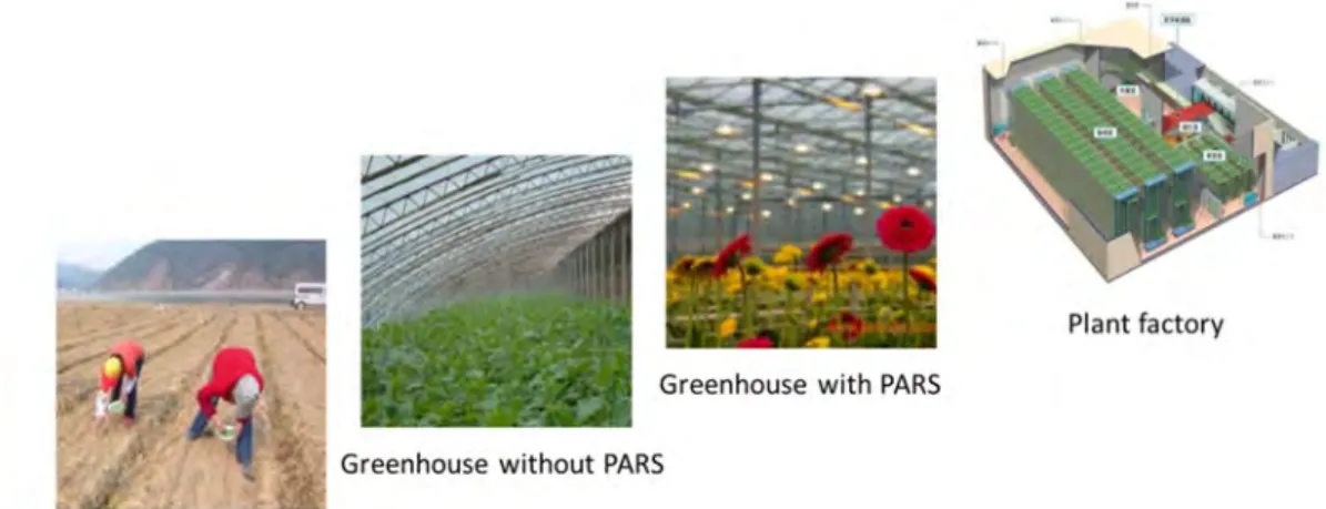
The development of agricultural farming went through 4 stages: traditional uncovered farmland, greenhouse without PARS, greenhouse with PARS and plant factory (Figure 1-5). CEA is the trend to make agriculture from open fields to indoor systems, which will become a competitive and attractive industry.
Figure 1-5 The development of agricultural farming Reasons to develop CEA
The following global crises facing the planet make CEA more and more popular. A. A growing population in the world
B. Increasing material needs C. Declining agricultural resources
D. Rapidly growing issues of environmental pollution E. Climate change and disasters increasing year by year F. Difficult to guarantee agricultural production systems G. Prominent food security issues
H. Renewable bioenergy in demand I. The challenge of urbanization.
Characteristics of CEA
Traditional agriculture depends on the natural environment as well as pesticides, chemical fertilizers, antibiotics and other chemicals, but CEA will gradually get rid of these shackles, and ultimately access to high-quality, high-yield, energy efficient and environmental friendly manners [31, 32].
CEA is the combination of physical techniques and agricultural production. The physical factors can regulate growing environment of plants and their growth, such as temperature, humidity, CO , light, nutrients, etc. [33, 34]. It is also a high input high output industry and a new production system, which requires equipment, technology and plants be highly correlated. Biological and physical factors are controlled to maximize yield and eliminate the use of toxic and harmful chemicals.
The new technologies are the leader and driving force for development of modern agriculture. These include biotechnology, information technology, water-saving irrigation technology, farming techniques, etc. Modern agriculture makes these technologies become highly intensive industries [35].
The application of agricultural science and technology, firstly, can increase the production units, secondly, can improve the quality of agricultural products, thirdly, can reduce labor intensity, and fourthly can save energy and improve the ecological environment by increased resource utilization and sustainable development capacity. Because the global
shortage of resources has become increasingly prominent, agricultural products will become more important, so that the benefits of agriculture may become one of the most promising industries. Modern ecological agriculture has the mission of resource conservation and sustainable development, improving the quality of human life and the living environment.
1.2.2
Commercial greenhouse
The agriculture sector faces the daunting challenge of providing adequate food and other necessities. Unfortunately, there is limited scope for the expansion of cultivated land, and the emerging threat from climate change and other disasters make the task even more challenging [30, 36]. People desire and look for an environmentally friendly and efficient production methods to confront seasonal changes, bad geographical locations, natural disasters, severe weather conditions and so on, so greenhouse has been developed with protection facilities.
Greenhouse is a structure with walls and roof made chiefly of transparent materials, in which plants requiring regulated climatic conditions are grown [37]. There are several kinds of greenhouses such as plastic house, glass house, shade house, lath house, net house and multi-span greenhouse. According to the light conditions, there are greenhouse without PARS and with PARS (Figure 1-6). These structures range in size from small sheds to industrial-sized buildings, and the structures should be sealed heat insulation, but facilitate ventilation and cooling. Before, greenhouse was used in winter to provide a suitable temperature to cultivate plants, and it only used the sunlight as the single energy for photosynthesis. Later artificial light sources have been used as a supplemental light due to insufficient sunlight.
(a) (b)
Figure 1-6 Greenhouse without PARS (a) and greenhouse with PARS (b) (From: http://www.greenhomegnome.com/types-greenhouses-usage/)
Greenhouses are concentrated in two geographic areas: in the Far East (China, Japan and Korea) are grouped 80% of the greenhouses in the world, and in the Mediterranean Basin about 15%. Global area occupied by greenhouses in 1980 was 100,000 hectares, which had increased to 450,000 hectares by 1998; an annual growth close to 20%. Asia accounts for 66% of the area, Europe for 26%, while in America and Africa both account for 4%. By the beginning of the 21st century, the global area of protected crops was around a million hectares; with China accounting for an estimated 700,000 hectares, another 80,000 cultivated in South Korea, Europe and America. Growth is slow in Europe, but in Africa, America and the Middle East, growth ranges from 15 to 20% annually. Notably, China has grown from 4,200 hectares in 1981 to over two million hectares today (30% annually), and
has been the country with the largest area of greenhouses. The total areas in major greenhouse production countries are shown in Figure 1-7.
Figure 1-7 Protected crops in the world: over 3 million hectares [30]
Some commercial greenhouses have high-tech production facilities for vegetables or flowers. The greenhouses are filled with equipment including screening installations, heating, cooling, lighting, and may be controlled by a computer to optimize conditions for plant growth [38].
1.2.3
Industrial plant factory
In order to have more living space people construct high-rise buildings, similarly, in order to meet the needs of material life as well as an ecological environment, people can also design plant factories with artificial lighting (Figure 1-8).
Figure 1-8 Plant factory with artificial lighting (From: http://www.odmled.com/news/483.htm) A plant factory is an indoor vertical farming system for efficient quality food production. It provides information on a field that contribute to offset the threats of unusual weather and shortages of land and natural resources [39]. Plant factory is also a closed plant cultivation facility with physical protection technology, environmental control technology and biological technology as the core technologies, which can control plant diseases and insect pests without using pesticides or other chemicals, and protect the plants from physiological disorders. It mainly includes photosynthetic system, humidity system, temperature system, air circulation system, water and fertilizer system, breeding systems, monitoring and control center, and internet of things (IOT) system (Figure 1-9). The production process is highly intensive. Plant factory has been internationally recognized as an advanced stage of
agricultural development; it is an inevitable trend in the development of protected horticulture; it is also one of the most important marks to measure the level of agricultural technology development in the countries [40, 41].
Figure 1-9 The systems of plant factory for production with the core techniques
There are many reasons why plant factory is becoming a new hot spot for investment: A. Environmental pollutions lead to food safety issues. For example, the abuse of pesticides, insect
repellents, fertilizers and hormone; heavy metal and water pollution caused by industry. B. Traditional agriculture cannot adapt to climate change such as water scarcity and land
desertification
C. Urbanization has brought urban population increase, so land resources are dwindling. The demand for agricultural products is on the increase each year.
D. Logistics costs of urban vegetable supply become higher and higher. The prices of agricultural products also rise a lot.
E. The costs of LED application are gradually declining; multi-band LED light is available.
Plant factory production systems have a higher controllability and stability compared with greenhouse. It has a significant value in solving the problems of world resources, environment, food security, climate change and extreme weather disasters. In order to create the best environmental conditions and get more efficient production, some new characteristics of plant factory are presented as follows.
A. Plant factory is a closed plant production system, so the growing environment is not or little affected by the natural climate and soil fertility. Unlike greenhouse, it does not use sunlight
and has no transparent material as a cover. In fact, plant factory is a technology-intensive factory for plant growth.
B. Plant factory has the ability to achieve constant production all year around, and the powerful productivity is up to 100 times that of field production [42], especially vertical and multi-layer farming systems with the artificial lights, which can greatly enhance the photosynthetic efficiency and land utilization efficiency.
C. The quality of agricultural products such as concentrations of phytonutrients can be enhanced through manipulation of the growing environment, especially light quality. Moreover, the products are pesticide-free, and the bacterial load is generally less than 300 CFU/g (colony forming unit/gram), which is 1/100 to 1/1000 that of field-grown produce [39], so the products have a longer shelf life and do not need to be washed before eating.
D. Plant factory incorporates high technology and modern science, and can realize precise control of micro-climate by climate controllers and computers. The environmental factors can be manually set and controlled including light, temperature, humidity, wind, pH, carbon dioxide, nutrients and so on. The facilities can be adjusted or programmed according to the climate needs of plants in different growing stages, even realize the automatic control of the environment for specific species. That is to say high resource use efficiency can be achieved with minimum emission and environmental effect.
E. Plant factory can be built anywhere because neither sunlight nor soil is needed, instead of them are artificial light technique and soilless culture (hydroponics, deep flow technique (DFT), nutrient film technique (NFT) and aeroponics culture) [43]. If plant factory is built near urban areas, it is more convenient and reduce transportation costs.
F. In theory any plant can be grown in a protected environment. Plant factory has the advantage in the cultivation of plant breeding and leafy vegetables. However, economic profitability, management and production cycles have determined that high value cash crops and rare medicinal, vegetables, cut flowers and medicinal herbs are grown this way, such as Dendrobium officinale Kimura et Migo [44]. What plant factory should do is to create appropriate growth environment for specific species.
G. Intelligent plant factory can reduce human activities on the production space of interference and pollution. Automatic production includes: controlling environmental factors, fertilizer supply and deployment, seeding, transplanting, harvesting, etc.
Intelligent control of production factors is the most essential features of plant factory. Development of science and technology laid a good foundation. It is important to note the key points such as the proposal of mineral nutrition theory, soilless cultivation techniques, environmental factors and nutrient monitoring based on the development of computer and sensor technology, and the development of semiconductor lighting technology. Currently, almost all environmental factors of plant factory achieve automatic detection, storage, analysis and intelligent control [41].
Plant factory conforms to the essential connotation of modern agriculture, which is equipped with science and technology. Modern organizational management methods are used for agricultural socialization and commercialization. Especially, information network technology is also used to promote the application of modern elements in agricultural production, narrow the distance between production and the market, greatly expand the space for development of agriculture, and enhance comprehensive services in the supply of agricultural materials, technical guidance, financial services, and actively promote the
innovation of agricultural and industrial systems. Plant factory has become a strong competitive industry in the national economy.
1.2.4
Significances of CEA
CEA is an innovative production method and have a potential to solve social problems, assure a sustainable agricultural system and eliminate hunger and malnutrition. It is also the most important indicator of ecological agriculture. Agricultural industry itself can become a good cycle of the ecosystem and become sustainable development.
There are many significances to develop CEA [41, 44].
A. Efficient production of renewable bio-energy can supplement fossil fuel depletion.
B. Appropriate scale operation and intensive production can be adopted for efficient using various inputs, including water, electricity, plastic sheeting, fertilizer, seeds, agricultural machinery, etc. So it can reduce the emission of pollutants and improve the ecological environment.
C. Plant growth is less or no influenced by the external environment and climate, so it is able to solve the problem of national food security, improve the quality of agricultural products, human health and nutrition, and less or not use chemical fertilizers, hormones and pesticides. D. Full-year production can realize a higher overall productivity, including higher land utilization
efficiency and labor productivity.
E. Make agriculture a highly commercialized industry with high agricultural commodity rate (>90%), economic efficiency and market competitiveness. Reduce production costs in order to meet the market demand. Reduce rural poverty and contribute directly to higher incomes and the local economy. Gradually lead the people out of poverty and hunger.
F. Meet the new demand for every kinds of food. For example, food in different seasons and high value products can be available.
G. Provide life-support for scientific explorations on extreme environmental conditions, such as oceans, deserts, mountains, Arctic and Antarctic, space station, Moon, Mars, etc.
1.3
Light sources & lighting systems for CEA
1.3.1
Light sources
There are three major light source technologies: incandescence (incandescent lamp), electrical discharge (fluorescent, HID), and solid state light sources (LED, OLED). The first two are known as “legacy” technologies, and the third is considered as modern technologies. In order to choose the best light source for plant growth, it is necessary to understand the history, characteristics, luminescent mechanism and applicability of typical light sources.
Legacy light sources 1.3.1.1.a Incandescent lamp
An incandescent lamp, also called incandescent light bulb or incandescent light globe, is known as the first generation of artificial light source, which was one of the most important inventions since the fires, candles and oil lamps. The first reliable and commercial incandescent lamp was invented by Thomas Edison in 1879 (Figure 1-10), which has already been 137 years of history. It had become a symbol of innovation. It was widely used in
domestic and business life before, but now it has been gradually replaced by lamps of higher efficiency.
(a) (b)
Figure 1-10 Thomas Edison with the first incandescent lamp (a) and the typical structure of incandescent lamp (b)
Incandescent lamps include standard incandescent, halogen lamps and reflector lamps. They work by sending electric current through a resistive filament inside a glass or quartz bulb evacuated or filled with inert gas, and heating the filament to a high temperature until it glows with visible light (incandescence). Normally, materials will glow before reaching a melting point. But most materials will melt and cannot make a good filament at a high temperature, so the materials of filament had been the major bottleneck technique [45, 46]. The history of the incandescent lamp was focused on the development of filament types.
From 1802 to 1880s, platinum and iridium filaments were first used for an incandescent lamp. However, blackening on the upward side of the bulb blocked light output. From 1860s to 1883, carbonized threads and paper were developed. Edison doped out a solution to create a pure vacuum with a Sprengel pump by heating up the bulb. He managed to put carbonized threads inside a vacuum and successfully made his first practical light bulb. The breakthrough increased lamp life to 600 hours, so the incandescent lamp was commercially available in 1879. The era of metallic filaments was from 1902 to 1911. Tantalum was the first metal filament and became the king from 1904 to1911. Like tungsten it has a very high melting point, so it can be heated to incandescence with a lower energy and emitted a greater brightness. But after 1909, sintered tungsten lamp became more prevalent. The invention of a ductile tungsten finally terminated the era of tantalum. From 1904 to 1907, there was another filament called GEM Lamp Metallized Filament. A carbon filament was baked at 3000 ℃ to make it like a metal. The efficiency was also improved by 25%. In 1904 sintered tungsten was invented and developed. The lamp efficiency was improved by 100% until 1907.
In 1912 three important improvements were developed to the bulb: an argon and nitrogen-filled bulb, a tight coiled filament, a thin molecular hydrogen coating on the inside of the bulb. In 1921 double coiled filament was developed to further improve luminous efficacy. In 1925 a frosted etched bulb and later in 1947 a silica coating on the inside of the bulb were invented. These advancements helped diffuse the light, reduce glare with only 3-5% loss in light output. All of these dramatically improved the bulb.
In 1955 the first halogen lamp was developed. The halogen lamp has been developed based on incandescent lamp. The striking difference is the filling gas. Halogen lamp contains a
halogen gas (bromine or iodine) in the bulb. The tungsten atoms chemically unite with the halogen gas molecules and when the halogen cools, the tungsten is redeposited back on the filament. The process is called the halogen cycle, which has an ability to stop the blackening and slows the thinning of the tungsten filament. This technique lengthens life of the bulb and allows tungsten to safely reach higher temperatures.
From 1908 to the present, tungsten proved to be a superior material for a long lasting light bulb over any other material. Ductile tungsten filament has been the final selection due to its efficiency, durability, bulb life and easily coiled to increase brightness. The invention was also widely used in many other lamps including the fluorescent, halogen, metal halide, mercury vapor, etc. Previous sintered tungsten filaments had been efficient, but brittle and not practical to use.
Although the incandescent lamp has been in the average household for more than 130 years and improved many times, its future is less optimistic. In the last two decades a major initiative to develop more efficient lightbulbs has replaced incandescent lamps in many applications by other types of electric light, such as fluorescent lamps, compact fluorescent lamps (CFL), cold cathode fluorescent lamps (CCFL), high intensity discharge (HID) lamps, and light-emitting diode (LED) lamps. There has been clearly prohibition to use incandescent lamps by many countries according to the rule: phase out of incandescent lamps in 2008 [47].
1.3.1.1.b Fluorescent lamp
Fluorescent lamp is considered as the second generation of artificial light source, which had the greatest development in lighting since the incandescent lamp. There are three main types of fluorescent lamps: cold cathode, hot cathode and electroluminescent lamps [46]. They all use phosphors excited by electrons to create light. The difference is that electroluminescent lamps use fluorescence. It has been widely used in hotels, offices, shops, hospitals, libraries, advertising, family and plant cultivation for 78 years of history since commercial use. Besides, it is also a backlight for LCD displays.
The cold and hot cathode lamps consist of a glass discharge tube filled with an inert gas (usually argon) at low pressure, fluorescent coating on the inside, a tungsten electrode in each side, a ballast only or ballast with starting switch (Figure 1-11). Fluorescent lamps work by ionizing mercury vapor in the glass tube. This causes electrons in the gas to emit photons at UV frequencies. The UV light is converted into standard visible light using a phosphor coating on the inside of the tube. At the beginning, it was a great challenge to start the arc in the discharge tube [48].
The ballast was used to regulate AC current without destroy the lamp. In order to get the lamp started, there must be a spike of high voltage to start the arc, because argon gas itself is a resistance, the colder the gas, the higher the resistance. To reduce the danger and difficulty for a high voltage, preheat the lamp is figured out by using a starting switch. Now there are several ways to start the lamp such as preheat, instant start, rapid start, semi-resonant start and programmed start.
Take the most common preheat way as an example. First, Figure 1-11 shows the AC current ( ) passes through the ballast, one tungsten electrode, starting switch and the other electrode in order. At the same time the current warms a bimetallic strip of a small neon or argon lamp inside the starter, and preheats and ionizes some of the gas in the discharge
tube. Second, the preheat leads to thermionic emission, and the free electrons ionize the argon gas in the tube. Third, when the starter switch gets warm enough, the bimetallic strip flips the other way and bypasses the small lamp inside the starter. As a result, the open circuit can lead to magnetic field collapse of transformer in the ballast, and produce a high voltage to start the arc ( ). After that, the mercury will be vaporized and ionized in the arc tube and create UV light. The phosphors coating inside the glass tube will convert the light into useful visible light.
Compared with DC current, AC current is good for fluorescent lamp to protect tungsten electrodes and emit a nice uniform brightness on both sides. So it can last a long time with AC current.
Figure 1-11 The basic structure and work principle of preheat fluorescent lamp 1.3.1.1.c High intensity discharge lamp
High intensity discharge (HID) lamps are known as the third generation of artificial light source. They are also a type of electrical gas-discharge lamp mainly including metal halide, high-pressure sodium, low-pressure sodium and mercury-vapor lamps. HID lamps are applicable for large square.
HID lamps produce light by striking an electrical arc across tungsten electrodes housed inside a transparent and specially designed fused quartz or fused alumina arc tube. This tube is filled with both gas and metal salts. The gas aids in the arc's initial strike. Once the arc is started, the metal salts are heated and evaporated to produce the light, forming a plasma. Like fluorescent lamps, a ballast is necessary for HID lamps to start and maintain the discharge arc [49, 50].
Metal halide (MH) lamp and high pressure sodium (HPS) lamp are the typical HID lamps. They will be mainly introduced in this part.
A. Metal Halide Lamp
Metal halide (MH) lamp is a kind of HID light source. It is popular due to its great color rendering index and high efficiency. The most prominent applications are streets and squares, stadiums, industrial buildings, exhibition centers, shopping malls, docks and railway stations.
Stabilizing the MH lamp arc and color was the main problem in the history. The lamp uses mercury vapor to create the powerful light but includes other halide salts (fluorine(F), chlorine (Cl), bromine(Br), iodine(I) and astatine (At)) to improve the color. A halogen is a monovalent element which readily forms negative ions. A halide is a chemical compound of a halogen combined with an electropositive element.
The argon gas strikes an arc at a low temperature, so the current can pass through the starting electrode to the main electrode (Figure 1-12). The initial arc is weak, and it can heat up the mercury into a vapor. So the more molecules of the gas ionize, the more current passes through the arc. When the arc reaches the other main electrode, the current will stop flowing through the starting electrode. Meanwhile, the halides vaporize and dissociate. The metal atoms diffuse away from the arc and recombine with the halogen before they damage the silica or electrodes. Finally, the lamp is fully warmed up and produces its white light [51-53].
Some critical materials are used for MH lamps. Under a high temperature and pressure, fused quartz is adapted due to a high melting temperature instead of the silica in normal glass. To increase the lifetime, tungsten made electrode is also treated with radioactive thorium. Borosilicate glass is used in the outer envelope to insulate as well as filter out UV-B radiation. Molybdenum is used in the seal of the discharge tube to avoid corrosion and high temperature.
Figure 1-12 The structure of metal halide lamp B. High pressure sodium lamp
High pressure sodium (HPS) lamp is a kind of HID lamp with high lumen output and high efficiency. It has been widely used in airports, industrial and mining enterprises, parks, highways, squares, streets interchange and plant grow. The basic structure of HPS lamps is shown in Figure 1-13.
Figure 1-13 The structure of high pressure sodium lamp
The sodium lamp with a higher pressure in the arc tube could achieve a higher efficiency. Which kind of material could stand the corrosive effects of sodium under the high pressure and temperature is the main problem. Later, aluminum oxide ceramic was adopted. HPS lamps consist of a narrow arc tube supported by a frame. Sodium, xenon and mercury are used inside the arc tube. The lamp starts an arc through xenon gas by a pulse of high voltage via a ballast. Then the arc heats up the mercury like MH lamps. The sodium is the last material to vaporize (over 240℃). The mercury helps add a blue light to the pure yellow of the sodium. The sodium is mixed with other impurities to create a nice white light [54, 55].
Solid state light sources 1.3.1.2.a Light Emitting Diode
Solid state light sources are a kind of Modern light sources, including Light Emitting Diode (LED) and Organic Light Emitting Diode (OLED). LED is known as the fourth generation of artificial lighting source, which has about 60 years of history from the first infrared LED patented in 1961 [56]. In 1962, the first practical visible spectrum LED was developed. The first high-power (1W) LEDs were developed in the late 1990s. It is a new technology and has been developed rapidly in the last decade. Early LEDs emitted low-intensity infrared or red light and often used as indicator lamps instead of small incandescent bulbs. Modern LEDs are available in a broadband wavelength across the ultraviolet (250-380 nm), visible (380-760 nm) and infrared (760-1000 nm), which have been becoming popular due to their high efficiency and brightness. Nowadays, LEDs are used in anywhere, such as indicators and signs, LCD backlight, displays, indoor and outdoor lighting, traffic lights, greenhouse lighting, etc.
LED is a small semiconductor light source (less than 1 mm2), including a two-lead p–n
junction, reflectors, phosphors or integrated optical components to create light and shape its radiation pattern. Figure 1-14 (a) shows one structure of high power LED [57]. The p–n junction is a boundary between two types of semiconductor material inside the same crystal. Like the common diode the p-n junction only allows electrical current to pass through in one direction (from positive to negative), which is called forward-biased. The color of the light emitted is determined by the semiconductor materials and the impurities of the junction [58].
An electron hole exists where an atom lacks electrons (negatively charged) and therefore has a positive charge. With a suitable voltage or current, electrons are able to recombine with electron holes within the semiconductor, releasing energy in the form of photons. This effect is called electroluminescence. The color of the light corresponds to the energy of the
photon, which is determined by the energy band gap of the semiconductor (Figure 1-14 (b)) [49, 58-60].
(a) (b)
Figure 1-14 Structure of high power LED (a) and light principle of P-N junction (b)
The total cost of a lighting system includes the initial purchase price, the cost of electricity and cost of replacement. In the past, LEDs were often too expensive for most lighting applications. Even though the price of LEDs has significantly decreased over the last few years, it is still much higher than the price of legacy lighting sources. However, this higher initial cost can be offset by the longer lifetimes and better energy efficiency [61]. Yet since the life cycle savings are not guaranteed at the time of lighting system selection, higher initial costs are still an obstacle to the acceptance of LED lighting. According to a study by Samsung, the selling price of a white LED lighting system needs to decrease by 50% in order to make LEDs more competitive with fluorescent lamp systems over the next 4–5 years [62, 63].
1.3.1.2.b Organic Light Emitting Diode
Organic light emitting diode (OLED) is designed by a layer of organic electroluminescent material with p-n junction sandwiched between two electrodes. One of the electrodes is transparent so the photons can escape. The shape of OLED is very similar with electroluminescent (EL) lamps, but they are different. OLED uses organic (carbon) molecules in the layer to emit light, but EL lamps are only excited by phosphor materials to make light. Although the OLED is not as bright as EL display or liquid crystal display (LCD) currently, OLED has been considered as one of the most promising technologies for future displays. OLED has an advantage to better display blacks without a cold cathode fluorescent backlight used for LCD. The OLED display can also provide better contrast ratios than LCD. OLED may also be made into a thin flexible material which could roll up like a newspaper (Figure 1-15 (a)) [60, 64].
Early OLEDs had one layer of organic material between two electrodes. Modern OLEDs are bi-layer, they have an emissive layer and conductive layer sandwiched between two electrodes (Figure 1-15 (b)). When an electric current passes from the cathode to the anode, charges are injected in the organic material, holes from the anode and electrons from the cathode. The holes jump to the emissive layer along the border of the two layers where they recombine with electrons (this place is the p-n junction). After diffusion, the exciton recombines. Light is emitted when the electrons join the holes and a photon is emitted. Polymer LEDs and carbon nanotube technology can expect a lower cost due to the material
and less part assembly. However, further study should be done to reach full potential of OLED [60, 64-66].
(a) (b)
Figure 1-15 OLED display (a) and the basic structure of OLED (b) [60] Comparison of different light sources
There are four generations of different artificial light sources (Figure 1-16), and each evolution has made great progress. Compared with fluorescent and incandescent lamps, HID lamps have a higher visible light in contrast to infrared per unit area of envelope. Miraculously, LED has more obvious advantages than legacy light sources. First, LEDs can directly convert the electrical energy to light rather than producing lots of heat by a superheated filament, ionized gas, or arc discharge. So they can save up to 90% energy compared to a legacy bulb with the same light output. Besides, the mean time to failure (MTTF) of LED can be up to 10 times longer than that of legacy light sources (see Table 1-1), avoiding the hassle of frequent changing of light bulbs. This significantly reduces waste but also saves money in the long term. Besides, various color and color temperatures from 2700 to 12,000K are available, as well as saturated colors. They are solid-state devices, which are much more robust than any glass envelope lamp and contain no hazardous materials like fluorescent lamps.
(a)
(b)
Figure 1-16 Artificial light sources: legacy light sources (a) and low and high power LEDs (b) Table 1-1 Key characteristic comparison of different light sources
Name Optical spectrum Efficacy (lm/W) Lifetime (MTTF) (hours) Color temperature (kelvin) Dominant color Color rendering index
Incandescent Continuous 4–17 2000 750- 2400–3400 Warm white (yellowish) 100
Halogen Continuous 16–23 3000–4000 3200 Warm white (yellowish) 100
Fluorescent Mercury +Phosphor Line spectrum 52–100 (white) 20000 8000- 2700–5000
White (various color temperatures), as well as saturated colors available 15–85
Sulfur lamp Continuous 80–110 15000-20000 6000 Pale green 79 High pressure sodium Broadband (Pressure dependent) 55–140 10000-40000 1800–2200 Pinkish orange 0–70 Low pressure
sodium Narrow line
100–
200 18000-20000 1800
Yellow, no color
rendering 0
LED Die(s) emission and phosphor (for white LED only)
Up to 300 (Cree) 35,000– 100,000 Various white from 2700 to 12000 Various color temperatures, as well as saturated colors Up to 95 (white) OLED Broadband (RGB for white) 54-124 30,000– 100,000 Various white from 2300 to 9700 Ditto (white) 74-90
Electrodeless Mercury line +Phosphor (white) 70–90 80,000–100,000
Various white from
2700 to 6000
Ditto (white) 70–85
Note: CRI definition is not always valid for LED technologies.
1.3.2
Artificial light and plants
Plant Artificial Radiation Sources (PARS), also called greenhouse light or grow light, is a kind of supplemental light or full light to promote photosynthesis of plants. The history of plant cultivation by electric light has been over 150 years. Like the history of artificial lighting, PARS has undergone four stages: incandescent lighting, open arc lighting, enclosed gaseous discharge and solid-state lighting. Now PARS has been widely used in greenhouse and plant factory [67].
The lack of illumination time, insufficient light intensity and light quality are the common phenomenon for traditional glasshouse and other similar facilities. Due to changes of seasons and weather conditions (overcast, rain, snow, fog, haze, etc.), in addition to air pollution, drifting and other negative factors, there is insufficient sun light in greenhouse. This causes serious reduction of output even crop failures. Besides, the sunlight into greenhouse reduced by 20%-50% because of the greenhouse structure and the block of films. Low light intensity seriously affects the yield and quality of horticulture. Therefore, only using sunlight cannot get enough photosynthesis to meet the needs of crop growth and quality. Supplemental lights are urgently needed for photoperiod control for the plants in different regions [41]. PARS is essential for artificial light cultivation. Precision intelligent light environment regulation is a fundamental determinant for plant tissue culture, plant factories and edible fungus factory under artificial light.
![Figure 1-2 The numbers and shares of hunger and undernourished people in the world [2] Food safety problems](https://thumb-eu.123doks.com/thumbv2/123doknet/2180281.10477/23.892.151.807.188.499/figure-numbers-shares-hunger-undernourished-people-safety-problems.webp)