BIOREFINE
Recycling inorganic chemicals from agro- and bio-industrial
waste streams
Project/Contract number: 320J - Biorefine
Document number: BIOREFINE – WP2 – A7 – P1, 2, 5 – D
Techniques for nutrient recovery from household and industrial wastes
Date: 17/07/2015
Start date of project: 1 May 2011 Duration: 56 months
Authors: M. Alonso Camargo-Valero, L. Bamelis, L. De Clercq, F. Delvigne, E. Meers, E. Michels, D. R. Ramirez-Sosa, A. Ross, H. Smeets, C. Tarayre, N. Tarayre, P. T. Williams
Authors’ Institutions: DLV InnoVision, Gembloux Agro-Bio Tech, Ghent University, University of Leeds
Project funded by the European Regional Development Fund through INTERREG IV B Dissemination Level
PU Public x
PP Restricted to other programme participants (including the Commission Services) RE Restricted to a group specified by the consortium (including the Commission Services) CO Confidential, only for members of the consortium (including the Commission Services)
Table of contents
Table of contents ... 2
1 Glossary ... 3
2 Introduction ... 6
3 State-of-the-art nutrient recovery techniques from household and industrial wastes ... 6
3.1 Composting of organic domestic waste ... 6
3.2 Composting combined with energy production ... 13
3.3 Anaerobic digestion – Rainbarrow farm plant ... 22
3.4 Anaerobic digestion – Nestlé’s Fawdon factory ... 25
3.5 Nutrient recovery from landfill leachate ... 27
3.6 Phosphorus recovery from sewage sludge: general points ... 28
3.7 Wet chemical treatment of sewage sludge ash ... 32
3.8 Production of struvite from sewage sludge: PHOSPAQ® process ... 35
3.9 Production of struvite from sewage sludge: OSTARA® process ... 41
3.10 Phosphorus precipitation from industrial wastewater ... 44
3.11 Production of pellet fertilizer from sewage sludge ... 46
3.12 Incineration and metal recovery from household and industrial wastes (designed by SELCHP, UK) ... 49
3.13 Incineration and metal recovery from household and industrial wastes (designed by LondonWaste) ... 54
3.14 Removal of heavy metals from sludge and sediments ... 57
3.15 Removal of metallic compounds from ashes (IPALLE, Belgium) ... 63
4 List of useful contacts ... 68
1 Glossary
AD: Anaerobic Digestion Al: AluminiumAPC: Air Pollution Control BTF: Bio Trickling Filter CaO: Calcium oxide CH4: Methane
CHP-unit: Combined Heat and Power unit CO2: Carbon dioxide
CSDU: Centre de Stockage des Déchets Ultimes C/N ratio: Carbon to nitrogen ratio
DM: Dry Matter
EBPR: Enhanced Biological Phosphorus Removal Fe: Iron
FeCl3: Iron (III) chloride
GAC: Granule Activated Carbon HC: Hydrocarbon
hrs: Hours H2O: Water
H2S: Hydrogen sulfide
kg/d: Kilogram per day
kg/m³.d: Kilogram per cubic meter per day kg/t: Kilogram per ton
kg CaO/t: Kilogram of calcium oxide per ton kg K2O/t: Kilogram of potassium oxide per ton
kg MgO/t: Kilogram of magnesium oxide per ton kg N/t: Kilogram of nitrogen per ton
kt P/y: Kiloton of phosphorus per year kV: Kilovolt
kW: Kilowatt
kWe: Kilowatt electric kWh: Kilowatt hour
kWh/d: Kilowatt hour per day m³: Cubic meter
m³/d: Cubic meter per day m³/h: Cubic meter per hour
MAP: Magnesium Ammonium Phosphate mbar: Millibar
mg/L: Milligram per liter mm: Millimeter
MWe: Megawatt electric
MWh/d: Megawatt hour per day MWth: Megawatt thermal µm: Micrometer
µS/cm: Micro-siemens per centimeter N: Nitrogen
NaOH: Sodium hydroxide Nm³: Normal cubic meter
Nm³/h: Normal cubic meter per hour N2: Molecular nitrogen
P: Phosphorus
Sm³/h: Standard cubic meter per hour t/y: Ton per year
UASB: Upstream Anaerobic Sludge Blanket UK: United Kingdom
VFG waste: Vegetable, Fruit and Garden waste WWTP: Wastewater treatment plant
2 Introduction
Domestic and industrial waste streams such as wastewater and organic waste contain a lot of valuable macronutrients (e.g. nitrogen, phosphorus and potassium) and micronutrients (e.g. heavy metals and rare earth elements). In the past, most of these materials were just landfilled or discharged, causing environmental damage and losses in nutrients. An advanced system of domestic waste collection, sorting and recycling has been applied for years in most European countries, leading to a gradual shift to sustainable resource management. Furthermore, industry is making efforts to gain a green image and invest in recycling and recovery techniques.
The Interreg IVB project BioRefine aims at facilitating the shift to a circular, bio-based economy in North Western Europe by using an action-oriented approach consisting in providing applied technological solutions for improved recycling and recovering of valuable minerals from different wastestreams. This report gives an overview of the most popular techniques (full-scale or under development) for nutrient recovery applied to solids and liquids of domestic or industrial origin.
3 State-of-the-art nutrient recovery techniques from household
and industrial wastes
Different techniques can be applied to household and industrial wastes. Here, we will consider different types of wastes, including sewage sludge, leachate from landfills and other organic materials. Liquid and solid states will be considered.
3.1 Composting of organic domestic waste
3.1.1 General context
The vegetable, fruit and garden (VFG) waste left over by households can be composted on a small scale at home (the so-called small cycle) or selectively collected and composted on a large scale. The collection can be organized by inter-municipal waste agencies, as is the case in Belgium, from door-to-door or at the communal waste recycling depot. Some regions collect both VFG and green waste (from parks, gardens, nature reserves, roadside verges, etc.) together, others collect them separately (Vlaco vzw, 2015). Vegetable, fruit and garden (VFG) wastes can also be collected selectively and used for the production of heat and electricity through anaerobic digestion. From an energetic point of view, this is the most effective route, since both energy as heat and electricity and a valuable residual product, digestate, are developed. Digestate can be composted and results in a sufficiently hygienized product. In Flanders, the quality of the compost obtained is certified by the Flemish Composting Organization (Vlaco vzw), which means that quality is ensured and so, the compost can easily be marketed. Besides composting, the digestate can also be processed by mechanical separation, drying, filtration, etc. as described in the BioRefine report ‘Recovery techniques from digestate and digestate derivatives’.
3.1.2 Description of the technique
The professional composting process consists of different processing steps. Pre-treatment is necessary for effective composting. This step includes mixing, size reduction and piling, and is shown in Figure 1. The optimal shape of the pile depends on the composting system. In general, the volume has to be large enough to prevent cooling and drought at the edges. The composting process is conducted by bacteria and fungi already present in the organic material. As long as there is oxygen inside the pile, the microflora and -fauna compost very intensively ,causing a temperature rise up to 50-77 °C. During the process, oxygen is used, which results in an incomplete oxidation of the carbon compounds, causing the formation of fatty acids and other organic acids. This pH decrease causes the process to slow down. By turning over the pile and if necessary moisturizing it, more oxygen is brought into the system and the water content is optimized, causing decomposition. A major advantage of high temperature in combination with high moisture content is that weed seeds lose their germinating power. In this way, a ‘hygienized’ product is obtained. In general, the composting of green waste takes place in open air, while the composting of vegetable, fruit and garden waste takes place in an enclosed space (Vlaco vzw, 2015).
In a third phase, the ripening process, the microfauna causes a structural and biological transformation of the material in the compost and plays a role in the mixing process of organic and mineral compounds. Depending on the process, the post-ripening phase lasts from 3 weeks to 3 months. The last phase, called post-treatment, includes the refinement of the compost, which consists in sifting unusable parts and splitting the compost into different granulometric fractions depending on the end-use. In practice, this is done through drum or star sieves. The benefit of sieving is that possible contaminants (rocks, metal, plastic, etc.) remain in the sieve. At least one part of the sieve remainders will be transferred to the beginning of the process. In this way, enough structural material remains in the process and the starting material is inoculated with already active organisms (Vlaco vzw, 2015).
The process parameters of the composting process are monitored with great accuracy. The regulation of humidity, temperature (around 55 - 70 °C) and ventilation is completely computerised. It is important to keep these conditions as optimal and stable as possible to ensure a decent bacteriologic composting process. In the case of the process used by EcoWerf, which collects the VGF-biomass from about 27 communities and has about 45,000 tons of VGF wastes composted each year in Flanders, the biomass is subdivided in different flows after the composting step:
- The biggest parts are not recuperated and will be disposed of as such after removal of the plastics.
- The smaller parts that fall through the first sieve will then be separated again by another sieve, which leads to two flows of materials:
o The biggest particles are those which have not completely finished the composting process and will therefore be used as inoculation material at the beginning of the pre-treatment. This also provides some structure to the fresh VGF wastes.
o The smallest particles (size of about and less than 1 mm) are the actual compost. At this stage, the compost is not ready for use, as it needs some further maturation.
Figure 1: Compost post-treatment.
Source: Vlaco vzw
3.1.3 Unit operations
The case described below is the set-up that is actually implemented at EcoWerf in Vlaams-Brabant (Belgium).
Reception / Storage volume (A)
The collected VGF will be dumped in this volume straight from the collection vehicle. In Flanders, a lot of VGF-composting units have developed a separate collection strategy, so there is no direct interference with other (non-organic) household wastes at this stage.
The presence of the VGF-biomass during this storage step is rather limited in time: in order to obtain an optimal composting process and prevent rotting and production of odorous gases, it is necessary to have the biomass treated within short notice (max. 48 hrs). The biomass is taken from these bunkers with grip arms and placed on belt conveyors for transportation between the different treatment steps.
Rotating sieve (B)
The sieve in the pre-treatment stage will do a first screening of the particles based on their size. A mesh-size of around 16 mm is usually used. The particles that fall through the sieve (< 16 mm) can go straight to the composting unit. The bigger particles will have to pass the crusher (see Unit Operation D) to decrease in size.
Ferro Detector (C)
Throughout the process, there are different places where the metals present in the biomass (e.g. knives, forks, etc.) are removed. This is done by using a magnet moving above the biomass (without actually touching it).
Crusher (D)
In the composting process, it is important to have a good surface/volume-ratio. As it is a microbiological process, the bacteria need the surface to cling to. An increase of the surface-volume ratio is obtained by crushing the bigger particles at the inlet.
Wooden branches remover (E)
This is a claw-shaped device that removes the branches that fell through the sieve from the biomass. The wood that is recovered here can be chopped and used as structure material in the composting unit or to fill the bio-filters for the odour treatment.
Composting (F)
Dependent on the type of biomass that is composted, one can decide between open-air composting and indoor composting. In the VGF’s composting applications, only indoor composting is in use. There are different ways to actually implement indoor composting, but the 2 most popular ones are done either in big halls or in tunnels. EcoWerf’s choice fell on indoor composting. The biomass will remain for about 5 weeks in the “composting zone” in which it is turned around on a weekly basis so as to allow “passive” aeration.
In order to obtain a highly effective bacterial activity, it is essential to use optimal process parameters: the right moisture content, oxygen level and temperature are of the utmost importance. In order to keep the moisture content at a high level, fluid is sprayed over the composting material – this can be fresh water, but whenever it is possible, it is the percolate liquid from the storage of the biomass that is used. The oxygen level is controlled by the ventilation of air through the biomass. As this ventilation greatly impacts the temperature of the composting biomass, the type of ventilation will depend on the temperature: if the biomass temperature is too
high, outside air will be ventilated through the composting hall. If it is too low, the inside air will be recirculated and used for aeration.
The air inside the composting hall has about 45°C and relative moisture of 100%. During the process, there will/can be an accumulation of odour in the air, which makes it necessary for it to be treated before being discharged to the open air. This is done by a bio-filter system filled with wooden material that is also collected by EcoWerf.
Plastics removal (G)
After the composting step, the plastic materials are removed by using a wind-shifter that uses the differences in density to lift out the plastics.
Sieve 1 - composted material (H)
In a first step, the separation of the bigger material from the composted material is achieved. This material contains too big particles for recirculation and will be disposed of “as such”.
Sieve 2 - composted material (I)
The next step is the separation of the actual compost from the inoculation material. All particles exceeding 10 to 15 mm in diameter are seen as inoculation material. Inoculation materials are “compostable” but not yet fully composted – this part of the biomass will be recirculated to the start of the process where it will be mixed together with the fresh incoming compost.
The smaller particles (< 10 to 15 mm) are considered to be actual compost, and will go through a maturation phase in order to ensure the stability of the material.
Maturation (J)
The final step of the composting process is the maturation phase, which lasts about 5 weeks. Here, the composting process slowly goes on in the most resistant parts of the biomass. This can be done either indoors or outdoors, though it is more common for it to be done in a covered area. The necessity of turning over the material remains for the sake of aeration. Some additional aeration and moistening might even be required to ensure the continuation of the process.
3.1.4 Process scheme
Figure 2: Process scheme of compost production.
Source: EcoWerf Ferro-detector (C) Reception / storage volume (A) Rotating sieve (16 mm) (B) VGF < 16 mm VGF > 16 mm Crusher (D) Sieved VGF Ferro-detector (C) Wooden branches remover (E)
Composting (F)
Plastic removal (G) Ferro-detector (C)
Sieve 1 (H) Smaller particles Bigger particles Sieve 2 (I) COMPOST INOCULUM AND STRUCTURE MATERIAL Maturation (J) Organic fraction from household waste
Metal waste Plastic waste Wood Biomass Percolate
3.1.5 Characterization of end product
Compost is a stable, hygienized and humus rich end product. It has a high content of stable organic matter and nutrients which become gradually available for plants. The composition of certified compost (according to Vlaco vzw) is shown in Table 1.
Table 1: Average composition of Vlaco certified compost obtained from VFG and green wastes.
VFG compost Green compost
Dry matter (kg/ton) 700 600
Organic matter (kg/ton) 250 200
Electroconductivity (µS/cm) 2500 1000
pH-H2O 8 8
Total nitrogen (kg N/ton) 12 7
Total phosphorus (kg P2O5/ton) 7 2.8
Total potassium (kg K2O/ton) 10 6
Total calcium (kg CaO/ton) 23 16
Total magnesium (kg MgO/ton) 5 3
C/N ratio 12 17
Germinative seeds Absent Absent
Pathogens Absent Absent
Source: Vlaco vzw
3.1.6 Useful contact(s) for further information
EcoWerf (Belgium)
Email address: see the website www.ecowerf.be
Vlaco vzw (Belgium)
3.2 Composting combined with energy production
3.2.1 General description
This second process is very similar to the previous one, but with an additional treatment step in between. In this case, the production of composting material from VGF waste will be combined with the production of renewable energy.
The plant that is described below is the plant of Méthavalor (Sydème) in Morsbach (France). This site has been operational since 2011 and treats about 42,000 tons of waste per year (385,000 inhabitants). About 32,000 tons of that waste consist of VGF waste disposed of by the inhabitants of surrounding regions, 5,000 tons of organic waste come from restaurants and similar businesses and the remaining 5,000 tons are green wastes. In the installation, 1 ton of VGF is converted to 100 m3 of biogas (which corresponds to 70 litres of gasoil) and 200 kg compost.
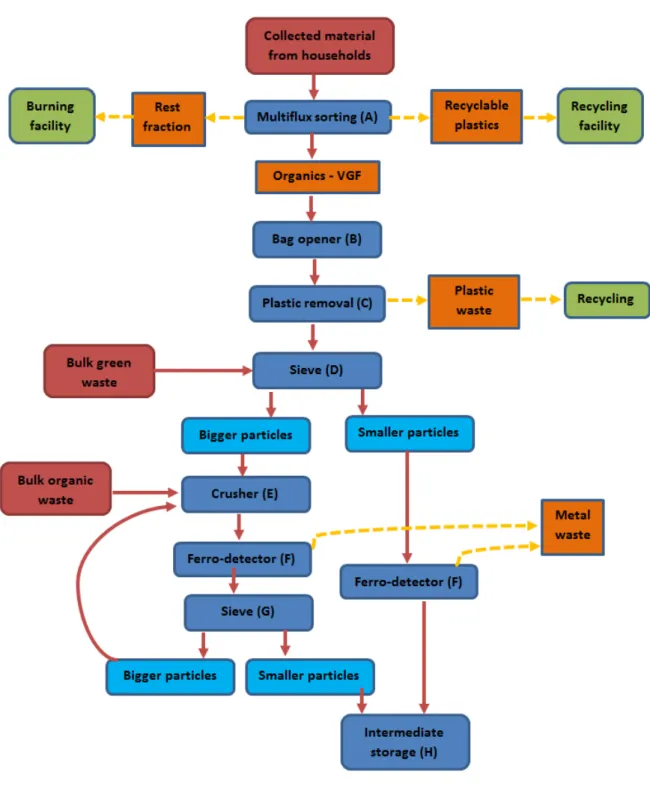
“Multiflux” sorting
The collection of the waste is slightly different from the traditional collection process: inhabitants have to put their wastes in plastic bags of different colours. Green bags are meant for biological waste (VGF), orange bags are for plastics and metals and blue bags are for all other types of domestic wastes. All these bags are collected simultaneously, which contributes to reducing collection expenses, since waste is collected only once instead of 3 times.
When all the bags are delivered to the site, they are sorted optically and directed to the sites they are meant for: the green bags are sent to the biomethane recovering unit, the orange bags are sent to “recyclable waste” stock (recycling is done on a different site), and the blue bags will be further treated (landfilled) at the “Centre de Stockage des Déchets Ultimes (CSDU)”.
Preparation of the biodegradable waste
After the separation of the green bags from the other waste, the preparation of the bio-waste for use in the biogas production starts. As mentioned above, there are several types of bio-wastes that will be processed in the biogas production: (1) VGF from households (green bags) (2) organic waste from restaurants, markets, etc. that arrive in bulk (3) green waste and (4) liquid waste (e.g. fats, food oil). Each type of waste is treated differently:
- VGF from households (in bags)
The first step is the opening of the plastic green bags. Once opened, the contents are spread on a moving sieve, while the plastic bags are removed by a wind-shifter. This way all the bags are collected and can be collected. All the material that gets through the sieve will be directed straight to the intermediate storage unit. The material that is oversized will first go through a shredder. The materials are also removed by magnets located above the conveyor belts.
- Organic waste (in bulk)
This type of waste is free of plastics as it comes straight from alimentary sources. The material is guided straight to the shredder system before being sent to the intermediate storage unit.
- Green waste
This type of waste is also crushed to smaller particles in the shredder. - Liquid waste
There is no actual pre-treatment of the liquid waste. This type of bio-waste is stored and will go through the process, in which the different flows and the recycled flow from the digestate will be mixed together.
Mixing step
At this point, all the above-mentioned flows are mixed together to the actual “feedstock” for the digester. But before this incoming organic biomass can be converted into biogas in the digesters, it is important to obtain a feeding mix that meets the process requirements of the digester. To have an optimal biogas production, several conditions must be fulfilled:
- The incoming biomass (and consequently also the content of the digester) must show an optimal dry matter (DM) content. This is essential in order to ensure a good mixing and dynamics within the digester. As this is a “dry digester” type, it can take a higher DM content, which means that some problems might come up if the material is too dry.
- There must be some inoculation of the “fresh” biomass with a recycle-flow coming from the digester. This contributes to speeding up the digestion process.
In order to meet these requirements, several precautions have been taken:
- There is a constant flow from the digestate treatment to this mixing point (= recycled flow) which ensures the inoculation of the fresh material and a lowering of the DM concentration. Only the liquid part of the digestate (after the separation step) is recycled.
- Also the liquid waste is added in order to lower the DM content. If there is too little liquid waste to obtain a good DM-content, it is possible to add some fresh water.
From this point, the mixture (= fresh input material + water + recycled flow) is directed to the digesters.
Digesters
The characteristics of the input material (i.e. a higher DM-content, about 30 to 35 % DM) require the implementation of a dry digester, which has the advantage of being able to operate with a higher DM-content: digestate of 25 to 35 % DM against up to 15 % DM in a “wet digester”. The need to add water is therefore limited in this system.
At Méthavalor, there are 3 parallel horizontal digesters. Each digester treats about 15,000 ton/year. Multi-line work provides optimal flexibility and capacity throughout the year.
Within the digester, the biomass is converted into biogas through the anaerobic process. On average, a biogas production of 110 to 120 Nm3 per ton of VGF material is achieved. There are seasonal variations in the biogas-production: in winter, the material coming from households does not contain garden waste, which generates a higher biogas production. In summer, a bigger fraction of the incoming VGF is composed of garden waste (grass, weeds, etc.) which have a lower biogas potential. This difference of composition leads to an overall lower biogas production per ton of VGF. There are 2 outputs from a digester: biogas and digestate. On the site of Méthavalor, both these flows are further processed for recovering.
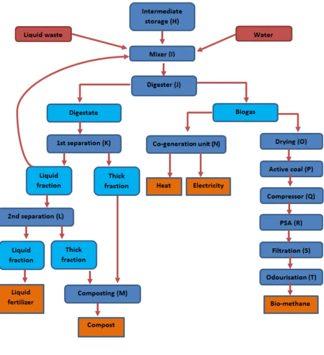
Digestate treatment
The raw digestate coming from the digester is processed in order to separate the l liquid from the thick fraction. This is done by using a 2-step separation system. Digestate first goes through 3 screw presses working in parallel. The second step consists in having 2 centrifuges take out as much as DM as possible from the liquid fraction. This liquid fraction is collected by farmers and applied on land as a fertilizer. The thick fraction will go through a complete composting process in a tunnel composting unit. The final compost is sold either in bulk or in small bags.
Biogas valorisation
On the Méthavalor site, there are 2 different ways of recovering biogas: either through a cogeneration unit or a biogas production one. These two plants are located on the site:
- Cogeneration
Part of the biogas is burned in a cogeneration unit to produce electricity and heat. The overall electricity production capacity is about 1.7 MWe. This electricity is primarily used to provide power to all the equipment on the site and the non-consumed electricity is directed to the grid. The heat produced by this cogeneration unit (about 2 MWth) is used to heat the digesters. It can also contribute to heating other applications either on the site or elsewhere. One Nm3 of biogas corresponds to about 2.4 kWe and 2.8 kWth when burnt in a cogeneration unit.
- Biomethanisation
The part of the biogas that is not burnt in the cogeneration unit will be “upgraded” to a level similar to the one of natural gas. In order to do this, CO2 and other impurities have to be
removed from the biogas. This purification is achieved in different steps: o Drying of the biogas (removal of water),
o Purification with active coal (removal of H2S),
o Compressing by increasing the pressure from 16 mbar to 10 bar, o 2-step Pressure Swing Adsorption (removal of CO2),
o Filter (final H2S removal).
The bio-methane that is produced has to be odourised so that people can smell the gas in case of accidental release into the air. On the Méthavalor site, this bio-methane is used as fuel. For each Nm3 of biogas that goes into the system, about 0.5 Nm3 of bio-methane is produced. The CO2 that is separated from the methane will be recycled in the digesters.
3.2.2 Unit operations
“Multiflux” sorting (A)
The “Multiflux” system will ensure the separation of the different types of coloured bags towards the right treatment system. It is a set of cameras and optical sensors combined with conveyor belts. There is always an additional “control step”, and in case 2 bags are accidentally misdirected, they will automatically be returned to the bulk storage.
Bag Opener (B)
All the organic waste coming from households is delivered in plastic bags which are taken to the ripper head on conveyor belts. The ripper head consists of ripper tines. The ripper head (rotor) holding the tines rotates in the opposite direction to the flow of material.
Plastic Removal (C)
Plastic (from the bags and similar objects) is removed by a wind-shifter.
Sieve (D)
As with the standard composting process, the particles that go into the system have to be small enough to ensure good interactions with the bacteria (both in the anaerobic treatment and in the composting unit.). Therefore, it is important to crush the parts that are too big. Normally, the size of the particles that go into the system should be less than 16 mm. All the particles that fall through the sieve go straight to the intermediate storage unit. The bigger parts go through the crusher. In this case, the sieving device is part of the conveyor belt.
Crusher (E)
Particles the size of which is superior to 16 mm will be crushed to a smaller size.
Ferro Detector (F)
Sieve (G)
With a mesh size of 12 to 16 mm, this will subdivide into smaller particles that can be stored in the intermediate storage unit for further processing and bigger ones that will be sent to the crusher again.
Intermediate storage (H)
The intermediate storage unit is a place in which all incoming organic flows (except the liquid ones) can be kept until further treatment. Given the fast decomposition of the material, it is essential (e.g. for the biogas production) for the retention time in this intermediate storage phase to be as low as possible.
Mixer (I)
At this point, the feed mix for the digesters is prepared, with a certain level of DM content and required inoculum. In this step, the mixing of incoming solid organic waste, incoming liquid organic waste and part of the thin fraction of the digestate is achieved. Water can be added to the mix if necessary to regulate the water content.
Digester (J)
Three dry digesters (type Kompogas) are used. These reactors are all plug-flow digesters that work non-stop, which makes it more convenient to manage both the manpower involved and the downstream located biogas-recovering equipment. The retention time of the organic material varies from 14 to 20 days. A low-speed agitator prevents the sedimentation of dense media materials and will take the material to the exit of the digester. The temperature inside the digesters is 50 – 55 °C, which corresponds to thermophilic conditions. The advantages of this higher temperature (compared to the one measured in mesophilic reactors) is that the conversion and digestion process occurs faster and that the material is free of spores, germs and micro-organisms after passing through the digester. On the other hand, the system is more sensitive to calamities and instabilities, which means that a closer monitoring of the system is required.
First separation (K)
A first division of the digestate is done with 3 screw presses. In this process, about 25 – 40 % of the DM are removed from the digestate. The thick fraction is sent to composting whereas the thin fraction will be further treated. It is important to note that, at this point of the process, there is a lot of odour production due to the loss of pressure and therefore a release of ammonia. This factor must be taken into account for the set-up of a similar plant, as this will require an adequate odour treatment system.
Second separation (L)
In the second separation step, the DM that remained in the liquid fraction coming from the screw presses will be further removed. As in this phase the DM-removal effectiveness needs to be higher, 2 parallel centrifuges have been installed. The removal potential of a centrifuge is normally about 75 % of the DM.
Composting (M)
The thick fraction coming from the screw presses and the centrifuges will be further composted. This is done in the same way as in the stages described before. The fully matured compost is sold in bulk or in bags.
Cogeneration unit (N)
Part of the biogas produced in the digester is transformed into heat and electricity in a cogeneration unit or in a combined heat and power plant (CHP unit). The total capacity of Méthavalor is 1.7 MWe. The heat produced is used to heat the digesters and other equipment or even buildings in the district. The heat produced by a CHP unit is available at different levels: the higher temperature level corresponds to the heat coming from the exhaust gases of the engine. The temperature of these exhaust gases at the outlet of the engine varies from 400 to 450 °C. About 20 – 25 % of the incoming energy is converted into heat. The lower temperature results from the heat coming from the cooling water from the engine. This heat is available at 55 or 90 °C. As this second type of heat is part of the cooling system, the cooling away of this heat is crucial for the smooth running of the CHP-engine. In case the heat is not consumed, it will be cooled away in air-coolers. About 20 – 25 % of the incoming energy is converted into this lower level heat. The power is used all over the plant – the remaining part is sent to the electricity grid. About 40-45 % of the energy generated by biogas is converted into electricity in the CHP-unit. Working with 2 CHP-engines (700 kWe and 1000 kWe) has the advantage that in case of maintenance of one of the devices, the other one can ensure enough energy production to keep the plant running.
Drying (O)
The biogas that is not burned in the CHP unit will be dried in order to remove the water it contains. This is done by cooling, leading to water condensation. After that, the condensed water is removed and the biogas is heated up again.
Active Coal (P)
Active coal is used to remove different kinds of impurities from biogas, among which H2S, siloxanes
Compressor (Q)
The pressure in the digesters is only 16 mbar, which is not sufficient to pass the complete processing unit and to obtain actual bio-methane. In this process, a pressure of about 10 bar is required. The rise (in pressure) from 16 mbar to 10 bar is obtained with the help of a biogas compressor.
Pressure Swing Adsorption (PSA) (R)
Pressure Swing Adsorption (PSA) is a dry method used to separate gases thanks to physical properties. The raw biogas is compressed and fed into an adsorption column. In this column, CO2
(carbon dioxide) is retained but methane (CH4) is not. If the column is saturated with CO2, the
pressure is released and the CO2 will be desorbed and led into an off-gas stream. In order to be able
to work in a continuous mode, it is important to work with multiple columns in parallel, which will alternately be closed and opened. The Méthavalor PSA-installation has a capacity of about 100 Nm3/h (input biogas flow).
Filtration (S)
Just before the biogas can be turned into engine fuel, a removal of all remaining impurities is necessary.
Odourisation (T)
Methane (CH4) as such is odourless and cannot be smelled by humans. Therefore, in order to
prevent unnoticed accidental releases, the bio-methane can be made detectable thanks to odourising agents.
3.2.3 Process scheme
Figure 3: Process scheme of Méthavalor (part 1).
Figure 4: Process scheme of Méthavalor (part 2).
Source: Sydeme-Méthavalor
3.2.4 Additional comments
The overall investment cost of the Méthavalor site is significant (about 40,000,000 €). Nevertheless, the operating company would like to extend the amount of digesters and to increase the capacity of the plant.
3.2.5 Useful contact(s) for further information
DLV Innovision (Belgium)
Email address: [email protected]
Sydeme-Méthavalor (France)
Email address: see website www.sydeme.fr/site/equip_methanisation1.php
3.3 Anaerobic digestion – Rainbarrow farm plant
3.3.1 General description
In 2012, the first commercial anaerobic digestion process generating biomethane connected to Grid Plant in England was started at Rainbarrow farm, in Cornwall. The anaerobic digester at Rainbarrow farm is fed with maize, grass, potato waste, whey and small amounts of food waste (chocolate and muesli) from local factories. The plant uses around 41,000 tons of maize grass and potato waste from local farmers as well as organic waste (e.g. chicken manure) from local farms and factories such as Dorset Cereals and the House of Dorchester Chocolate Factory (Lermen, 2013).
About 850 standard cubic metres/hour (Sm³/h) of biogas production can be achieved in the Rainbarrow plant. The gas produced (with approximately 53 % CH4) is shared between the energy
generator and the biogas upgrading system (gas grid injection). About 200 Sm³/h of biogas is used to fuel a 400 kW generator. Around 50 % of the generated energy is used on site to supply the installation and the rest is exported.
Up to 650 Sm³/h of biogas is led to the DMT Carborex® MS biogas upgrading plant, which cleans out the CO2 from the gas stream with a multistage system of membranes so as to reach a gas with a
content of 98.4 % CH4. Before entering the gas networks, biomethane gets into the Net Entry Facility
(NEF unit) where about 4 % propane is added to increase the biogas potential. At this stage, a specific gas odour is also added to the biomethane in order to match the quality of natural gas. The biomethane flow produced in Rainbarrow is around 400 Sm3/h which is enough to provide gas for 4,000 houses in winter. Moreover, the plant produces 8,000 tons/year of digestate which can be used as a fertiliser (Langerak, 2013).
3.3.2 Unit operations
The Rainbarrow multi-stage system makes use of highly selective membranes making it possible to optimize methane production (98% CH4), reduce propane addition and obtain pure CO2 (>99.5 %
pure). It is the only upgrading technology that also removes significant amounts of oxygen (up to 70 %) (Langerak, 2013).
After anaerobic digestion, the gas produced goes over to the upgrading plant where desulphurisation, removal of carbon dioxide and dehumidification are done (Dirkse, 2015).
Biogas compression
The incoming biogas is compressed to 8-10 bar. Since biogas usually contains small amounts of hydrogen sulphide, an oil-free compressor is needed. The compressed biogas is cooled with water obtained via a cooling system.
Removal of carbon dioxide and hydrogen sulphide
After the cooling phase, carbon dioxide and hydrogen sulphide are removed in a scrubber. The scrubber is designed for mass and heat transfer. The gases are absorbed together with the water at a low and constant temperature. The recirculation water is fed into the absorber at the top, while the biogas flows through the absorber in the opposite direction. They come into contact in the absorber and the carbon dioxide and hydrogen sulphide in the biogas are reduced. Carbon dioxide and hydrogen sulphide dissolve better than methane in water. Some methane will also be absorbed, but this can be recycled in the gas-freeing phases.
Gasses’ removal from circulation water
Used circulation water with dissolved gases goes through a flash vessel at a 2-bar pressure in order to reduce the methane losses. The water is partly degased and the gas from the flash tank is recirculated to the inlet of the upgrading plant. The gas inside the multi-stage membrane system separates CO2 from CH4 thanks to different permeation rates. The methane losses are controlled by
adjustments of the pressure in the flash tank.
The recirculation water out of the absorber is recycled by gas freeing in three steps.
- The recovered gas stream, with CO2, H2S and CH4 goes through the various pressure stages
for methane separation. In the meantime, the recirculation water coming from the absorber is recycled by freeing gas, while water pressure is reduced from 10 to 2-4 bar so as to release more gases. The gas recovered then goes through the pressure stages.
- The gas resulting from the lowest gas-freeing circuit with high concentration in CO2 either
goes through the pressure stages again or is used as industrial raw gas.
- The recirculation water coming from the methane recovery tower is sent into an air-stripping unit in order to release CO2 and H2S. In the air-stripping tower, the air coming from
outside is blown into a desorption tower where the recirculation water flows down the other way. Most of the CO2 and H2S is removed by stripping. The treated recirculation water
is pumped back to the absorber. The air coming from the air-stripping unit is sent to a Bio Trickling Filter (BTF) in order to reduce H2S contamination biologically. The BTF is a biological
plastic materials which act as biofilm carriers. The wastewater is fed into the filler at the top, whilst the air flows through the filter. Intensive mixing takes place in the filter and the contaminations in the air and water are reduced by the biofilm.
Biogas drying
An absorption dryer is installed behind the water absorption column to extract water from the upgraded biogas. The dryer is self-regenerating and consists of two columns containing a drying agent. The post-absorption upgraded biogas is dried and polished prior to delivery to the gas grid by vessels filled with a drying agent and activated carbon. The drying vessels self-regenerate by guiding approx. 5-10 % of the dried gas through the regenerating column.
Biogas purification
Before the dried gas is led into the column, it goes through a heat exchanger. The regeneration pressure is approximately 200 mbar, which means that the gas is quite fit to absorb the water in the drying agent. Granular Activated Carbon (GAC) vessels purify the upgraded biogas from H2S,
siloxanes and traces of HC. In order to optimize the process, CO2, CH4, H2O and H2S are measured
continuously. A programmable system controls the process according to the gas analyses results.
3.3.3 Process scheme
Figure 5: Process scheme of the DMT Carborex MS system.
Source: Lems R. and Dirkse E.H.M., (2010)
3.3.4 Useful contact(s) for further information
University of Leeds (United Kingdom)
Email addresses: [email protected], [email protected]
3.4 Anaerobic digestion – Nestlé’s Fawdon factory
3.4.1 General description
Nestlé’s Fawdon factory is one of the UK’s main confectionery production sites. The former Rowntree factory (Nestlé's second largest UK site) produces a range of confectionery brands. Fawdon factory set off an anaerobic digestion plant for the treatment of its wastewater. This plant is part of an initiative aiming at reducing the carbon footprint from the factory, and was started in August 2013 with a production of 300 kWe.
The anaerobic digestion plant treats liquid effluents, reject, confectionery and residual ingredients (mainly fed to pigs). By digesting these materials the plant is able to supply renewable energy to the factory, reducing disposal and power costs.
3.4.2 Unit operations
Nestlé’s liquid AD facility uses a wide range of techniques developed by Clearfleau (see Erreur !
Source du renvoi introuvable.), including several steps.
Feedstock supply
Two tanks balance variable flows. Solid residues are dissolved into the effluent before being fed into the reactor.
Anaerobic Reactor
A 1,500 m3 tank is fed with 275 m3/d of mixed feedstock. A separator returns degradable solids to the outside mixing digester.
Biogas Handling
The biogas generated in the digester and stored in the gas dome is cleaned prior to burning in the CHP located alongside the AD plant. At present, most AD plants produce renewable electricity from Combined Heat and Power (CHP) engines along with surplus heat. The electricity generated can be used on site (to replace bought-in power) or sold to the national power grid.
Process Control
In the middle of the plant, the control system includes simulation tools of all the key elements of the process linked to the site’s supervisory control and data acquisition system.
The project is beginning to lower the site’s CO2 emissions and helping to control energy costs. It is
part of an investment programme aiming at noticeably reducing its environmental footprint and enhancing sustainable production (Clearfleau, 2015; Gueterbock, 2014a; Gueterbock, 2014b; Clearfleau, 2013). The process scheme is shown in Figure 6.
3.4.3 Process scheme
Figure 6: Nestlé’s Fawdon Anaerobic Digestion Process.
Source: Gueterbock R., (2014 a)
3.4.4 Useful contact(s) for further information
University of Leeds (United Kingdom)
Email addresses: [email protected], [email protected]
3.5 Nutrient recovery from landfill leachate
Municipal landfill leachate results from the percolation of rainwater through solid waste and is seen as a wastewater type with one of the greatest environmental impacts because of high concentrations of ammonium, salts and organic matter. The conventional nitrification– denitrification is not very suitable for leachate treatment. Since the level of ammonia is high, high hydraulic residence times (and thus large reaction volumes) are required to reduce the toxicity coming from ammonia.
Recent investigations have shown that ammonium can be recovered from landfill leachate by struvite, magnesium ammonium phosphate (MAP) and precipitation (Oloibiri, 2013). The limitation of this way of recovering is that an external source of magnesium and phosphate is needed given the fact that landfill leachate is deficient in magnesium and phosphorus. Li and Zhao (2001) obtained a
reduction of the ammonium concentration in ammonium rich landfill leachate from 5,600 mg/L to 110 mg/L through struvite precipitation at a pH of 8.5 to 9.0. Results from Di Iaconi et al. (2010) showed that 95 % ammonium removal was achieved with a Mg:NH4:PO4 ratio of 2:1:1, at pH 9.
Similar studies confirmed that ammonium removal efficiencies of up to 90% can be achieved by struvite precipitation, involving addition of a magnesium and phosphorus source followed by pH adjustment (Kim et al., 2007). Struvite precipitation from landfill leachate is a technique under investigation and is not yet subject to full-scale implementation.
3.6 Phosphorus recovery from sewage sludge: generalities
3.6.1 Potentialities of sewage sludge in the United Kingdom: a case study
Phosphorus (P) is a nutrient indispensable to the growth of plants and the production of food. Modern agriculture uses mineral fertilizers which are derived from phosphate rock and need to be applied regularly to stimulate production. Since phosphate rocks are non-renewable, there is growing concern over a lack of phosphorus and subsequent sustainability of agriculture and food security (Cooper and Carliell-Marquet, 2013).
Cordell et al. (2009) reported that phosphate rock reserves are decreasing more and more in addition to being located in few countries (Morocco, China, USA and Western Sahara). The discharge of treated or untreated wastewater into bodies of water with high nitrogen and phosphorus concentrations has also caused eutrophication. Owing to this, it is necessary to recover P from waste streams and reuse it to various purposes.
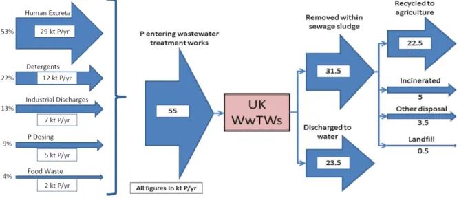
Since the UK relies on imported phosphorus, it is crucial to optimize its use and find out ways of recovering it most effectively. Figure 7 shows the imports and exports of phosphorus in the UK in 2009 (Cooper and Carliell-Marquet, 2013).
Figure 7: Global overview of UK imports and exports.
Source: Cooper J. & Carliell-Marquet C., (2013)
Around 60% of the P concentration in wastewaters comes from anthropogenic sources, since humans excrete most of the phosphorus they consume. Cooper and Carliell-Marquet (2013) determined that 48 % (55 kt P/y) of P net imports end up in the UK wastewater treatment plants (see Figure 8) whereas only 40.9 % of this wasted P are recovered for use in agriculture and 23.5 kt P/y are discharged into water bodies.
The dried solids resulting from the sewage sludge generated by the wastewater treatment contain P and N and are used in the UK agricultural process. These fertilisers have the advantage of releasing P more slowly than standard fertilizers and manures, which makes them more effective. Around 1 million of tons of dry solids are applied on land each year with the advantage of being inexpensive and more profitable for environment than incineration or landfill (Environment Agency, 2012). Another way to remove P and N is the chemical addition of FeCl3, a conventional and well-known
technology widely used in the UK (95 % of the wastewater treatment plants in the UK use this method). The main disadvantages are that it needs other processes, e.g. tertiary filtration. The use of FeCl3 also involves a mix with the sludge, which could prove expensive due to the addition of the
flocculating agent (cost estimated at £3.3 million/year for Wales). A last problem lies in the fact that P is considered a pollutant and not a resource (Environment Agency, 2012; Vale, 2013).
Figure 8: Phosphorus flows through UK wastewater treatment plants.
Source: Cooper J. & Carliell-Marquet C., (2013)
Phosphorus and Nitrogen recovery as struvite (magnesium ammonium phosphate) is a new trend in resources recovery from wastewater and involves the addition of MgCl2 at high pH for the
production of struvite salts. Struvite recovery is only practicable at high P concentrations and with small water volumes. Profitability is only possible with plants exceeding 75,000 population equivalents (one population equivalent corresponds to a five-day biochemical oxygen demand (BOD5) of 60 g per day) and P concentrations higher than 75 mg/L. To reach these levels, Biological
Nutrient Removal is advisable. The payback for some P recovery technologies can be as little as five years (Environment Agency, 2012). Phosphate removal and recovery will not just decrease the rising P concentration in UK rivers and pollution. It can also result in the production of struvite-type material which is rich in nutrients and can be sold as a fertiliser. It also contributes to lessening struvite-related damage to equipment. Besides, struvite has been classed as a product rather than waste by the UK regulations and consequently has a high market value (Ofwat, 2005).
3.6.2 Wastewater treatment plants as phosphorus sources
The existing phosphate recovery techniques from domestic wastewater can be applied at different points throughout the wastewater flow at the treatment plant (Schoumans et al., 2015; Desmidt et al., 2015). As shown in Figure 9, phosphate can be recovered from the liquid phase, from the sludge phase or from sewage sludge ashes. Since in wastewater treatment plants without phosphorus recovery, about 90-95% of the total phosphorus load is retained in the sewage sludge, the theoretical P recovery potential from sludge is higher than in the liquor phase (<50-60 %) (Cornel and Schaum, 2009). However, most current techniques aim at recovering phosphate from dewatering streams, since the low concentration of suspended solids makes it relatively easy to
Figure 9: Overview of the possible locations for phosphorus recovery from municipal wastewater (Ewert et al., 2014). 1 Direct agricultural utilization of dewatered sludge; 2a P recovery from anaerobically digested sludge before dewatering; 2b P recovery from anaerobically digested sludge liquor after dewatering; 3 P recovery from sludge ash after incineration.
Source: Ewert W. et al., (2014)
3.6.3 Global overview of the techniques applicable to the recovery of nutrients from
sewage sludge
P-recovery from the liquid phase
The phosphorus recovery methods from the liquid phase are implemented in a wastewater treatment plant with a biological phosphorus removal process, since the method requires the presence of free phosphates. The polyphosphate stored in the microorganisms after EBPR are partly released under anaerobic conditions, which causes an increase of the free phosphate content in the sludge systems, while if the phosphorus had been removed chemically with iron or aluminium salts, the phosphates would remain have remained bound to these metals after anaerobic treatment. The phosphorus rich water goes into a precipitation/crystallization tank where magnesium or calcium salts and, if necessary, seed crystals are added to remove phosphorus as calcium phosphate or magnesium ammonium phosphate (Cornel and Schaum, 2009), just like in struvite recovery from industrial wastewater.
P-recovery from the sludge phase
Phosphorus can be recovered from the sludge phase by a wet chemical or thermal technology. In a wet chemical treatment, phosphorus and all metals are extracted from the sludge. After being dissolved, the phosphate and metal ions are precipitated separately to obtain an uncontaminated phosphate fertilizer which can be used in agriculture as it is (Sartorius et al., 2012). This process, however, requires large amounts of chemicals and special acid-resistant equipment. Furthermore, many different residuals are produced and have to be disposed of at high costs (Sartorius et al., 2012). Struvite recovery from biologically treated sludge after anaerobic digestion has also been tested by Aquafin nv (Belgium). The technique is described in the Biorefine report ‘Recovery techniques from digestate and digestate derivatives’.
P-recovery from sewage sludge ashes
The phosphorus contained in sewage sludge ash can also be treated chemically or thermally. The wet chemical treatment involves re-dissolution by adding acid or base. In most cases, (heavy) metals are re-dissolved as well. After removal of the insoluble compounds, phosphates can be removed from the liquid stream through precipitation, ion exchange, nanofiltration, liquid-liquid extraction, etc. (Cornel and Schaum, 2009). Thermochemical treatment of sewage sludge ash removes heavy metals and improves the availability of phosphorus for plants. Ashes are exposed to chlorine salts, such as potassium chloride or magnesium chloride, and thermally treated. A large fraction of the heavy metals is turned into heavy metal chlorides which vaporize and are captured during gas treatment (Cornel and Schaum, 2009). A typical wet chemical process (Leachphos process) is described below.
3.7 Wet chemical treatment of sewage sludge ash
3.7.1 General description - Leachphos process
The Leachphos process as described by the P-REX project partners Adam et al. (2015) consists of two sequential steps: a leaching one and a precipitation one (see Figure 10). The sewage sludge ash is leached with dilute sulphuric acid in a stirred batch reactor. About 70-90 % of the total phosphorus content in the ash ends up in the leachate. The leaching process is followed by a solid/liquid separation (filtration) step using a vacuum belt filter or a filter press. The leached sewage sludge ash filter cake is withdrawn and must be disposed of. The phosphorus rich liquid stream is then pumped into a second stirred reactor in which the dissolved P is precipitated by dosing lime (CaO) or caustic soda (NaOH). If precipitation is conducted mainly with lime, phosphorus is present as calcium phosphate as well as aluminium phosphate. First results indicated that the P compounds are present in an amorphous form. Once the product has been purified, the liquid stream requires an additional treatment involving a pH increase (obtained by adding lime) and a sulphidic metal precipitation (obtained by dosing an organosulphide precipitation agent in a third reactor) followed by an additional solid/liquid separation step using a filter press. In this way, the metals in the wastewater
are removed almost completely. Afterwards, the pH is adjusted to 7 and the wastewater is discharged into a WWTP or a collecting water body.
3.7.2 Process scheme - Leachphos process
Figure 10: Flow chart of the Leachphos P recovery process.
Source: Adam C. et al., (2015)
3.7.3 General description - Mephrec process
The Mephrec process is described by the P-REX project partners Adam et al. (2015). The input for the process is dried sewage sludge, sewage sludge ash, coke and other additives for slag formation (such as limestone, cement, etc.). The process can treat dried sludge, ash or a mixture of sludge and ash. As shown in Figure 11, if dried sludge is used, the dewatered sewage sludge (25 % DM) is first dried to 80 % DM with a low-temperature dryer or screw dryer. The dried sewage sludge is then compacted to briquettes by means of a high pressure press. When sewage sludge ash is used as raw material, it is mixed with 10 % water in a mixer before briquetting. The briquettes, coke and other additives are weighed, mixed and added at the top of the Mephrec reactor by means of a bucket system. This implies that a quasi continuous supply of the reactor is guaranteed. In the reactor, the material is heated up to more than 1450 °C and moves from the top of the furnace down to the bottom where the melt metal and the melt slag are separated by the action of gravity. The liquid metal melt is tapped discontinuously. The slag melt continuously flows out of the siphon straight into a water basin. Thanks to the scraper in the water basin, a uniform grain size is obtained. The process step aiming at transforming the P-rich slag into a marketable fertilizer includes granulation
and ideally the addition of other nutrients to produce complex fertilizers. The produced iron alloy is enriched with phosphorus and can be used in the metal industry.
3.7.4 Process scheme - Mephrec process
Figure 11: Flow chart of the Mephrec P recovery process.
Source: Adam C. et al., (2015)
3.7.5 Useful contact(s) for further information
European Sustainable Phosphorus Platform (ESPP) Email addresses: [email protected]
P-REX project
3.8 Production of struvite from sewage sludge: PHOSPAQ® process
3.8.1 General description
Severn Trent Water have started the construction of a full-scale P and N recovery plant in Stoke Bardolph, Nottingham (UK) - using the PHOSPAQ®™ process - where they are planning to extract around 500 tons/year of phosphate contained in struvite from 2014 (Hadden, 2009; Vale, 2013). PHOSPAQ®™ is a cost-effective technology compared to e.g. dosing of iron salts. Moreover, the struvite produced is an excellent slow release fertilizer for N, P and Mg.
The PHOSPAQ®™ process removes biological degradable COD, phosphate (PO4
3-) and ammonium (NH4
+
) from wastewater. With oxygen, the COD is biologically converted into new biomass and CO2.
By adding magnesium oxide (MgO), phosphate and ammonium precipitate as struvite (MgNH4PO4.6H20 or MAP). The struvite granules are removed from the water phase, and are fit for
agricultural use (fertilizer) (Driessen, 2014). Severn Trent Water has come to an agreement with a fertilizer producer who will blend the struvite with nitrogen to produce fertilizer with the required nutrient balance (Hadden, 2009).
The treatments used in wastewater treatment plants usually involve:
- A preliminary treatment - so as to remove grit and gravel as well as screen large solids, - A primary treatment - to settle larger suspended matter (mainly organic),
- A secondary treatment - to biologically break down and reduce residual organic matter, - A tertiary treatment - to get rid of different pollutants using different treatment processes, - A sludge treatment – to treat the sludge by anaerobic digestion for the production of
methane and bioenergy.
PHOSPAQ® Process
Severn Trent Water’s Stoke Bardolph STW, Nottingham, UK use PHOSPAQ®, UASB+ and ANAMMOX® techniques in a combined process. The sludge dewatering liquors are first treated in a phosphate removal reactor (PHOSPAQ®™), while the sludge stream is treated in a UASB+ reactor for biogas production. Both streams are then combined and treated in a nitrogen removal reactor (ANAMMOX®) (Durose and Jeffcoat, 2014).
The PHOSPAQ® process is used to recover phosphate from effluents such as struvite. Phosphate is becoming limited and PHOSPAQ® is considering a technology less expensive than the one consisting in dosing iron salts. Furthermore, the struvite obtained is an excellent fertilizer containing N, P and Mg (Durose and Jeffcoat, 2014).
In the BIOPAQ® UASB bioreactor, organic compounds are transformed into biogas by bacteria in anaerobic conditions. The main advantages of this process are the production of power-generating biogas, a high effectiveness in COD removal, a small reactor height and a closed system with no odour emissions. It is anticipated that BIOPAQ® UASB reactor will produce approximately 3 MW hour/day, which is enough to power 200 houses (Durose and Jeffcoat, 2014).
After treatment of the sludge dewatering liquor by the PHOSPAQ® reactor, the effluent is combined with a nutrient-rich trade liquor and subsequently treated by an ANAMMOX® reactor for the removal of nitrogen (Driessen, 2014). The process offers several advantages such as low energy use, non-clogging of pipes by struvite because of P removal and an operational cost benefit of £165K per year when compared with a conventional aerobic wastewater treatment (Wild, 2014).
The PHOSPAQ®™ reactor works with a continuous aeration and stirring system with magnesium addition for the formation of struvite. The chemical reaction can be described as follows (Equation
1): Mg2+ +NH4 + + HPO4 + 6H2O MgNH4PO4.6H2O + H +
Eq.1: Formation of Magnesium ammonium phosphate (MAP): NH4-struvite
For the stimulation of struvite crystallization, pH must be raised to 8/8.5 by stripping the carbon dioxide (CO2) (≈ 90 Nm³/h; 60 kWh/d) and adding magnesium oxide (MgO, 125 kg MgO/d) in a 50 m
3
reactor (7 m in height, 3 m in diameter). The addition of MgO instead of MgCl2 is preferred because
it is more economical and helps to raise the pH, which also eliminates the need for additional NaOH (Wild, 2014). PHOSPAQ® reactor has shown recovery percentages of 95 % of phosphate and around 22 % of ammonia in some wastewater treatment plants (Remy, 2014).
Furthermore, Severn Trent Water uses the ANAMMOX® process for the removal of ammonia and nitrites as N2 gas to meet the N discharge limitations (Driessen, 2009). After the removal of nitrogen
and phosphates by struvite, the one-step ANAMMOX® reactor converts ammonium and nitrites by associating nitritation and the ANAMMOX® process linked bacteria without requiring an external carbon supply and a low oxygen consumption as shown in the equation below (Equation 2):
2NH4 + + 1.7O2 1.14NO2- + 0.86NH4 + 0.88N2 + 0.24NO3 + 2H+ + biomass
Eq.2: Removal of ammonia and nitrite using the ANNAMOX® process
A red granular biomass is generated owing to specific enzymes. The reactor is continuously aerated and can be controlled by measuring nitrite and ammonium.
The ANAMMOX® process is appropriate for different types of liquors, such as sewage sludge digestion liquors, dewatering liquors from Thermal Hydrolysis Plants and anaerobic effluents from industry (Driessen and Reitsma, 2014). An ANAMMOX® reactor is around 55 m3, 6 m in height, 3.5 m in diameter, with a load of 2.2 kg N/m3·d, a fine bubble aeration (≈180 Nm³/h, 100 kWh/d) and 96 % N removal (Remy, 2014).
According to Remy (2014), the combination of PHOSPAQ® and ANAMMOX® treatments can achieve a struvite production of 212 tons (expressed in DM) per year with 95 % phosphate recovery (73 kg/d) and 75 % ammonium removal rates.
3.8.2 Unit operations
1) Conventional wastewater treatment process Wastewater collection (1)
Wastewater goes down into a pipe which takes it to a larger sewer pipe under the road. The sewer joins the sewage network which then takes the wastewater to a sewage treatment plant.
Screening (2)
The first stage of wastewater treatment is the removal of large objects such as face wipes, sanitary items, rocks, plastics, etc. that may block or damage equipment, or be unsightly if allowed back into the catchment water surface. The liquid flows through a number of sieves which remove these materials.
Primary treatment (3)
After removal of big debris, the wastewater is sent into large settlement tanks, which causes the solids (sludge) to settle on the bottom of the tank. These tanks have a circular shape and large arms (scrapers) which move slowly around the tank to push the sludge to the bottom. The sludge is pumped away for further treatment. The effluent overflows out of the tank and is taken to the next stage of the treatment process.
Secondary treatment (4)
The effluent from the primary sedimentation is sent to rectangular tanks called ‘aeration lanes’. The secondary treatment is an aerobic treatment (air is pumped to maintain a concentration of oxygen in the reactor) where a consortium of bacteria break down the organic materials in the water. The products from the aerobic sewage treatment are carbon dioxide, water and nitrogen gas. The effluent flows out of the tanks to be directed to further settling tanks.
Secondary sedimentation (5)
The treated wastewater is taken to a final settlement tank, where the bacteria sink to the bottom. The sludge on the bottom of the tank is recycled back to the aerobic treatment stage to keep an optimal concentration in bacteria and the rest is sent to sludge treatment. The clean water overflows out of the settlement tank for disposal, although additional treatment is sometimes needed before disposal.
Polishing (6)
To meet some standards relating to specific pollutants and the removal of small particles, cleaned water is often filtered through shallow gravel or sand beds as a final step.
Treated water discharge (7)
After the whole treatment, wastewater is clean and sent back to local rivers and streams. The quality of the treated wastewater depends on the legal constraints of the country concerned.
Sludge thermal treatment (8)
The sludge collected from the primary and secondary sedimentation tanks is then treated by a hydrothermal process to obtain a high degree of hydrolysis of carbohydrates, proteins, lipids and bacterial cell wall biomass. The hydrothermal process is energy-effective, reaches high digestion levels and raises biogas production. Sewage sludge treated by hydrothermal process (165 °C, 10 bar, 30 min) has been used amply as feedstock for methane production with good yields and productivity in many countries, including the UK, the USA, Norway, Germany, etc. (Abu-Orf et al., 2011; Kepp et al., 2000; Panter, 2001; Ross et al., 2010). Thermal hydrolysis increases biogas yield, destroys salmonella and 99.9999 % of the pathogens. These bio-solids are approved by Water UK and the British Retail Consortium for use as a soil conditioner for all types of crops. The biogas produced by the anaerobic digestion process can be used as fuel in a combined heat and power (CHP) plant or cleaned and injected straight into the national gas grid (Tillier, 2013).
Anaerobic Digestion (AD) (9)
After going through the hydrothermal process, the waste activated sludge is sent to bioreactors for anaerobic digestion. AD is a natural process in which a consortium of microorganisms breaks down organic matter in anaerobic conditions for the production of biogas (CO2 and CH4) and digestate (a
nitrogen-rich fertilizer). Biogas is normally used to power engines for CHP, burnt to produce heat, or can be cleaned and used as natural gas or as a vehicle fuel. In addition to that,digestate can be used as a fertilizer or soil conditioner. AD is no new technology and has been widely used in the UK for the treatment of sewage sludge for over 100 years (DEFRA, 2011). Around 660,000 dry tons of separated, treated solids return to environment as sludge every year. Thames Water uses the sludge for anaerobic digestion where bacteria grow at 35 oC for at least 12 days, turning organic matter into gas which is burnt in engines.
2) PHOSPAQ® Process Stirring and Aeration (1)
The water rejected from the anaerobic digester is sent to the PHOSPAQ® reactor for the sake of stirring and aerating with CO2. CO2 bubbling increases the pH to about 8.0-8.5.
Magnesium addition (2)
When pH is about 8, magnesium salts are added to stimulate the controlled formation of struvite, as shown in the previous reaction. Due to high pH, struvite crystallization is facilitated.