HAL Id: hal-01202656
https://hal.archives-ouvertes.fr/hal-01202656
Submitted on 27 Jan 2018HAL is a multi-disciplinary open access
archive for the deposit and dissemination of sci-entific research documents, whether they are pub-lished or not. The documents may come from
L’archive ouverte pluridisciplinaire HAL, est destinée au dépôt et à la diffusion de documents scientifiques de niveau recherche, publiés ou non, émanant des établissements d’enseignement et de
Reducing the Spectral Emissions of PFC Converters by
Anticontrol of Chaos
Marcelle Mehry, Cristina Morel, Eric Chauveau, Mohamed Machmoum
To cite this version:
Marcelle Mehry, Cristina Morel, Eric Chauveau, Mohamed Machmoum. Reducing the Spectral Emis-sions of PFC Converters by Anticontrol of Chaos. International Journal of Power Electronics and Drive Systems, IAES 2013, 3, pp.9-18. �hal-01202656�
Reducing the Spectral Emissions of PFC Converters by
Anticontrol of Chaos
Marcelle Merhy1,2, Cristina Morel1, Eric Chauveau1, Mohamed Machmoum2 1ESEO Group, Graduate School of Engineering, Angers, 49009, France 2IREENA, 37 Boulevard de l’Université BP 406, 44602 Saint-Nazaire, France
Abstract: Switch-mode power supplies usually emit electromagnetic interferences at the switching
frequency and its multiple harmonics. We propose a feedback control method improving switch-mode power supplies electromagnetic compatibility (spectral peaks compliance). Inducing chaos in these systems has recently been suggested as a means of reducing these spectral emissions. Indeed, the application of the classical method of chaos anticontrol to these systems leads the output voltage to have an excessive ripple or an undesirable spectrum, whereas these problems are solved with ours. We propose here a converter, able at the same time to achieve low spectral emission and to maintain a small ripple. The design of this controller is based on the property that chaotified nonlinear systems present many independent chaotic attractors of small dimensions. To confirm the efficiency of this method, a comparison with the anticontrol method is included, together with a numerical example clearly showing the effect of this control.
Keywords: PFC converter, Output voltage ripple, Anticontrol of chaos, Independent chaotic attractors,
Power spectrum
1. INTRODUCTION
Power electronic circuits are prone to various types of nonlinear phenomena, like bifurcation and chaos. Among different types of power electronic circuits [1]-[3], dc–dc converters are most widely explored. Bifurcation and chaos, a phenomenon which can naturally occur in switch-mode power supplies has been reported in voltage-mode controlled Buck converters and Boost converters operating in continuous or discontinuous conduction mode. All the reported literatures [2] [3] assume that the input of a dc–dc converter is a regulated dc power supply: this usually is not the case in reality. The converters are mostly fed from a rectified and filtered source; in this case, this dc voltage will contain ripple (the peak to peak input voltage).
Switch-mode power supplies generate electromagnetic interference at the switching frequency and its multiple harmonics. Interference emission creates significant electromagnetic compatibility (EMC) difficulties, especially when high currents or high voltages are switched rapidly. The reduction of spectral
are to use a time-delay feedback perturbation on a system parameter or to employ an exogenous time-delay state-feedback input.
The anticontrol method designs a nonlinear feedback controller with an arbitrarily small amplitude [9] [10], thus obtaining chaotic dynamics in the controlled system. The application of this method [6] [10] to switch-mode power supplies reduces the output voltage spectral emissions, but increases the overall magnitude of the output voltage.
After the study of the photovoltaic systems [22][23],the purpose of this article is to introduce a nonlinear feedback controller that maintains a small ripple in the output voltage and also achieves a low spectral emission. Its design is based upon a property exhibited in [19]-[21]: a chaotified nonlinear system presents many small independent chaotic attractors. The initial nonlinear system is chaotified using a simple sine function of the system state, as in [7], but with large amplitude. The feasibility and usefulness of this new and simple method is shown here with a numerical example, in a power factor correction (PFC) Boost Buck converter [24].
2. ANTICONTROL OF CHAOS
Consider aN-dimensional nonlinear system in the following general form
N j i j i i N j i i i N i i i N N j i j i i N j i j i i N i i i N j i j i i N j i j i ij N i i i x x s x r x q x x x o x x n x m x x x c x x b x a x 1 1 2 1 1 1 1 1 2 1 1 1 2 1 1 2 1 1 1 1 (1)whereai, bij, cij, mi, nij, oij, qi, rij, sij for i,j1,N are real parameters and xi for i = 1,N are the state variables. In order to generate a chaotic behavior in this system, let us introduce a piecewise-binary characteristic of the feedback controller, defined analytically as follows:
) ( ) ( , 1 ) ( ) ( , 0 t v t v t v t v c r c r (2)
where vr(t) is a periodic function and vc(t)the anticontrol state feedback. We propose to use the anticontrol with a piecewise-binary controller, hereafter called anticontrol switching piecewise-binary controller. The application of the anticontrol of chaos uses a nonlinear state feedback:
x(t)
. sin c ) t ( vc 1 (3)We consider now a fast dynamics variation of given by the anticontrol switching piecewise-binary controller of (2). As Figure 1 presents, for each attractor starting from different initial conditions, the dynamical state space trajectory remains around the equilibrium point.
Figure 1. Example of chaotic attractors.
The application of the piecewise-binary controller in continuous-time nonchaotic systems (1), outlines two very important properties. The first one is the generation of several independent periodic attractors. Recently, [21] demonstrated that the equidistant repartition of these attractors is in a precise zone (a controllable state space area) of a precise curve, which depends of the sine anticontrol feedback vc(t) frequency. Then, the state space domains where the attractors are generated from different initial conditions were determined. Also, a mathematical formula giving the maximal attractors number in function of the controller piecewise-constant values has been deduced [21]. In this paper, we are interested by the second property: the size of the attractors. The design of this controller is based up on the property that chaotified nonlinear systems present many independent chaotic attractors of small dimensions: this is used to improve the EMC of PFC Boost-Buck converter by reducing spectral peaks.
3. THE BUCK CONVERTER
Figure 2 shows the diagram of a Buck converter that uses a pulse width modulated voltage loop [2]. The circuit has two states determined by the position of the switch S. When S is closed, the input voltage Vin provides energy to the load R1 as well as to the inductor L1. When S is open, the inductor current i, who flows through diode D, transfers some of its stored energy to the load R1. The anticontrol switching piecewise-binary control law together with a typically proportional (the constant a) controller
()
sin
( )
)
(t a v t V c v t
vc ref (4)
is applied to the inverting input of the comparator A1. The non-inverting input is connected to an independent voltage ramp generator vr(t):
. T T mod t V V V ) t ( vr L U L (5)The Buck converter is a second-order system since it has inductive and capacitive energy storage elements. The voltage v of the capacitor C and the inductance current i are chosen as state variables. This classical converter has been studied for many years, notably in [2], [3] assuming a regulated dc power supply input voltage. But usually, such is not the case in reality. The dc input voltage Vin(t) = E + e·sin(2ft) will contain a ripple.
Figure 2. Buck converter with feedback anticontrol of chaos: L1 = 10 mH, C1 = 33 F, R1 = 1.5 ,
Vref = 24 V, a = 8, VU = 8.2 V, VL = 3.8 V, E = 240 V, e = 16 V, f = 50 Hz and T = 20 s.
The model of the converter can be written as:
. ) t ( L ) ft sin( e E ) t ( v L dt di ) t ( v RC ) t ( i C dt dv 2 1 1 1 (6)
Varying the values of parameters c andω, Figure 3 presents the maximum of the output voltage ripple in function of the anticontrol feedback parameters. This ripple falls to very small values for high c and amplitudes. The low ripple area can then be identified. Every point (c, ω) inside of this area is characterized by a small output voltage ripple and several chaotic attractors, dependent of the initial conditions (using (4) with large amplitude of c). Figure 3 presents another area characterized by an important output voltage ripple and a unique attractor, independent of the initial conditions. We begin with a series of typical waveforms (the output voltage, the power spectrum and phase portrait of the state equation of the Buck converter Figure 4 – Figure 15) which have been obtained from computer simulations.
Figure 3. The maximum of the output voltage ripple in function of the anticontrol feedback parametersc and ω.
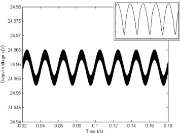
The output voltage of this circuit, when the converter is governed by the control law of Eq. (4) with c=0 is shown in Figure 4: it is periodic with a low frequency of 50Hz (the frequency of the input voltage Vin). In this case we obtained a 10 mV ripple. A close-up view of the output voltage v(t) shows the high switching frequency of 50kHz.
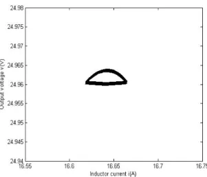
Figure 5 represents the power spectrum of the output voltage v(t). The spectrum has a peak at the switching frequency, with a magnitude of -80dB/Hz. Figure 6 shows the phase portrait which corresponds to the periodic orbit. For electromagnetic compatibility compliance reasons, let us try to reduce the peak value of the spectrum while maintaining a small ripple.
Figure 4. The periodic output voltage v(t) of the Buck converter with the control law of Eq. (4) forc=0.
Figure 6. Phase portrait of the state equation of the Buck converter for c=0.
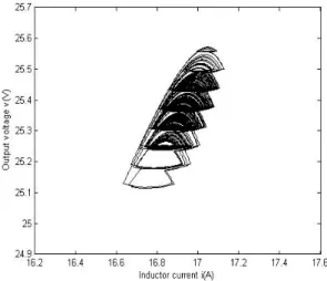
Let us suppose that c has a small amplitude as in [8] [10]. Unfortunately, the time-domain performance is worsened because the output voltage ripple has increased to 500 mV as in Figure 7. The small amplitude of the parameter c leads to the conclusion that, the efficiency of the DC-DC converter reduces, as in [11]. Figure 8 presents the power spectrum of the output voltage v(t), for c = 5V and ω = 100 rad/V: the maximum of this spectrum is equal -64dB/Hz. The output voltage v(t) has a large variation attracted into an chaotic attractor as in Figure 9. Applying the anticontrol chaos (with small amplitude of c) to switch-mode power supplies aggravates the time-domain performance, but also deteriorates the frequency-domain performance.
Figure 7. The output voltage v(t) of the Buck converter with the control law of Eq. (4) for c=5V and ω =100 rad/V.
Figure 8. Power spectrum of the output voltage v(t) with the control law of Eq. (4) for c=5V and ω =100 rad/V.
Figure 9. Chaotic attractor phase portrait of the state equation of the Buck converter for c = 5V and ω = 100 rad/V.
We are interested in a large variation of the parameter c. Let us show that the c amplitude of the anticontrol of chaos state feedback vc(t) has the key role to maintain a small ripple in the output and is able at the same time to achieve low spectral emission. Increasing the c amplitude decreases the output voltage ripple (see the 0.5 mV of Figure 10) and the maximum of the power spectrum decreases also (see the -120 dB/Hz of Figure 11). The reduction of the maximum of the power spectrum of v(t) can be achieved by increasing also the angular amplitude . The dimension of the chaotic attractor decreases (Figure 12).
Figure 10. The output voltage v(t) of the Buck converter with the control law of Eq. (4) for c=150V and ω =500 rad/V.
Figure 11. Power spectrum of the output voltage v(t) with the control law of Eq. (4) for c = 150V and ω =500 rad/V.
Figure 12. Chaotic attractor phase portrait of the state equation of the Buck converter for c = 150V and ω =500 rad/V.
Table 1 summarizes the ripple and the power spectrum of the output voltage v(t), using different values of the parameter c. It shows that the power spectrum amplitude of the converter governed by a control law vc(t) with small amplitude of c increases the power contained in the peaks harmonics of the output voltage and leads to a large ripple. The large values of c and we propose ensure a good ripple and cause a spectacular decrease of the power spectrum amplitude.
Table 1. The performance of the Buck converter with diffeternt values of c and .
c (V) (rad/V) Ripple (mV) Maximum of power spectrum (dB/Hz) 0 0 10 -80 5 100 500 -64 150 500 0.5 -120
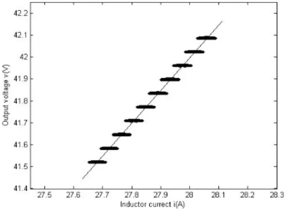
Figure 13 presents several independent chaotic attractors reached from different initial conditions for small variations of c. In order to avoid the superposition of the attractors in a graphical state space representation, we represent them according to v(t) and c in Figure 13. Let us study their repartition in the state space in function of c. For small c, the Buck converter is characterized by a unique attractor. For a large c, the system presents several independent chaotic attractors, reached from many different initial conditions, as in Figure 14. Without any change of the Buck converter parameters, all the chaotic attractors are situated on the same curve depending on R. In order to avoid different regimes of operation (as Figure 14) and to make the Buck system converge to one attractor of interest (with the output voltage around Vref), starting
from different initial conditions, the anticontrol switching piecewise-binary control law is used together with a classical PID controller. The simulation results are presented in Figure 15.
Figure 15. Independent chaotic attractors of the Buck using anticontrol switching piecewise-binary control law together with a classical PID controller.
4. TWO-STAGE PFC POWER SUPPLIES
Power-factor-correction power supplies are required to provide high input power factor [12] and tight output voltage regulation. The objective of an active PFC is to make the input of the power supply look like a simple resistor: the PFC preregulator does this by programming the input current in response to the input voltage. Recently some nonlinear behaviors in the PFC boost converter have been reported [13] [14] [25] as fast-scale bifurcation [15-17] and slow-scale bifurcation [17] [18]. The above bifurcations are both observed at the switching frequency. The PFC converter is a more complicated system and an interesting case, because the input voltage is periodic with low frequency and the switching signal is periodic with high frequency.
The usual configuration takes a two-stage PFC dc/dc cascade structure, consisting of a PFC preregulator and a dc/dc converter. Both are designed to operate in continuous conducting mode. In this paper, we study by computer simulations the interaction between the PFC stage and the dc/dc Buck converter stage on the design of the anticontrol of chaos state feedback to achieve low spectral emission.
The boost converter circuit schematic used in the PFC is shown in Figure 16. The component values of the complete Simulink of the two-stage PFC power supply, with both the boost PFC preregulator and the Buck output regulator is presented in Appendix A. The feedback of the PFC Boost stage is necessary to program the input current to follow the input voltage waveform and must control both the input current and the PFC output voltage. To achieve near unity power factor the demanded current is in phase with the demanded voltage. The demanded voltage VPFCref is compared to the capacitor voltage voutboost and the error signal is filtered using a typical first-order low-pass filter (with the time constant Tv) to remove any unwanted noise. The filtered error is fed to a conventional PI controller (P2 and P2/Tc the constants) and the output is multiplied by the rectified input voltage times by a proportionality constant P1.
The output of the multiplier is the current programming signal that has the shape of the input voltage. The PFC output voltage is controlled by changing the peak current mode control amplitude (as in Figure 17) of the current programming signal. The boost PFC preregulator typically gives a high output voltage (as in Figure 18) which is greater than the highest expected peak input voltage and provides very crude regulation. This way, a Buck converter is needed to step this voltage down to a useable level and to provide tight output regulation. In this part, the same Buck converter is used, with the same parameters as in the previous part.
The results concerning themaximum of the output voltage ripple in function of the anticontrol of chaos feedback parameters cand ωfor the complete two-stage PFC power supply are presented in Figure 19. This ripple falls to very small values for a wide domain of low ω angular frequencies and for high c amplitudes. The low ripple area can then be identified for high c amplitudes. Every point (c and ω) inside of this area is characterized by a small output voltage ripple and several chaotic attractors, dependent of the initial conditions (with large amplitude of c). Figure 19 also presents a grey area: every point inside of this area is characterized by an important output voltage ripple and a unique attractor, independent of the initial conditions.
Figure 16. The PFC Buck-Boost power supply converter.
Figure 19. The maximum of the output voltage ripple v(t) in function of the anticontrol feedback parametersc and ω, of the complete two-stage PFC power supply.
For few particular values (the same choice of parameters as for the Buck converter) of the anticontrol feedback parametersc and ω of the complete two-stage PFC power supply, we present the output voltage, the power spectrum and phase portrait (Figure 20 – Figure 28).
Figure 20 shows the waveform of the output voltage v(t) of the complete two-stage PFC power supply with the control law of Eq. (4) forc = 0, where it can be see a ripple of smaller than 10 mV. The power spectrum of v(t) is mainly composed of the fundamental frequency (a -90 dB/Hz sharp peak at 50 kHz) and its harmonics, as presented in Figure 21. Figure 22 shows the phase portrait of (i, v).
Figure 23 also presents that the parameter c has a strong influence on the output voltage ripple. For example, while c changes from 0 to 5 V, there is an increase of the ripple up to 500 mV. The power spectrum of v(t) of the complete two-stage PFC power supply is shown in Figure 24. It is known that the amplitude at the clock frequency (50 kHz) is the main source of EMI due to power converters. We observe a 5 dB/Hz increase of this amplitude for the output voltage v(t). Consequently, Figure 25 presents an increasing phase portrait dimension of the chaotic attractor.
If c amplitude of the anticontrol of chaos state feedback vc(t) is increase even more, then the maximum of the power spectrum decreases, as shown in Figure 27. The no periodicity of the power spectrum of v(t) indicates the presence of chaos. The whole frequency range is continuously spanned. The dimension of the chaotic attractor (Figure 28) in the phase portrait also decreases.
We report our measurements in Table II and summarize the ripple and power spectrum of v(t), using the same particular values of the anticontrol feedback parametersc and ω of the complete two-stage PFC power supply as for the Buck converter. The nonlinear feedback controller vc(t) proposed here with large amplitudes
of c maintains a small ripple in the output and is able at the same time to achieve low spectral emissions. This demonstrates that anticontrol of chaos improves power supply EMC.
Similar to the analysis of the Buck converter, the anticontrol of chaos state feedback vc(t) still achieves low spectral emission and maintains a small ripple even if the this one is used as load for the PFC Boost converter. In other words, we may conjecture from the above results that anticontrol switching piecewise-binary control law vc(t) presents a typical characteristic: low spectral emissions.
Table 2. The performance of the PFC Buck-Boost converter with diffeternt values of c and .
c (V) (rad/V) Ripple (mV) Maximum of power spectrum (dB/Hz) 0 0 10 -90 5 100 550 -85 150 500 0.5 -170
Figure 20. The output voltage v(t) of the complete two-stage PFC power supply with the control law of Eq. (4) forc=0.
Figure 21. Power spectrum of the output voltage v(t) of the complete two-stage PFC power supply with the control law of Eq. (4) forc=0.
Figure 23. The output voltage v(t) of the complete two-stage PFC power supply with the control law of Eq. (4) for c = 5V and ω =100 rad/V.
Figure 24. Power spectrum of the output voltage v(t) of the complete two-stage PFC power supply with the control law of Eq. (4) for c=5V and ω =100 rad/V.
Figure 25. Phase portrait of chaotic attractor of the complete two-stage PFC power supply c = 5 V and ω =100 rad/V.
Figure 26. The output voltage v(t) of the complete two-stage PFC power supply with the control law of Eq. (4) for c = 150 V and ω = 500 rad/V.
Figure 27. Power spectrum of the output voltage v(t) of the complete two-stage PFC power supply with the control law of Eq. (4) for c = 150 V and ω = 500 rad/V.
Figure 29. The PFC Simulink schematic: Vac = 154 V, Fac = 50 Hz, L2 = 2 mH, C2 = 470 F, Tv = 4 ms, Tc = 1/70 s, P2 = 1/60, P1 = 0.08, VPFCref = 240V, T = 20 s.
5. CONCLUSION
We propose a feedback control to the complete two-stage PFC power supply in order to demonstrate that chaos improves power supplies EMC without any other feedback. To confirm the efficiency of this new method, a comparison with the anticontrol method is included. Indeed, the application of the classical method of chaos anticontrol to these systems leads the output voltage to have an exaggerated output voltage ripple and an undesirable spectrum, whereas these problems are solved with ours. The new controller proposed in this paper improves the time-domain (ripple) performance and the frequency-domain (spectral) performance.
REFERENCES
[1] DC Hamill, JHB Deane and DJ Jefferies. “Modeling of Chaotic DC-DC Converters by Iterated Nonlinear Mappings”. IEEE Transactions on Circuits and Systems-: Fundamental Theory and Application. vol.7 (1992), pp.25, 1992.
[2] E Fossas and G Olivar. “Study of Chaos in the Buck Converter”. IEEE Transactions on Circuits and Systems-I:
Fundamental Theory and Application. vol.43, pp.13, 1996.
[3] C Tse. Complex Behavior of Switching Power Converters; New York, CRC Press 2003.
[4] FL Lin and DY Chen. “Reduction of Power Supply EMI Emission by Switching Frequency Modulation”. IEEE
Transactions on Power Electronics. vol. 9, pp. 132, 1994.
[5] JHB Deane, P Ashwin, DC Hamill and DJ Jefferies. “Calculation of the Periodic Spectral Components in a Chaotic DC-DC Converter”. IEEE Transactions on Circuits and Systems-I: Fundamental Theory and Application. vol. 46, pp. 1313, 1999.
[6] O Woywode, H Guldner, AL Baranovski and W Schwarz. “Bifurcation and Statistical Analysis of DC-DC Converters”. IEEE Transactions on Circuits and Systems-I: Fundamental Theory and Application. vol. 50, pp. 1072, 2003.
[7] XF Wang and G Chen and KF Man. “Making a Continuous-Time Minimum-Phase System Chaotic by using Time-Delay Feedback”. IEEE Transactions on Circuits and Systems-I: Fundamental Theory and Application. vol. 48, pp. 641, 2001.
[10] XF Wang, G Chen and X Yu. “Anticontrol of chaos in continuous-time systems via time-delay feedback”. Chaos. vol.10, pp. 771, 2000.
[11] G Chen and D Lai. “Making a dynamical system chaotic: feedback control of Lyapunov exponents for discrete-time dynamical systems”. IEEE Transactions on Circuits and Systems –I: Fundamental Theory and Application. vol.44, pp.250, 1997.
[12] M Orabi, T Ninomiya. “Nonlinear dynamics of power factor correction converter”. IEEE Trans. Industrial
Electronics. vol. 50, pp. 1116, 2003.
[13] O Dranga, CK Tse, HHC Iu, and I Nagy. “Bifurcation behavior of a power–factor-correction boost converter”. Int.
Journal of Bifurcation and Chaos. vol. 13, pp. 3107, 2003.
[14] A Pandey, DP Kothari, AK Mukerjee and B Singh. “Modeling and simulation of power factor corrected AC-DC converters”. Int. J. Electrical Engineering Education. vol. 41, pp. 705, 2004.
[15] CK Tse. “Fast-scale instability of single stage power factor correction supplies”. IEEE Transactions on Circuits and
Systems-I: Fundamental Theory and Application. vol. 53, pp. 204, 2006.
[16] HC Herbert, Z Yufei, and CK Tse. “Fast scale instability in a pfc boost converter under average current mode control”. Int. J. Circuit Theory Application. vol. 31, pp. 611, 2003.
[17] D Dai, M Li, X Ma. “Slow-scale and fast-scale instability in voltage mode controlled full-bridge inverter”. IEEE
Transactions on Circuits and Systems-I: Fundamental Theory and Application. vol. 27, pp. 811, 2008.
[18] D Dai, S Li, X Ma, CK Tse. “Slow-scale instability of single stage power-factor-correction power supplies”. IEEE
Trans. Circuits Syst. I: Fundamental Theory and Application. vol. 54, pp. 1724, 2005.
[19] C Morel, M Bourcerie and F Chapeau-Blondeau. “Generating independent chaotic attractors by chaos anticontrol in nonlinear circuits”. Chaos, Solitons and Fractals. vol. 26, pp. 541, 2005.
[20] C Morel, R Vlad and JY Morel. “Anticontrol of Chaos Reduces Spectral Emissions”. Journal of Computational and
Nonlinear Dynamics. vol. 3, pp. 041009, 2008.
[21] C Morel, R Vlad and E Chauveau. “A new technique to generate independent periodic attractors in the state space of nonlinear dynamic systems”. Nonlinear Dynamics. vol. 59, pp. 45, 2009.
[22] D Petreus, T Patarau, S Dărăban, C Morel, B Morley. “A Novel Maximum Power Point Tracker Based on Analog and Digital Control Loops”. Solar Energy. vol. 85, pp.588-600, 2011.
[23] C Morel, D Petreus and A Rusu. “Application of the Filippov Method for the Stability Analysis of a Photovoltaic System”. Advances in Electrical and Computer Engineering. vol. 11, pp.93, 2011.
[24] B Basak and S Parui. “Exploration of bifurcation and chaos in Buck converter supplied from a rectifier”. IEEE
Transactions on Power Electronics. vol. 25, pp. 1556, 2010.
[25] M Merhy, E Chauveau, C Morel et M Machmoum. “Modeling and simulation of a peak current controlled PFC converter in chaotic regime”. XIX Int. Conf. on Electrical Machines (ICEM 2010), Rome, Italy, 6-8 Sept., 2010.