HAL Id: hal-00803406
https://hal.inria.fr/hal-00803406
Submitted on 21 Mar 2013
HAL is a multi-disciplinary open access
archive for the deposit and dissemination of
sci-entific research documents, whether they are
pub-lished or not. The documents may come from
L’archive ouverte pluridisciplinaire HAL, est
destinée au dépôt et à la diffusion de documents
scientifiques de niveau recherche, publiés ou non,
émanant des établissements d’enseignement et de
for Decentralizing Workflow Execution
Héctor Fernandez, Cédric Tedeschi, Thierry Priol
To cite this version:
Héctor Fernandez, Cédric Tedeschi, Thierry Priol. A Chemistry-Inspired Workflow Management
Sys-tem for Decentralizing Workflow Execution. [Research Report] RR-8268, INRIA. 2013, pp.23.
�hal-00803406�
ISRN INRIA/RR--8268--FR+ENG
RESEARCH
REPORT
N° 8268
Workflow Management
System for Decentralizing
Workflow Execution
RESEARCH CENTRE
RENNES – BRETAGNE ATLANTIQUE
Héctor Fernández, Cédric Tedeschi, Thierry Priol
Project-Teams Myriads
Research Report n° 8268 — March 2013 — 23 pages Abstract:
With the recent widespread adoption of service-oriented architecture, the dynamic composition of services is now a crucial issue in the area of distributed computing. The coordination and execution of composite Web services are today typically conducted by heavyweight centralized workflow engines, leading to an increasing probability of processing and communication bottleneck and failures. In addition, centralization induces higher deployment costs, such as the computing infrastructure to support the workflow engine, which is not affordable for a large number of small businesses and end-users.
In a world where platforms are more and more dynamic and elastic as promised by cloud computing, decentralized and dynamic interaction schemes are required. Addressing the characteristics of such platforms, nature-inspired analogies recently regained attention to provide autonomous service coordination on top of dynamic large scale platforms.
In this paper, we propose a approach for the decentralized execution of composite Web services based on an unconventional programming paradigm that relies on the chemical metaphor. It provides a high-level execution model that allows executing composite services in a decentralized manner. Composed of services communicating through a persistent shared space containing control and data flows between services, our architecture allows to distribute the composition coordina-tion among nodes. A proof of concept is given, through the deployment of a software prototype implementing these concepts, showing the viability of an autonomic vision of service composition.
Key-words: Service composition, Decentralization, Scientific workflows, Nature-inspired models,
Résumé :
Avec l’adoption récente des architectures orientées service, la composition dynamique de ser-vices est un axe de recherche important du calcul distribué. La coordination et l’exécution de Web Services composites ont été jusque là soutenues par des architectures centralisées, entraî-nant des problèmes potentiels de congestion et une mauvaise tolérance aux pannes. Nous nous intéressons ici à mettre en oeuvre et à expérimenter des concepts permettant la gestion décen-tralisés de ces workflows. En particulier, nous nous appuyons sur un modèle de programmation par règles inspiré par la chimie qui fournit un cadre naturel pour l’expression de workflows dans un contexte distribué. Suivant ce modèle, la coordination des services est partagée entre les services eux-mêmes, qui communiquent à travers la lecture et l’écriture d’un espace partagé. Un prototype logiciel a été construit puis expérimenté. Les résultats expérimentaux sont présentés et discutés dans ce rapport.
Mots-clés : Composition de services, Décentralisation, Workflows scientifiques, Modèle inspiré
Contents
1 The Chemical Paradigm 4
2 Chemical Decentralized Workflow Execution 6
2.1 Architecture . . . 6
2.2 Chemical Workflow Representation . . . 8
2.3 Generic Rules for Invocation and Transfer . . . 9
3 Execution Example 10 4 Software Prototype 13 4.1 Centralized version . . . 13 4.2 Decentralized version . . . 14 4.2.1 Communications . . . 15 5 Experimental Results 15 5.1 Workflows Considered . . . 15
5.2 Managing Large Workflows . . . 16
5.2.1 Coordination Workload . . . 16
5.3 Exchanging Data . . . 18
5.4 Discussion . . . 18
6 Related Works 19
7 Conclusion 20
Loose coupling and dynamic composition are building block requirements of service oriented architectures (SOA) [29], and also two of the keys to their success. Building on these concepts, the Internet of services is now a global computing platform gathering myriads of autonomous services offering different features such as storage space, computing power, or more often software components offered to the users through the web.
SOA is now a multipurpose paradigm, facilitating business processes as well as helping sci-entific investigations based on compute-intensive applications. In both fields, the combinations of services allow to build more complex applications known as composite web services which are a temporal composition of services usually represented by a workflow, describing data and control dependencies between services. Recently, and in spite of the decentralized nature of the Internet, service infrastructures have built upon highly centralized architectures. Data centers and Cloud platforms act today as servers centralizing the storage and processing required for the coordination of services and, more generally, of clients (users or businesses) of the Internet. As an example, on April 2011, Amazon Elastic Compute Cloud (EC2) users experienced during 3 days an unavailability in their websites due to network problems in one of the EC2 centers, causing important losses [1]. Therefore, regarding the service management infrastructures, the centralized architectures lead to various weaknesses. First, they generally suffer from poor scal-ability and low reliscal-ability, servers being potential processing and communication bottlenecks as well as single points of failure [3]. Also, they raise privacy issues, all data and control passing through central servers and repositories.
It becomes crucial to promote a decentralized vision of service infrastructures, as for instance suggested in [33]. The benefits of a decentralized approach are manifold. First, as the processing and data are distributed among a set of nodes, there is no single point of failure. No central server acts as a potential bottleneck, network traffic is reduced, and the approach is globally more
scalable. Second, the direct and asynchronous fashion of communications (without the need for central coordination) brings better throughput and graceful degradation [11]. Finally, no server takes control over data and work, each node integrating a local workflow engine (referred to as
local-enginein the following), and having only a partial view of the composition.
More specifically, the execution of a composite Web service relies on an engine responsible for coordinating data and control flows between involved services. For the sake of illustration, let us consider a simple workflow W consisting of an activity A performed at node a followed by activity B performed at node b. In a centralized vision, during the actual execution of W , the engine first invokes A by sending a message to node a, then waits for the result of A (sent by a), and finally invokes B. With a decentralized workflow engine, nodes a and b may communicate directly (rather than through a central coordinator node) to transfer data and control when necessary (e.g., after A finishes).
Over the last few years, nature-inspired metaphors have been shown to be of high interest for service coordination [31]. The chemical programming paradigm is a high-level execution model. Within such a model, a computation is seen as a set of reactions consuming some molecules floating and interacting freely within a chemical solution (close to the biological notion of
mem-brane) and producing new ones. Reactions take place in an implicitly parallel, autonomous, and
decentralized manner. This particular model has been shown to naturally express distributed coordination [6]. The Higher-Order Chemical Language (HOCL) [4] is a language based on these concepts and providing the higher-order: every entity in the system is seen as molecules; rules can apply to other reaction rules, opening doors to self-adaptation, the program being able to modify itself at run time. It has been shown that such a paradigm is well-suited to express service orchestration [6], and describe the enactment of workflows [23]. The proper investigation of this paper is to show that the chemical model is well-featured for underlying a decentralized execution of composite Web services and give a proof of such a concept. More precisely, the architecture proposed is decentralized in the sense that it allows each service to take part in the coordination needed to ensure the satisfaction of the (data and control) dependencies expressed in the workflow. Note that this distribution builds on top of a logically shared space. This shared space acts only as a repository with Read/Write primitives. The decentralization of this shared space is not directly tackled in this paper.
This article builds upon a previous one published in the proceedings of the ICWS confer-ence [14]. The work presented in [14] is only conceptual and does not include any software development or experimental validation. The added value of the current article comes from the discussion of a proof of concepts and its actual deployment on top of a real platform, allowing its experimental validation. It is worth noted that the current article sums up the work conducted on the topic and thus represents a self-contained report on the subject.
The remainder of this paper is organized as follows. Section 1 presents the chemical pro-gramming paradigm in more details. Section 2 details our decentralized coordination model and language. Section 3 illustrates the work by an example of coordination of a more complex workflow. Section 4 focuses on the prototype software of the decentralized workflow engine thus designed. Section 5 details the experimental campaign and its results. Section 6 discusses similar works. Section 7 draws some conclusions.
1
The Chemical Paradigm
The chemical paradigm is a programming style based on the chemical metaphor. Molecules (data) are floating in a chemical solution, and react according to reaction rules (program) to produce new molecules (resulting data). Reactions are conditional, and take place between some
molecules satisfying a reaction condition. This process continues until no more reactions can be performed: the solution is said to be inert. Reactions take place in an implicitly parallel and autonomous way (independently from each others), and in a non-deterministic order.
Formally, the solution is represented by a multiset containing molecules, and rewriting/trans-formation rules specify the reactions between molecules. The Gamma model (General Abstract Model for Multiset Manipulation) [5] has been a pioneer work realizing the chemical paradigm. The multiset, which is the formal representation of the chemical solution, is the unique data structure in Gamma. The multiset works similarly to a shared address space on which multiple processors can operate independently, applying the rules concurrently.
In this paper, we use a chemical language enhanced with higher order, called HOCL (Higher
Order Chemical Language) [4]. In HOCL, every entity is a molecule, including reaction rules. A
program is a solution of molecules, that is to say, a multiset of atoms (A1, . . . , An) which can
be constants (integers, booleans, etc.), sub-solutions (denoted hMii), or reaction rules.
Following the chemical paradigm, the execution of an HOCL program consists in applying reactions until the solution becomes inert. A reaction involves a reaction rule one P by M if
V and a molecule N that satisfies the pattern P and the reaction condition V . The reaction
consumes the rule and the molecule N, and produces M. The basic one P by M C reaction rule is one-shot: it disappears when it reacts. Its variant replace P by M C is n-shot: it is not consumed when it reacts. In the following, we use a more advanced syntax to declare and name
molecules: let x = M1in M2 is equivalent to M2where all occurrences of x are replaced by M1.
For instance, consider the following solution MaxNumbers which calculates the maximum value of a given set of numbers. The below example illustrates the expressiveness and higher order of HOCL, where reactions consume and/or produce other reaction rules.
let max = replace x, y by x if x ≥ y in h2, 3, 5, 8, 9, maxi
The rule max reacts with two integers x and y such that x ≥ y and replaces them by x (keep the integer with highest value). Initially, several reactions are possible: max can react with any couples of integers satisfying the condition: 2 and 3, 2 and 5, 8 and 9, etc. In order for the final solution to contain only the result, we introduce a higher-order rule responsible to delete the
maxrule once the solution only contain the highest integer value. This introduces the need for
the sequentiality of events: we need to wait that all possible reactions between max and couples of integers took place before deleting the rule. Within the chemical model, the sequentiality is achieved through sub-solutions: to access a sub-solution, a rule has to wait for its inertia. In our example, this leads to the encapsulation of the solution:
hh2, 3, 5, 8, 9, maxi, one hmax = m, ωi by ωi
The m variable matches a rule named max, and ω matches all the remaining elements. One possible execution scenario within the sub-solution is the following (2 and 8, as well as 3 and 5, react first, producing the intermediate state):
h2, 3, 5, 8, 9, maxi →∗h3, 5, 9, maxi →∗h9, maxi
Once the inertia is reached within the sub-solution, the one-shot rule can be triggered, ex-tracting the result:
As we illustrated with a fine-grain example, HOCL provides the ability to express autonomic coordination of rules (without the need for any centralized control). The current state of a computation is represented by the solution, that constitutes an information system by itself. In other words, the multiset is a shared space providing the information required for dynamic coordination, such as a decentralized workflow execution.
2
Chemical Decentralized Workflow Execution
In this section, we describe our decentralized architecture for workflow coordination based on a higher-order chemical framework, illustrating the adequacy of the chemical paradigm to execute composite Web services.
2.1
Architecture
As illustrated by Figure 1, the proposed architecture is composed by two core elements, namely the Chemical Web Service (ChWS) and the multiset. A ChWS is a chemical encapsulation of a Web service. It is co-responsible with other ChWSes of the coordination of the execution of workflows. Physically, ChWSes are hosted by some nodes and logically identified by symbolic names into the multiset. Each ChWS is basically equipped with three elements, namely:
1. The service caller represents the encapsulation of a Web service invocation. The invoca-tion, to an effective possibly distant Web service, is encapsulated in a chemical expression readable by a chemical interpreter. The implementation of the Web service itself is not encapsulated, as shown in Figure 1.
2. A local storage space containing part of the multiset, i.e., molecules and reaction rules constituting the data and control dependencies related to the coordination of the workflow execution.
3. An HOCL interpreter, working as the chemical local-engine executing the reactions ac-cording to molecules and reaction rules stored in the multiset, responsible for applying the defined workflow patterns and transferring data and control information to other ChWSes involved in a workflow.
The multiset acts as a space shared by all ChWSes involved in the workflow. It contains the workflow definition and all information needed by ChWSes for a decentralized execution of a workflow, and in which each ChWS can operate independently. This information combines molecules representing data and ChWSes, rules representing control dependencies of the work-flow, and rules for the coordination of its execution, as illustrated by Figure 2. Data and control dependencies of the workflow are defined beforehand using some workflow executable languages, like the well-known BPEL [2], an XML-based workflow language for Web services, or any other workflow language. For instance, a BPEL specification could be translated into a chemical pro-gram, as detailed in Section 2.2. Even though HOCL is used to describe and execute workflow specifications, our purpose is to show its potential as an executable workflow language, as de-tailed in [13]. To coordinate the execution of the workflow, we also need some additional chemical rules, which are generic, i.e., independent of a specific workflow. Section 2.3 focuses on these generic rules.
Figure 1: The proposed architecture.
The multiset shares some conceptual similarities with the Distributed Shared Memory (DSM) paradigm [26], developed in the area of distributed operating systems. DSM maps a globally unique logical memory address to a local physical memory slot, thus emulating a shared global space on top of a distributed memory platform. By analogy, multiset mirrors DSM’s behavior by exposing molecules and reactions rules physically scattered across a set of ChWSes in a single shared space.
In other words, from a conceptual point of view (illustrated by Figure 1), ChWSes communi-cate through a unique global multiset containing all information needed by ChWSes to execute their part of a workflow. ChWSes exchange data and control dependencies through this multi-set. In a classical centralized workflow architecture, the services themselves do not know these dependencies, as an engine manages all information and coordinates the whole execution.
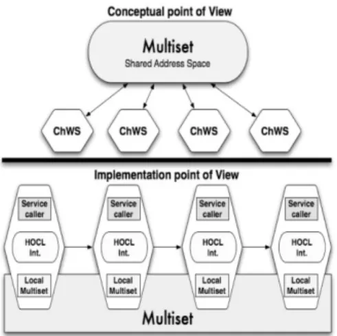
Figure 2: Chemical workflow. Figure 3: Points of view of the architecture.
From an implementation point of view, the multiset is physically distributed. While ap-parently, each ChWS only interacts with the multiset, physically, data and control information (molecules and reaction rules of the multiset) are effectively transferred between local storages of ChWSes. Put together, the molecules stored by ChWS form the multiset. Figure 3 summarizes these two points of view: the upper side shows the conceptual point of view where all ChWSes are connected through one multiset; the lower part shows the implementation point of view where
1.01 h // Multiset (Solution) 1.02 ChWSi:h. . . i // ChWS (Sub-solution) 1.03 ChWSi+1:h. . . i 1.04 . . . 1.05 ChWSn:h . . . i 1.06 i
Figure 4: Chemical workflow representation (left), Simple workflow example (right). all ChWSes are directly interconnected through the multiset, the reactions and molecules being directly transferred from one ChWS to another one using a distributed multiset. In this paper, we will assume that distributing the shared space is possible and will focus on decentralizing the coordination processing itself. Please refer to [25] for more information on how to distribute the shared space. Figure 3 provides a simple example where all ChWS are connected through a sequential workflow (modeled by arrows), but any workflow pattern could be modeled, as we detailed in our previous work [15].
2.2
Chemical Workflow Representation
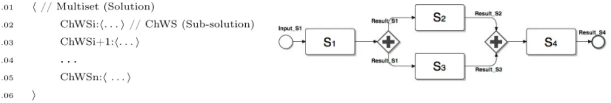
In order to express all data and control dependencies of a workflow definition according to the chemical paradigm and to distribute the information among ChWSes, we use a series of chemical abstractions inspired by the work in [23]. These abstractions allow representing a workflow definition with the HOCL language. Such a representation is given in Figure 4(left).
As a chemical expression, the whole solution represents the multiset containing all informa-tion. The solution itself is composed of as many sub-solutions as ChWSes. Each sub-solution represents a ChWS with its data and control dependencies with other ChWSes within the work-flow definition. More formally, a ChWS is one molecule of the form ChW Si : h. . . i where ChWSi refers to the symbolic name given to the service whose connection details and physical position are hidden, as shown in Figure 4(left).
Let us consider a simple workflow expressed using BPMN (Business Process Modeling
Nota-tion) [28], and composed of the four services S1, S2, S3and S4, as illustrated in Figure 4(right).
In this example, after S1 completes, S2and S3 can be invoked in parallel. Once S2 and S3have
both completed, S4can be invoked.
The corresponding chemical representation for this workflow is presented in Figure 5. As we already mentioned, the solution contains as many sub-solutions as Web services. ChW S1 :
h. . . i to ChW S4 : h. . . i represent ChWSes in the solution. The relations between ChWSes
are expressed through molecules of the form Dest:ChWSi with ChW Si being the destination ChWS where some information needs to be transferred. For instance, we can see in ChW S1 sub-solution that ChWS1 will transfer some information (the outcome of ChWS1) to ChWS2 and ChWS3 (Line 2.02).
Let us focus on the details of these dependencies. ChWS2 has a data dependency: it requires
a molecule Result:ChWS1:value1 containing the result of S1 to be invoked (second part of
Line 2.03). The two molecules produced by the reaction represent the call to S2 and their
input parameters. They are expressed using a molecule of the form Call:Si, and a molecule
Param:hin1,...,inni, where in1, ..., inn represent the input parameters to call the service Si. In
Figure 5, this input parameter corresponds to the result of some previous service Sj. ChWS3
works similarly.
2.01 h // Multiset (Solution)
2.02 ChWS1:hDest:ChWS2, Dest:ChWS3i, // (Sub-solution)
2.03 ChWS2:hDest:ChWS4, replace Result:ChWS1:value1 by Call:S2, Param:h(value1)i i,
2.04 ChWS3:hDest:ChWS4, replace Result:ChWS1:value1 by Call:S3, Param:h(value1)i i,
2.05 ChWS4:hreplace Result:ChWS2:value2, Result:ChWS3:value3 by Call:S4, Param:h(value2)i
2.06 i
Figure 5: Example of a chemical workflow representation.
ChWS4. As specified by Figure 4(right), ChWS4 needs to wait until ChWS2 and ChWS3 have been completed. This constitutes a control dependency known as synchronization. However,
as we can see in line 2.05, the service S4 is invoked only on value2 which is the result of
S2. This constitutes a data dependency. The ChW S4 sub-solution contains one reaction rule
translating those dependencies in chemical language (see line 2.05): the presence of molecules Result:ChWS2:value2 and Result:ChWS3:value3 inside the ChW S4 sub-solution expresses the fulfillment of the control dependencies, to start its own execution. In addition, a data
dependency is also expressed in ChWS4: the result of S2 is required to call S4. During the
execution, as soon as Result:ChWS2:value2 and Result:ChWS3:value3 appear in the ChW S4 sub-solution, the local engine of ChWS4 will be able to perform the reaction that will produce
two new molecules of the form Call:S4 and Param:h (value2) i to call the effective service S4
on the input value2.
To sum up, one reaction rule can express both control and data dependencies. In contrast with the previous synchronization pattern, the simple data dependencies are enough to express the
parallel split pattern of S1 with S2 and S3. Thanks to the implicit parallelism of the chemical
execution model, the reaction rules inside ChW S2 and ChW S3 can be executed in parallel.
Therefore, ChWS2 and ChWS3 will receive the result of S1 from ChWS1 and the invocation of
S2 and S3 will take place in parallel.
This fragment of HOCL code is the chemical representation of a workflow, that will be interpreted by chemical local engines, performing the decentralized execution of this workflow thanks to a set of generic rules we introduce in the next sections.
2.3
Generic Rules for Invocation and Transfer
As previously mentioned, to ensure the execution of a chemical workflow, additional chemical
generic rules (i.e., independent of any workflow) must be defined. These rules are included in
the chemical local engines and are responsible for the efficient execution of the workflow. We now review three of these generic rules, illustrated in Algorithm 1, responsible for these tasks, and that will be commonly encountered in the compositions presented later. The invokeServ rule encapsulates the actual invocation of services. When reacting, it invokes the Web Service
Si, by consuming the tuples Call:Si representing the invocation itself, and Param:hin1,...,inni
representing its input parameters, and generates the molecules containing the results of the invocation in the ChWSi sub-solution. The molecule Flag_Invoke is a flag whose presence in the solution indicates that the invocation can take place. The preparePass rule is used for preparing the messages to transfer the results to their destination services, that will later trigger the execution of the passInfo rule. Thus, the preparePass rule captures one molecule of the form ChWSi:hResult:ChWSi:hvaluei, Dest:ChWSj, ω i. Result:ChWSi:hvaluei is the result
of Si, while Dest:ChWSj comes from the chemical specification of the workflow such as the one
presented in Figure 5.
Algorithm 1Basic generic rules.
3.01 let invokeServ = replace ChWSi:hCall:Si, Param:hin1, . . . , inni, Flag_Invoke, ω i, 3.02 by ChWSi:hResult:ChWSi:hvaluei, ω i
3.03 let preparePass = replace ChWSi:hResult:ChWSi:hvaluei, Dest:ChWSj, ωi
3.04 by ChWSi:hPass:ChWSj:hCompleted:ChWSi:hvaluei i, ωi
3.05 let passInfo = replace ChWSi:hPass:ChWSj:h ω1i, ω2i, ChWSj:h ω3i 3.06 by ChWSi:h ω2i, ChWSj:h ω1, ω3i
a molecule ChWSi:hPass:d:hω1 ii that indicates that some molecules (here denoted ω1) from
ChWSi needs to be transferred to d. These molecules, once inside the sub-solution of d will
trigger the next step of the execution. Therefore, the molecule ω1 will be transferred from
sub-solution ChWSi to sub-solution ChWSj, when reacting with passInfo rule.
Thanks to these reaction rules, the execution of a chemical workflow is decentralized since each ChWS is able to execute rules using its embedded HOCL interpreter, each ChWS achieving the coordination related to the service it encapsulates. However, they can not, by themselves,
solve how to distribute the workflow patterns responsibilities among participants1. Accordingly,
we defined a set of generic rules for solving complex workflow pattern, as detailed in our work [13]. We do not include them here, as the chemical definition of complex workflow structures is not our main concern in this paper.
3
Execution Example
To better understand how the coordination between chemical engines works, we here present a workflow example, illustrated in Figure 5, for which we focus on each step of the coordination logic. These steps are listed in Figures 6 (steps 1-3), 7 (steps 4-7) and 8 (steps 8-10). Recall that, thanks to the higher-order property, reaction rules react themselves with other molecules. Recall that an example composed by four ChWSes applying parallel split and synchronization patterns is illustrated in Figure4(right). The execution is as follows: After ChWS1 completes, it forwards the result to ChWS2 and ChWS3 in parallel. Once ChWS2 and ChWS3 have completed, ChWS4 can start. Consider that each chemical local engine is responsible for the reactions taking place within its sub-solution in the multiset, thus respecting at runtime the decentralization designed. Indeed, for the sake of clarity, we only mention the molecules that take part in the logic of the coordination.
The first step (Lines 4.02-4.05) corresponds to the initial state of the multiset, illustrated in Figure 6. Initially, the only possible reaction is inside ChWS1, the invokeServ rule is triggered by the HOCL interpreter of ChWS1, producing the outcome molecule Result:ChWS1:hvali. This
molecule represents the result of the invocation of S1. Then, the preparePass rule consumes the
molecules Dest:destination and Result:ChWS1:hvali, preparing the parallel split. Therefore, it produces two new molecules for the distribution of this result to ChWS2 and ChWS3 (Lines 4.20-4.21). Finally, still through ChWS1, passInfo triggers it by transferring in parallel the outcome of ChWS1.
Once the information is received by ChWS2 and ChWS3, the reactions (Lines 5.04 and 5.06)
are triggered, in parallel, producing the needed molecules to invoke S2 and S3. Thus, molecules
of the form Call:Si and Param:(val) contained into ChWS2 and ChWS3 respectively, launch
the invokeServ rule (Lines 5.03-5.05) that generates the result of S2and S3. Similarly to ChWS1,
the molecules Result:ChWS2:hval2i and Result:ChWS3:hval3i react with the preparePass rule.
4.01h
4.02ChWS1:hDest:ChWS2,Dest:ChWS3, invokeServ, preparePass, passInfo, Call:S1, Param:in1i,
4.03ChWS2:hDest:ChWS4, invokeServ, preparePass, passInfo, replace Completed:ChWS1:hvali by Call:S2, Param:(val)i,
4.04ChWS3:hDest:ChWS4, invokeServ, preparePass, passInfo, replace Completed:ChWS1:hvali by Call:S3 Param:(val)i,
4.05ChWS4:hinvokeServ, replace Completed:ChWS2:hval2i, Completed:ChWS3:hval3i by Call:S4, Param:(val2)i
4.06i
↓
4.07h
4.08ChWS1:hDest:ChWS2,Dest:ChWS3, preparePass, passInfo, invokeServ, Call:S1, Param:in1 i,
4.09ChWS2:hDest:ChWS4, invokeServ, preparePass, passInfo, replace Completed:ChWS1:hvali by Call:S2, Param:(val)i,
4.10ChWS3:hDest:ChWS4, invokeServ, preparePass, passInfo, replace Completed:ChWS1:hvali by Call:S3 Param:(val)i,
4.11ChWS4:hinvokeServ, replace Completed:ChWS2:hval2i, Completed:ChWS3:hval3i by Call:S4, Param:(val2)i
4.12i
↓
4.13h
4.14ChWS1:hDest:ChWS2,Dest:ChWS3, preparePass, passInfo, Result:ChWS1:hvalii,
4.15ChWS2:hDest:ChWS4, invokeServ, preparePass, passInfo, replace Completed:ChWS1:hvali by Call:S2, Param:(val)i,
4.16ChWS3:hDest:ChWS4, invokeServ, preparePass, passInfo, replace Completed:ChWS1:hvali by Call:S3 Param:(val)i,
4.17ChWS4:hinvokeServ, replace Completed:ChWS2:hval2i, Completed:ChWS3:hval3i by Call:S4, Param:(val2)i
4.18i
↓
4.19h
4.20ChWS1:hpassInfo, Pass:ChWS2:hCompleted:ChWS1:hvali i, Result:ChWS1:hvali,
4.21 Pass:ChWS3:hCompleted:ChWS1:hvali i i,
4.22ChWS2:hDest:ChWS4, invokeServ, preparePass, passInfo, replace Completed:ChWS1:hvali by Call:S2, Param:(val)i,
4.23ChWS3:hDest:ChWS4, invokeServ, preparePass, passInfo, replace Completed:ChWS1:hvali by Call:S3 Param:(val)i,
4.24ChWS4:hinvokeServ, replace Completed:ChWS2:hval2i, Completed:ChWS3:hval3i by Call:S4, Param:(val2)i
4.25i
5.01 h
5.02 ChWS1:hResult:ChWS1:hvali i,
5.03 ChWS2:hDest:ChWS4, invokeServ, preparePass, passInfo, Completed:ChWS1:hvali,
5.04 replace Completed:ChWS1:hvali by Call:S2, Param:(val)i,
5.05 ChWS3:hDest:ChWS4, invokeServ, preparePass, passInfo, Completed:ChWS1:hvali,
5.06 replace Completed:ChWS1:hvali by Call:S3, Param:(val)i,
5.07 ChWS4:hinvokeServ, replace Completed:ChWS2:hval2i, Completed:ChWS3:hval3i by Call:S4, Param:(val2)i
5.08 i
↓
5.09 h
5.10 ChWS1:hResult:ChWS1:hvali i,
5.11 ChWS2:hDest:ChWS4, invokeServ, preparePass, passInfo, Call:S2, Param:(val)i,
5.12 ChWS3:hDest:ChWS4, invokeServ, preparePass, passInfo, Call:S3, Param:(val)i,
5.13 ChWS4:hinvokeServ, replace Completed:ChWS2:hval2i, Completed:ChWS3:hval3i by Call:S4, Param:(val2)i
5.14 i
↓
5.15 h
5.16 ChWS1:hResult:ChWS1:hvali i,
5.17 ChWS2:hDest:ChWS4, Result:ChWS2:hval2i, preparePass, passInfoi,
5.18 ChWS3:hDest:ChWS4, Result:ChWS3:hval3i, preparePass, passInfoi,
5.19 ChWS4:hinvokeServ, replace Completed:ChWS2:hval2i, Completed:ChWS3:hval3i by Call:S4, Param:(val2)i
5.20 i
↓
5.21 h
5.22 ChWS1:hResult:ChWS1:hvali i,
5.23 ChWS2:hPass:ChWS4:hCompleted:ChWS2:hval2i i, passInfo, Result:ChWS2:hval2i i,
5.24 ChWS3:hPass:ChWS4:hCompleted:ChWS3:hval3i i, passInfo, Result:ChWS3:hval3i i,
5.25 ChWS4:hinvokeServ, replace Completed:ChWS2:hval2i, Completed:ChWS3:hval3i by Call:S4, Param:(val2)i
5.26 i
Figure 7: Workflow execution, steps 4-7.
Finally, in ChWS2 and ChWS3, the passInfo rule propagates the molecule Pass:ChWS4:h
infor-mation ito ChWS4 (Lines 5.23-5.24).
The execution ends with steps in Figure 8, processed by ChWS4’s local engine. Once the information from ChWS2 and ChWS3 is received by ChWS4, the reaction rule (Line 6.04) can
react with results molecules to produce two new molecules for invoking service S4 (Line 6.08).
Finally, invokeServ rule will take place producing the final result Result:ChWS4:hval4i. With this example, we have shown that local engines within ChWSes are co-responsible for applying workflow patterns, invoking services, and propagating the information to other ChWSes. The coordination is achieved as reactions become possible, in an asynchronous and decentralized manner.
6.01 h
6.02 ChWS1:hResult:ChWS1:hvali i, ChWS2:hResult:ChWS2:hval2i i, ChWS3:hResult:ChWS3:hval3i i, 6.03 ChWS4:hinvokeServ, Completed:ChWS2:hval2i, Completed:ChWS3:hval3i,
6.04 replace Completed:ChWS2:hval2i, Completed:ChWS3:hval3i by Call:S4, Param:(val2)i
6.05 i
↓
6.06 h
6.07 ChWS1:hResult:ChWS1:hvali i, ChWS2:hResult:ChWS2:hval2i i, ChWS3:hResult:ChWS3:hval3i i,
6.08 ChWS4:hinvokeServ, Call:S4, Param:(val2)i
6.09 i
↓
6.10 h
6.11 ChWS1:hResult:ChWS1:hvali i, ChWS2:hResult:ChWS2:hval2i i, ChWS3:hResult:ChWS3:hval3i i,
6.12 ChWS4:hResult:ChWS4:hval4i i
6.13 i
Figure 8: Workflow execution, steps 8-10.
4
Software Prototype
To put in practice and validate the concepts presented, we have developed an architectural frame-work and two software prototypes exhibiting different processing and communication techniques. Firstly, we developed a decentralized, shared space-based architecture inspired by that presented in Section 2. This architecture is composed of a set of chemical engines collaborating through a multiset acting as a shared space. Service interactions are loosely coupled, a property inherited by the adoption of the tuplespace model. The computation is decentralized (even if the mul-tiset remains a centralized.) Secondly, and for the sake of comparison and discussion, we also developed a centralized architecture, which is composed of a unique chemical engine playing the same role as traditional workflow engines. Both prototypes are written in Java and built atop an HOCL interpreter based on on-the-fly compilation of HOCL specifications [27]. The table below summarizes them:
Centralized Arch. Decentralized Arch. Workflow execution Centralized Decentralized Multiset Centralized Centralized (shared space) Communication Loosely coupled Loosely coupled
4.1
Centralized version
Following the examples of most of workflow management systems, the coordination can be man-aged by a single node, referred to as the chemical workflow service, as illustrated by Figure 9.
As mentioned in Section 2, the workflow definition is executed as a chemical program by the chemical workflow service. The low layer of the architecture is an HOCL interpreter. Given a workflow specification as input (an HOCL program), it executes the workflow coordination by reading and writing the multiset initially fed with the workflow definition. The interface between the chemical engine and the distant services themselves is realized through the service
allowing the dynamic connection to different flavors of services (SOAP or RESTFul), abstracting the target service’s internals. DAIOS was specially extended with a module which automatically generates dynamic bindings, as well as input and output messages required between the chemical engine and a Web service.
4.2
Decentralized version
This framework is similar to the previous architecture, however the functionality of the multiset represents the main difference with the centralized version, as illustrated by Figure 10. The multiset is initially fed with the HOCL specification of the workflow. The multiset acts as a shared space playing the role of a communication medium and a storage system, while each ChWS
involved will take its part in the coordination process. As such, the coordination workload2 is
now distributed among the ChWSes participating in the workflow.
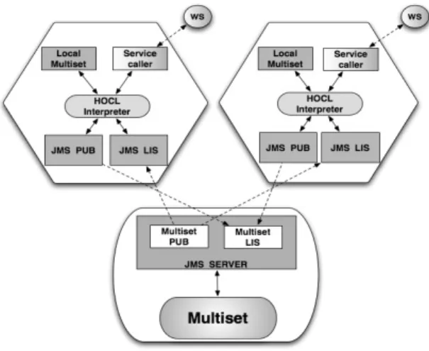
As we detailed in Section 2.2, the workflow definition is comprised of one sub-solution per WS involved; the information in one sub-solution can only be accessed by the ChWS owner of/represented by that sub-solution. On each ChWS, a local storage space acts as a temporary container for the sub-solution to be processed by the local HOCL interpreter. The interface between a ChWS and a concrete WS is still realized through the service caller based on the DAIOS framework. ChWSes communicate with the multiset through the Java Message Service (JMS) publisher/subscriber modules. The multiset is encapsulated into a JMS server to allow concurrent reading and writing operations by ChWSes. Periodically, and independently from each other, ChWSes read their sub-solution from the multiset. The sub-solution obtained is then locally processed by the ChWS’s local HOCL interpreter and then pushed back to the multiset for update.
Figure 9: Centralized architecture. Figure 10: Decentralized architecture.
This architecture follows a loosely coupled interaction model, as ChWSes only keep a reference to the shared space, instead of having a reference to each ChWS with which they interact.
2The coordination workload includes all the workflow operations related with the processing of workflow structures.
4.2.1 Communications
As mentioned above, communication mechanisms are implemented with JMS. JMS modules are included into the ChWSes, and the multiset is a JMS server.
The publish/subscribe messaging model is used by the ChWSes and the multiset whereby message producers called publishers pushing each message to each interested party called sub-scribers. Initially, the Multiset PUBlisher pushes the content of each W Si solution to each
ChWSes LIStener. On the ChWS’s side, the ChWS LIStener receives the content of the ChWSi
solution which will be copied into its local multiset. Once the HOCL interpreter is done with its execution, the ChWS PUBlisher pushes the content of its sub-solution into the Multiset LIStener. Recall that the decentralized architecture is distributed, a JMS server into the multiset is needed to coordinate all these messages. Concretely, we use ActiveMQ (version 5.4.1) an im-plementation of the JMS 1.1 specification, which can be embedded in a Java application server. This ActiveMQ server allows to register and save all the message exchanges between subscribers and publishers. The message exchanged are stored in the server, allowing them to be used in the future if a problem arises during the transaction.
5
Experimental Results
Our objective is here to better capture the behavior of a decentralized chemistry-based workflow system. To achieve it, we processed workflows with different characteristics using our central-ized and decentralcentral-ized prototypes. These characteristics are the number of tasks involved, the
amount of data exchanged and the complexity of the coordination required3. Experiments were
conducted over the nation-wide Grid’5000 platform [9]. More specifically, these experiments were conducted on the parapide, paramount and paradent clusters, located in Rennes. The parapide cluster is composed of nodes equipped with two quad-core Intel Xeon X5570, 24 GB of RAM; the
paramount cluster provides nodes with two quad-core Intel Xeon L5148 LV processors, 30 GB
of RAM, and the paradent cluster is equipped with two quad-core Intel Xeon L5420 processors. All three clusters are furnished with 40GB InfiniBand Ethernet cards.
5.1
Workflows Considered
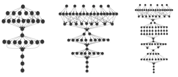
Three workflows containing 30, 60 and 100 tasks were designed inspired by the graph of the Montage workflow [7], a classic astronomical image mosaic workflow processing large images of the sky. Montage combines sequential and parallel flows, making it relevant for such experiments. Our variants of the Montage workflow are illustrated in Figure 11, Figure 12 and Figure 13, and are respectively referred to as Workflow30t, that comprises 30 tasks over 10 levels (the level of a task is defined as the length of the path leading to it from the source task),Workflow60t, that comprises 60 tasks dispatched over 13 levels, and Workflow100t made of 100 tasks of 19 levels. Our campaign has the following considerations:
1. Each task calls an actual web service.
2. Tasks at the same level have the same computational cost. 3. The results of these experiments are averaged over 10 runs.
4. Each task is run by one distinct machine on the Grid’5000 platform.
3Informally, we consider as a complex workflow, a workflow having many patterns to be applied and a high rate of data exchange. Workflows are more precisely described in the following.
Figure 11: 30-task graph. Figure 12: 60-task graph. Figure 13: 100-task graph. Three different web services were built, needing different amounts of data exchanges, for one call to this service, namely 28 bytes for serviceA, 583 bytes for serviceB, and 3063 bytes for
serviceC. The definitions used for each workflow are available online4.
5.2
Managing Large Workflows
In this experiment, we utilized our centralized and decentralized prototypes to process the
Wor-flow30t, Workflow60t and Workflow100t. To create a more heterogeneous scenario, we also
decided to repeat these workflows using the serviceA, serviceB and serviceC.
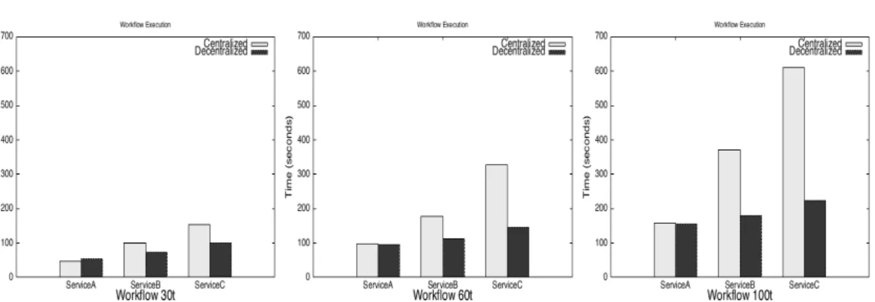
When looking at the results shown on Figures 14, 15, and 16, we can draw several conclu-sions. Firstly, the size of each of these workflows affects its execution time. The Workflow30t presents lower execution times than the Workflow60t, and Workflow100t, independently of the workflow management systems utilized. Secondly, the difference of performance between the centralized and decentralized engines is very low when serviceA is used. Then, when shifting to services with a higher amount of data exchanged, the performance of the centralized approach drops significantly. Finally, when using the decentralized workflow system, the Workflow60t and
Workflow100t presents an important improvement in the performance.
In contrast, our centralized workflow system shows a substantial increase of the execution time caused by the two aforementioned factors: the number of tasks to be coordinated, and the type of service. This suggests that the efficiency of an engine is affected by the amount of data exchanged among services participating in a workflow. Obviously, a central engine is in charge of the management of all data exchanged between services, increasing the processing time of a workflow.
5.2.1 Coordination Workload
Let us now focus on the results of each workflow using the centralized engine in Figure 17. Here, we extracted from the total execution time, the cost in time of the coordination activities (denoted by Coordination), and the execution time required by the web services to return the results of their invocations (denoted by Service invocation). Informally, we consider as coordination
activities, all the operations managing the data exchanged among tasks and applying the different
Figure 14: Workflow30t Figure 15: Workflow60t Figure 16: Workflow100t workflow patterns. Consequently, the coordination time will increase depending on the number and complexity of patterns to be applied and the rate of data exchanged.
As observed in Figure 17, the processing time spent in coordination activities represents the majority of the total execution time in all the workflows. This phenomenon shows the importance of the engines to efficiently handle workflows with a substantial coordination workload. As an example, the centralized engine seems saturated when processing the coordination activities of the Workflow100t using the serviceC. Furthermore, this graph also shows similar execution times regarding the service invocation in each workflow (independently of the type of service), so that these times can be omitted in the following, as they mostly remain constant for both prototypes. Therefore, we focus on the coordination time employed for each prototype to process the different workflows, as it allows us to identify the benefits behind the decentralized workflow execution.
Figure 17: Centralized execution: ratio
be-tween coordination and invocation. Figure 18: Performance results, data ex-change.
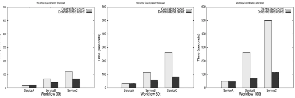
The coordination times employed by both centralized and decentralized workflow systems are now discussed in Figure 19. It shows a reduction in the coordination times spent by the decen-tralized system in comparison to the cendecen-tralized one. This improvement in the performance is
achieved due to the coordination workload is distributed among the different engines, reducing the final execution time. In contrast to that of a centralized workflow engine, the coordination workload is managed by a single node, thus explaining the increment in the coordination time ex-perienced for the workflows with the serviceB and serviceC. As we mentioned before, the benefits behind the decentralized workflow execution can be observed when processing the Workflow60t and Workflow100t using the serviceB and serviceC, respectively. However, the use of the
ser-viceAin the workflows do not offer any gain due to its simplicity, the reduced computational
load of this workflow provokes that the coordination time is higher than or equal to that of the centralized engine, due to the communications (network latency).
Figure 19: Coordination workload: centralized vs decentralized
5.3
Exchanging Data
For the second experiment, we have dealt with different amounts of data exchange using the decentralized prototype. We processed six workflows based on the Workflow30t graph, whose tasks are bounded to the same web service. For each workflow, we measured the performance using a set of web services exchanging different amounts of data for their execution. This set of services is composed by the three previously-mentioned services and by three others. Thus, experiments were conducted with services exchanging respectively 28, 583, 3053, 5053, 9773, and 15000 bytes of data. The performance obtained accordingly is illustrated in Figure 18.
As we can see in Figure 18, the increase in data exchange among tasks provokes an increase of the execution time, and suggests a polynomial degradation of the performance when the size of information exchanged increases. Nevertheless, no bottlenecks have been experienced, even if it may appear with higher data rate. The degradation occurs because the information exchanged is considered itself as a molecule in our chemical model, to be transferred and processed in the multiset. Note that, the number of messages exchanged was not measured in the experiments. However, it can be easily deduced by the number of tasks of a workflow (106 messages for the
Workflow30t). Besides, the number of messages exchanged is the same for both centralized and
decentralized systems.
5.4
Discussion
This series of experiments, by offering a proof of concept of the model, while showing its viability in actual deployments, highlights the benefits of a decentralized (chemistry-based) workflow sys-tem. Our decentralized workflow engine processes large workflows with a reduced coordination
overhead in comparison with a centralized engine. Using the decentralized engine, the coordina-tion is executed locally on each ChWS, instead of being managed by a single node. Furthermore, as shown in our previous work [13], our decentralized engine is also competitive when running real scientific applications in comparison with most common and used workflow management systems.
However, there are two limitations that come up when using our decentralized workflow system: i) the network latency causes performance degradations, which are emphasized when processing workflows having a reduced computational load such as the Workflow30t; ii) the multiset could constitute a bottleneck. It remains a centralized space shared by every ChWSes leading to potential scalability issues. Following this idea, our approach may experience some performance bottleneck when the rate of data exchange among services becomes very high. The decentralization of the multiset itself was recently addressed through the formulation of solutions based on peer-to-peer protocols, able to distribute and retrieve objects (here, molecules) at large-scale [25]. One of the next steps of this work is to build our current decentralized prototype on top of such approaches to remove the bottleneck problem, and proposes a fully decentralized workflow engine.
Recall, beyond performance or optimization considerations, that the chemical models provide all the needed abstractions to naturally express both data-driven and complex control-driven execution, including particular features like cancellation. Please refer to [16] for more details. We consider the chemical abstraction as participating in the long term objective of improving the workflow execution models on emerging platform, like clouds, where the elasticity brings new modeling challenges.
6
Related Works
There is a vast literature related to the distributed execution of workflows. We observed two methods of distributed coordination approach. In the first one, nodes interact directly. In the second one, they use a shared space for coordination.
Earlier works proposed decentralized architectures where nodes achieve the coordination of a workflow through the exchange of messages [32, 22]. Some works, such as [8, 21, 34], shown the increasing interest in this type of coordination mechanism. In [8], the authors introduce service invocation triggers, a lightweight infrastructure that routes messages directly from a producing service to a consuming one, where each service invocation trigger corresponds to the invocation of a service. In [21], an engine is proposed based on a peer-to-peer application architecture wherein nodes (similar to local engines) are distributed across multiple computer systems, but appear to the users as a single entity. These nodes collaborate, in order to execute a composite Web service with every node executing a part of it. Lately, a continuation-passing style, where information on the remainder of the execution is carried in messages, has been proposed [34]. Nodes interpret such messages and thus conduct the execution of services without consulting a centralized engine. However, this coordination mechanism implies a tight coupling of services in terms of spatial and temporal composition. Nodes need to know explicitly which other nodes they will potentially interact with, and when, to be active at the same time. Likewise, a distributed workflow system based on mobile libraries playing the role of engines was presented in [12]. The authors, however, do not give much details about the coordination itself, and where the data and control dependencies are located.
Our works deal with the information exchange among ChWSes by writing and reading the multiset. Then, the communication can be completely asynchronous since the multiset guarantees the persistence of data and control dependencies. This makes our approach more relevant in a
loosely-coupled services environment, and able to deal with dynamic changes in the workflow (as the workflow itself can be rewritten in the multiset).
Another series of works rely on a shared space to exchange information between nodes of a decentralized architecture, more specifically called a tuplespace [10, 20, 30, 19]. Its origin can be found in the coordination data-driven languages such as Linda [17], as a parallel programming extension for programming languages for the purpose of separating coordination logic from pro-gram logic. Linda builds upon the notion of a tuplespace, which is a piece of memory shared by all interacting parties. Using a tuplespace for coordination, the execution of a part of a workflow within each node is triggered when tuples, matching the templates registered by the respective nodes, are present in the tuplespace. In the same vein, works such as [24], propose a distributed architecture based on Linda where distributed tuplespaces store data and programs as tuples, allowing mobile computations by transferring programs from one tuple to another. However, the chemical paradigm allows an increased abstraction level while providing support for dynamics.
Based on this coordination method, works such as [10], [20] and [30] replace a centralized BPEL engine by a set of distributed, loosely coupled, cooperating nodes. In [10] and [20], the authors present a coordination mechanism where the data is managed using a tuplespace and the control is driven by asynchronous messages exchanged between nodes. This message exchange pattern for the control is derived from a Petri net expression of the workflow. However, while in these works, the tuplespace is only used to store data information, our coordination mechanism stores both control and data information in the multiset, which is made possible by the use of the chemical execution model for the coordination of all data and control dependencies.
As a continuation of [20], [19] designed and implemented a tuplespace-based process execution middleware that transforms a workflow definition into a set of activities. Using this system, control and data dependencies are now stored in the tuplespace. Activities are distributed by passing tokens in the Petri net that formalize of the tuplespace-based interactions. The most significant difference with the present work, however, is the general goal. The authors focused on the process definition and the viability of its prototype, while its experimental validation remains a wide open issue, in particular related to scalability. Also, they do not discuss the advantages and disadvantages of decentralization in workflow processing. Similarly, based on the theoretical underpinnings and core of the engine presented in [19], the work in [30] uses a shared tuplespace working as a communication infrastructure, allowing to exchange control and data dependencies among processes and make the different nodes interact. The authors transform a centralized BPEL definition into a set of coordinated processes using again the tuplespace as a communication medium. However, the use of BPEL as the coordination language hinders from expressing dynamic and self-adaptive behaviors.
As a more general comment, to our knowledge, these works do not provide any experimental validation of running workflows on distributed infrastructures.
7
Conclusion
Most of today’s approaches to the coordination of composite Web services are based on highly centralized architectures. Such systems present several drawbacks, mainly dealing with scala-bility, fault-tolerance, and privacy. In order to tackle these issues, it becomes today crucial to propose decentralized coordination mechanisms. However, current proposals for decentralized workflow coordination require tight coupling of services, and use workflow description languages that do not provide concepts for distributed workflow execution.
In this paper, we have proposed a high-level coordination mechanism allowing a distributed execution of composite Web services, based on the chemical metaphor. Our chemical
program-ming paradigm expresses parallelism and autonomic behaviors naturally using a higher-order chemical language. We have introduced the notion of chemical Web service, which encapsulates a Web service. Through a shared multiset containing the information on both data and control dependencies needed for coordination, chemical Web services are co-responsible for carrying out the execution of a workflow in the composite services in which they appear. Spatial and temporal composition of services is achieved dynamically through this shared multiset. Their coordination is decentralized and distributed among individual Web service’s chemical engine executing a part of the workflow.
Through the deployment of a software prototype following these concepts, and its experimen-tal validation over an actual platform, we have been able to provide a proof of concept while showing its viability and identifying its performance limitations for its future improvement.
References
[1] Amazon’s outage in third day: debate over cloud computing’s future begins.
[2] Web services business process execution language, (WS-BPEL), Version 2.0. OASIS Stan-dard, 2007.
[3] Gustavo Alonso, C. Mohan, Divyakant Agrawal, and Amr El Abbadi. Functionality and limitations of current workflow management systems. IEEE Expert, 12, 1997.
[4] Jean-Pierre Banâtre, Pascal Fradet, and Yann Radenac. Generalised multisets for chemical programming. Mathematical Structures in Computer Science, 16(4):557–580, 2006.
[5] Jean-Pierre Banâtre and Daniel Le Métayer. The gamma model and its discipline of pro-gramming. Sci. Comput. Program., 15(1):55–77, 1990.
[6] Jean-Pierre Banâtre, Thierry Priol, and Yann Radenac. Chemical Programming of Future Service-oriented Architectures. Journal of Software, 4(7):738–746, 2009.
[7] G. Berriman, Ewa Deelman, John Good, Joseph Jacob, Daniel Katz, Carl Kesselman, Anas-tasia Laity, Thomas Prince, Gurmeet Singh, and Mei hu Su. Montage: A grid enabled engine for delivering custom science-grade mosaics on demand. In Proceedings of SPIE Conference
5487: Astronomical Telescopes, 2004.
[8] Walter Binder, Ion Constantinescu, and Boi Faltings. Decentralized orchestration of com-positeweb services. In Proc. of the IEEE Int. Conference on Web Services, pages 869–876. IEEE Computer Society, 2006.
[9] Raphael Bolze, Franck Cappello, Eddy Caron, Michel J. Daydé, Frédéric Desprez, Emmanuel Jeannot, Yvon Jégou, Stéphane Lanteri, Julien Leduc, Nouredine Melab, Guillaume Mornet, Raymond Namyst, Pascale Primet, Benjamin Quétier, Olivier Richard, El-Ghazali Talbi, and Iréa Touche. Grid’5000: A large scale and highly reconfigurable experimental grid testbed. IJHPCA, 20(4):481–494, 2006.
[10] Paul A. Buhler and Jose M. Vidal. Enacting BPEL4WS specified workflows with multiagent systems. In Proceedings of the Workshop on Web Services and Agent-Based Engineering, 2004.
[11] Girish Chafle, Sunil Chandra, Vijay Mann, and Mangala Gowri Nanda. Decentralized orchestration of composite web services. In Proceedings of the 13th International World
[12] Patrick Downes, OisÃn Curran, John Cunniffe, and Andy Shearer. Distributed radiotherapy simulation with the webcom workflow system. Int. Journal of High Performance Computing
Applications, 24:213–227, 2010.
[13] Héctor Fernandez. Flexible Coordination based on the Chemical Metaphor for Service
In-frastructures. These, Université Rennes 1, June 2012.
[14] Hector Fernandez, Thierry Priol, and Cédric Tedeschi. Decentralized approach for execution of composite web services using the chemical paradigm. In IEEE International Conference
on Web Services (ICWS), pages 139–146, 2010.
[15] Hector Fernandez, Cédric Tedeschi, and Thierry Priol. Decentralized workflow coordination through molecular composition. In ICSOC Workshops, pages 22–32, 2011.
[16] Héctor Fernández, Cédric Tedeschi, and Thierry Priol. Self-coordination of Workflow Exe-cution Through Molecular Composition. Research Report RR-7610, INRIA, 05 2011. [17] David Gelernter and Nicholas Carriero. Coordination languages and their significance.
Com-mun. ACM, 35(2):96–107, 1992.
[18] Philipp Leitner, Florian Rosenberg, and Schahram Dustdar. Daios: Efficient dynamic web service invocation. IEEE Internet Computing, 13(3):72–80, 2009.
[19] Daniel Martin. A tuplespace based execution model for decentralized workflow enactment :
applied for BPEL. PhD thesis, University of Stuttgart , Germany, September 2010.
[20] Daniel Martin, Daniel Wutke, and Frank Leymann. A novel approach to decentralized workflow enactment. In IEEE International Enterprise Distributed Object Computing
Con-ference, pages 127–136, Los Alamitos, CA, USA, 2008. IEEE Computer Society.
[21] Rosa Anna Micillo, Salvatore Venticinque, Nicola Mazzocca, and Rocco Aversa. An agent-based approach for distributed execution of composite web services. In IEEE International
Workshops on Enabling Technologies, pages 18–23, Los Alamitos, CA, USA, 2008. IEEE
Computer Society.
[22] Mangala Gowri Nanda, Satish Chandra, and Vivek Sarkar. Decentralizing execution of composite web services. In Proc. of the 19th Conf. on object-oriented programming, systems,
languages, and applications, pages 170–187. ACM, 2004.
[23] Zsolt Németh, Christian Pérez, and Thierry Priol. Distributed workflow coordination: molecules and reactions. In 20th International Parallel and Distributed Processing
Sym-posium (IPDPS), 2006.
[24] Rocco De Nicola, Gianluigi Ferrari, and Rosario Pugliese. KLAIM: a kernel language for agents interaction and mobility. IEEE Transactions On Software Engineering, 24, 1997. [25] Marko Obrovac and Cédric Tedeschi. Deployment and evaluation of a decentralised runtime
for concurrent rule-based programming models. In (ICDCN), pages 408–422, 2013.
[26] Jelica Protić, Milo Tomasević, and Veljko Milutinović. Distributed shared memory. John Wiley and Sons, 1998.
[27] Yann Radenac. Programmation “chimique” d’ordre supérieur. Thèse de doctorat, Université de Rennes 1, 2007.
[28] Jan Recker. BPMN modeling – who, where, how and why. BP-Trends, 5(5):1–8, 2008. [29] Michael Rosen, Boris Lublinsky, Kevin T. Smith, and Marc J. Balcer. Applied SOA:
Service-Oriented Architecture and Design Strategies. Wiley, June 2008.
[30] Mirko Sonntag, Katharina Gorlach, Dimka Karastoyanova, Frank Leymann, and Michael Reiter. Process space-based scientific workflow enactment. Int. Journal of Business Process
Integration and Mmgt, 5:32 – 44, 2010.
[31] Mirko Viroli and Franco Zambonelli. A biochemical approach to adaptive service ecosystems.
Information Sciences, pages 1–17, 2009.
[32] Jun Yan, Yun Yang, and Gitesh Raikundalia. Enacting business processes in a decentralised environment with p2p-based workflow support. In Advances in Web-Age Information
Man-agement, pages 290–297. 2003.
[33] Yun Yang. An architecture and the related mechanisms for web-based global cooperative teamwork support. Int. Journal of Computing and Informatics, 24, 2000.
[34] Weihai Yu. Consistent and decentralized orchestration of BPEL processes. In Proceedings
of the 2009 ACM symposium on Applied Computing, pages 1583–1584, Honolulu, Hawaii,