This is an author-deposited version published in: https://sam.ensam.eu Handle ID: .http://hdl.handle.net/10985/9746
To cite this version :
Jérôme DUCHEMIN, Mikhail GUSKOV, Philippe LORONG - Prediction of milling-induced vibrations in machining complex parts : numerical and experimental investigation - 2014
PREDICTION OF MILLING-INDUCED VIBRATIONS IN MACHINING
COMPLEX PARTS: NUMERICAL AND EXPERIMENTAL
INVESTIGATION
Duchemin J. 1, Guskov M. 1, Lorong P.1
1PIMM UMR8006 CNRS, Arts et Métiers ParisTech, Paris 75013, France
jerome.duchemin@ensam.eu , mikhail.guskov@ensam.eu , philippe.lorong@ensam.eu
ABSTRACT
Avoiding vibrations during machining is an important issue for industry. When dealing with chatter prediction with a numerical approach, several models are required: dynamical models of the workpiece and tool, cutting interaction law and surface representation. The resulting model is a trade-off between the complexity of the above-mentioned ingredients in the context of given solution strategy of equations of motion.
Classically, one or two of the above mentioned modeling triad are kept rather rudimentary. These simplifications are often justified depending on the relative importance of phenomena at stake in concrete system. Nevertheless, there are cases when neglecting one of these aspects can lead to considerable alteration in the results (dynamical behavior and resulting machined surface).
In the present work, an integrated approach is proposed in order to combine the use of relatively advanced developments along each modeling aspect: a reduced finite element model (using a basis of modes) of the part and tool for the dynamics, segment-wise analytical cutting laws on discretized matter-erasing cutting edges for tool/workpiece interaction, and at last dexel-based geometrical model for the surface evolution.
The present work is concerned with a face milling operation of an automobile exhaust manifold. Due to the complexity of the geometry of machined surface, this operation takes place under continuously varying conditions in terms of length of tooth path, of number of engaged teeth and of local workpiece dynamic stiffness. Observations of final surface on actual parts include several zones with considerable vibration-induced defects.
Different levels of detail, such as workpiece or tool compliance and damping, are applied in order to appreciate their impacts. The results show that only when flexibility of the part and of the tool are accounted for, the surface defects are close to the reality.
RÉSUMÉ
La maîtrise des vibrations en usinage constitue un chalenge important. Lorsque l'on utilise une approche numérique pour prédire le broutement, plusieurs modèles sont nécessaires : un modèle dynamique de la pièce et de l'outil, un modèle d'interaction outil/matière ainsi qu'un modèle géométrique pour la surface usinée. Le modèle global résultant est un compromis entre complexité de chaque modèle constitutif et exigences de la stratégie choisie pour la résolution des équations de mouvement.
Généralement, un ou deux des trois modèles restent très rudimentaires. La justification des choix faits se base sur une estimation de l'importance relative des phénomènes intervenant dans le comportement du système réel. Cependant, il y a des exemples où ce choix conduit à une détérioration sensible des résultats, aussi bien sur les aspects dynamiques d'état de surface.
Nous proposons ici un approche permettant de combiner des développements relativement avancés pour chacun des modèles constitutifs: un modèle réduit pour le comportement dynamique de l'outil et de la pièce (utilisation d'une base modale réduite), des lois de coupe basées sur une discrétisation des arêtes de coupe pour l'interaction outil/matière et un modèle géométrique utilisant des dexels pour suivre l'évolution de la surface usinée et l'effacement de la matière.
Cet article a pour support d'étude une opération de surfaçage d'un collecteur d'échappement automobile. La complexité de la surface usinée fait que les conditions d'usinage évoluent continuellement : raideur dynamique locale de la pièce sous les dents et nombre de dents engagées. Sur les pièces réelles, après usinage, plusieurs zones comportent des défauts géométriques induits par les vibrations relatives outil/pièces.
L'étude de l'impact sur les résultats de la modélisation du comportement dynamique de la pièce et de l'outil, amortissement et flexibilité, a été évaluée par simulation. Cette étude montre la nécessité de prendre en compte la flexibilité de la pièce et de l'outil pour avoir des résultats proches de la réalité.
1. INTRODUCTION
Machining is generally the weak link of the numerical chain that aims to go from the design of a part to its use. This difficulty comes from the fact that machining is a dynamic process involving complex physical phenomena with thermal and vibrational aspects. The study is generally conducted at two different scales: i) the scale of the tool tip where the separation of the matter leads to thermo-mechanical phenomenon with high strains and high gradient of temperature, in this scale ones are mainly interested in the surface integrity and tool wear, ii) the scale of the part where ones tries to predict the vibrations, or their appearance, and the geometry of the machined surface. At this last scale chatter and discontinuous cutting are among the important causes of vibrations, and since works by Tobias [1], many authors have been working on the subject. Altintas et al. gave an overview of research work dealing with the dynamics of milling and grinding [2] and a description of the concept of the virtual machine tool in [3]. All these topics were surveyed in [4] by Altintas. Brecher et al. [5] presented the state of research on process–machine tool interaction in 2009. The most of the works have the objective of fast stability analysis in the frequency domain or in the context of a periodic solution. These approaches are very useful to optimize cutting condition in order to maximize mass removing or establish stability in slow varying cutting conditions. However for a part having a complex shape, or when being interested in the geometry of the obtained final surface, time-domain simulations are more relevant even if they are more time consuming. The study presented in this paper aims to predict the defects generated on a machined surface of a complex workpiece and uses such a time domain approach. As complex parts are often flexible, generally because of component mass minimization, the dynamic behavior of the workpiece cannot be neglected. Altintas et al [6] and Corduan et al. [7] developed such models of a flexible workpiece in interaction with rigid tools. Coffignal et al. [8,9,10] also included the possibility of tool
deformations in their time-domain approach, but for a simple geometry of the workpiece and three-axis milling. Time-domain five-three-axis milling simulations of the machining of turbine blades, including tool and workpiece vibrations and regenerative forces, were given by Biermann et al. [11]. Recently, Lorong et al. [12] presented such an example of simulation using the method also used in the present paper. FE models of the tool and workpiece are used in both approaches but the tool– workpiece interactions are based on very different methods.
A recurrent problem when one tries to simulate a machining operation is the choice of the degree of accuracy of the models to be used in order to have a representative simulation of the reality. The present paper proposes, through a concrete example, to illustrate the importance and the impact of this choice on the prediction of the machined surface geometry. This analysis is based on the prediction of the waviness of the machined surface. The effect of the fixture and the interaction between two successive paths are taken into account.
We begin in the section 2 with the presentation of the support of this study. Section 3 is dedicated to the presentation of our time domain approach, the industrial case exemplifying the method. We face then, in the section 3, the simulation results for various models to experimental measurements. We end, section 5, by a conclusion.
2. APPLICATION CASE: EXHAUST MANIFOLD FACE MILLING 2.1 Part geometry and fixture
Our method has been tested out on face milling. The studied part is a cast iron exhaust manifold for automotive engine (Fig. 1).
Fig. 1: CAD representation of the part for the specified operation (5 machined flanges in blue, reference surfaces in green)
One of the major difficulties during the adjustment phase of the mass production has been the flatness, waviness and roughness of the plan. First parts were out of tolerance due to movement of the tool relative to the part.
Fig. 2: overview of the fixture of the exhaust manifold
In this fixture, two parts can be placed, one above the other. In Fig. 2, the upper part isn't in place.
2.2 Tool geometry and operation parameters
The cutting tool is a 80 mm diameter milling cutter with twelve negative inserts. One of them is a wiper insert (Fig. 3, right). The tool cutting edge angle r is 40°.
Usual insert Wiper insert Fig. 3: Milling cutter
Experiments were undertaken with the manual version of the fixture. The rough part is localized by a plane (points A,B,C and D on Fig. 2), a line and circle. Due to these four points and casting defaults, there is a gap in the plane contact. Clamping opposed to the reference plane shut this gap but they bend out the part.
2.3 Operation parameters
The studied operation is roughing and finishing a face milling. The cutting data are defined in Tab. 1.
Operation Cutting speed
Vc [m/min] Feed rate fz [mm/teeth/rev] Depth of cut ap [mm] Width of cut ae [mm] Lubricant Roughing 400 0.13 2 to 3 (5 mm
above the burr)
75 Emulsion Finishing 663 0.16 0.1 75 Emulsion
Tab. 1: Cutting data
3. MACHINING SIMULATION APPROACH
We give in this section the headlines of the used approach. Four main aspects participate to achieve its goals: i) the modeling of the tool/matter interaction, ii) the structural modeling of the workpiece deformations, iii) the structural modeling of the tool deformation, and at last iv) the incremental time domain algorithm. The chosen models for the exhaust manifold will be give in each corresponding item.
3.1 Tool/matter interaction
The modeling of the tool/matter interaction is a key point for the simulation of dynamic behavior during machining operations. More precisely, what is important is to have a good prediction of the cutting forces, between the tool and the part, at each time step of the incremental scheme. These cutting forces mainly depend on the instantaneous cutting sections (in milling several teeth may be engaged) and the relative velocities at the contacts between the tool and the part [4]. In order to calculate theses cutting forces we use cutting force models classically used in other time domain or stability approaches [13].
In fact the main difficulty is to compute efficiently the transient cutting sections at each time step
t in a context of vibrations and continuous evolution of the cutting condition. The section cut by a tooth (or more precisely by the rake face of the tooth) at a time t depends on the shape of the part at t depending itself of the matter erasing from the beginning of the machining. In order to be able to compute the cutting sections we introduce two geometric models:
- a volume model corresponding to the portion of the part matching its machined zone (Fig 7&8),
- a surface model representing the rakes faces of the tool (Fig. 6).
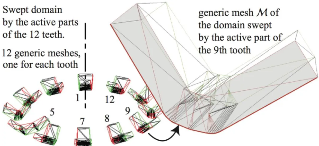
During a time step the motion of the rakes faces, with respect to the volume model of the part, generate a swept domain (Fig. 4). The Boolean intersection between this swept domain and the actual volume domain of the part define that we call a Boolean chip. At each time step this Boolean chip is remove from the volume model of the part. A 2D illustration of this erasing is given in Fig. 4. Rake faces act as matter erasers and not truly chip formation is compute.
Fig. 4: Matter erasing and Boolean chip
On Fig. 4 we use the term of elementary tool T(k ) as each of tooth, or insert, of the tool is partitioned in a set of elementary tools in order to compute more precisely the repartition of the cutting forces applied by each tooth (Fig. 5). And elementary cutting force Fc(k ) is associated to each elementary tool T(k ) immerged inside the part. The value of these cutting forces is deduced from the cutting depth h(k ) and the cutting width b(k ) associated to each T(k ).
For the exhaust manifold a Kienzle cutting force model is used [14], giving:
FT /W , i(k ) K
ib
(k) h(k ) ni with i n,a,g (1)
where n,a,g correspond to a basis local toT(k ): n the outward normal of the rake face (k ) of T(k ), a the direction cutting edge (k )and g a vector belonging to (k ) forming a direct basis with
n and a. FT /W(k ) is the cutting force applied by T(k ) on the workpiece. Its opposite, F
W /T
(k) F
T /W
(k) , is the cutting force applied by the workpiece on the T(k ).
Fig. 5: Partition of the rake faces — Elementary tools
triangular facets. Then the swept domains are represented as B-Rep model using a triangular tesselation. Fig. 6 depicts theses meshes for the tool used to machine the exhaust manifold.
Fig. 6: Mesh of the rake faces associated swept volumes (for a large time step)
The volume model of the part is based on a dexel description ([15],[16]). Dexels can then be seen as parallelepiped domains of section ∆Y×∆X that are defined along the supports in the interval [ZMin, ZMax] (see Fig. 7). The faces of dexels are parallel to the three orthogonal planes defined by (X, Y, Z). A dexel is thus defined by (I, J, ZMin, ZMax) where (I, J) are the integer coordinates of the support. The choice of dexel was imposed to us by the lack of robustness of algorithms dealing with Boolean intersection between tessellations [17].
Fig. 7: The dexels description
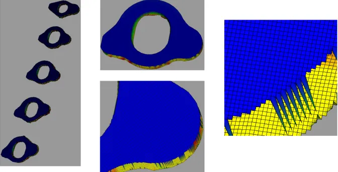
On Fig. 8 is represented the used dexel description for the exhaust manifold. For this example it contains 789 200 dexels (1973 × 400) which correspond to ∆Y=∆X=0.18mm. Some models need more dexels. For example in [18] 31,640,000 dexels were used to describe a large surface of a tube.
Fig. 8: Dexel volumic discretization of the exhaust manifold
At last, the relative velocities between the acting part of the tool and the part are deduced from the motion of the tool and the workpiece (at these contact points) calculated at each time step during the incremental loop described section 3.4, while the motion of the part and the tool are presented section 3.2 and 3.3 respectively.
3.2 Mechanical model of the workpiece
A finite elements model is set up for the workpiece, fixture and clamping in its associated coordinate system RW. Thus this FE dynamical model is build in order to predict vibrations of the part but also deformations induced by clamping. The application of virtual work principle leads to the general system of equation:
W T W W W W W W W q D q K q Q Q M . . . / (2)
where q W is a column containing the degrees of freedom, M W, D W and K W are the mass, damping and stiffness matrices respectively, the column of generalized forces Q T /W comes from the cutting forces FT /W(k ) . Q
Wis the column of generalized forces coming from clamping. In
turning, matrices D W and K W and column Q Wmay include Coriolis and centrifugal acceleration effects [19]. For the exhaust manifold the first eigen frequency deduced from eq. (2) is 1 300 Hz.
Dexel model is connected to the kinematics of this finite element model in order to follow its deformation. This is done by a one to one mapping between a material frame Rm where the dexels carpet and the FE model of the workpiece correspond without any deformation ant the actual configuration RW. This mapping is defined by using the FE kinematics of the part. It
allows to conduct the Boolean intersection between the swept volumes and the actual shape of the workpiece (the dexel model) in the Rm material frame where dexels remain straight. A 2D illustration of the use of during a time stet t is given in Fig. 9.
Fig. 9: beam and spring modeling of the tool
3.3 Mechanical model of the tool
A FE model is also set up for the tool in its associated coordinate system RT. In most situations, a sufficient accuracy is obtained by means of an assembly of beam elements and rigid bodies. In any case the application of virtual work principle leads to the general system of equation:
W T W T T T T T T q D q K q Q Q M . . . / (3)
where qT is a column containing the degrees of freedom of the chosen FE model for the tool, M T, D T and K T are the mass, damping and stiffness matrices respectively, the column of generalized forces Q W /T comes from the cutting forces FW /T(k ) . Matrices D
T and K T may
include Coriolis and centrifugal acceleration effects. If it is the case, Q Wis the column of generalized Coriolis forces. We have not included these non Galilean effects for the exhaust manifold.
For the exhaust manifold, the tool (in fact the system composed of the tool, the spindle and the bearings) is modeled with beams finite elements (45 two nodes linear beam elements with an evolution of the sections as depict on Fig. 10) and springs for the bearings (Fig. 10). We assume that the portion of the tool with the inserts remain rigid (rigid section on Fig. 10). Thus the teeth have a rigid motion defined by the degrees of freedom of the 'master node' of the rigid section.
Fig. 10: beam and spring modeling of the tool
The stiffness of the bearings was adjusted to find the static bending stiffness of the spindle at the axial position of the teeth. The first eigen frequency of the tool is equal to 661 Hz.
3.4 General algorithm
The dynamics is governed by the natural frequencies and mode shapes. As in the work done by Voronov and Kiselev [20], an eigen mode reduction of a FE model is used in our approach for the workpiece and the tool dynamics. This reduces the duration to solve eq. (2) and eq. (3). In the case of the exhaust collector, the associated mode shape matrices of tool and workpiece are assumed constant. At each rotation step of the tool (sample time) the swept volumes for all the elementary tools are found. Intersection of swept volume of tool and current uncut section of the workpiece is found. Iterations are done until removed workpiece material and forces match. After the simulation the results are: the final state of the machined surface (dexels model), the history of the vibrations of the tool and the workpiece, the history of the cutting forces and derived quantities as machining power or spindle torque.
For the case of the exhaust manifold, duration of the simulation goes from 20' to 1 hour depending on the dexel discretization on a laptop computer.
4. RESULTS AND DISCUSSION
To provide quantitative analysis of the machined surfaces under investigation, we focus on the waviness values measured on real parts as well as on computed surface from the simulation results. These measurements have been realized on the central flange among the five flanges constituting the overall machined surface because it is where the part has the greatest compliance (and where major defects are observed). Typical defects on the machined surface are visible on Fig. 11, on the left for a real workpiece and on the right for a virtual workpiece. For this simulation interaction between roughing and finishing is taken into account and so is the clamping effect.
Fig. 11: Geometric defects on the central flange: left real surface, right virtual surface The segments chosen for the waviness evaluation (quadratic waviness W=Wq with a Gaussian filter) are shown in Fig. 12(a). Four machined workpieces have been measured; the results are shown on Fig. 12 (b). The measurement has been realized by means of a waviness tester (MAHR PGK 120 Perthometer), over 18 mm (segments 5 and 6) and 22 mm (segments 1, 2, 3 and 4), with the cut-off wavelength 2.5 mm. For the simulation results, and a post-processing based on the same analysis parameters is carried out.
(a) Waviness measurement locations (b)Measurement results Fig. 12: Waviness measurements
In our modeling approach, we investigated the relative influence of the part flexibility regarding the flexibility of the tool on resulting surface. The influence of damping is also investigated. Our modeling approach includes two stages. Firstly, several simulations are run based on some assumed values, especially with regard to damping and workpiece clamping-induced deformation.
These values are mainly taken from a realistic range based on the practical experience [21] for the assemblies. Secondly, an optimum is sought, in order to obtain simulation results near the measurements.
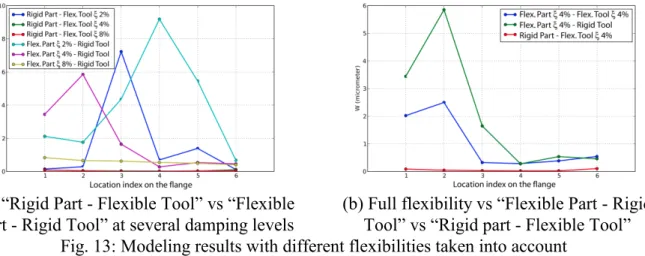
Fig. 13 shows the simulation results for different flexibility types and damping levels. On Fig. 13 (a) one may find the illustration of the fact that the tool compliance alone as well as the workpiece compliance alone can induce similar waviness levels in different zones of the part. Moreover, these levels are relatively high as compared to the measurements. As shown Fig. 13 (b), for the same damping level, accounting for different flexibilities influences induced different defect magnitudes. This plot shows that the tool’s and workpiece’s flexibility influence the resulting waviness and thus none of these flexibilities can be neglected, even, as it is the case in this figure, if the tool seems
widely stiffer than the workpiece. Therefore, following use the full flexibility model.
(a) “Rigid Part - Flexible Tool” vs “Flexible Part - Rigid Tool” at several damping levels
(b) Full flexibility vs “Flexible Part - Rigid Tool” vs “Rigid part - Flexible Tool” Fig. 13: Modeling results with different flexibilities taken into account
The influence of different damping levels, in the part as well as in the tool, on the final surface waviness are shown Fig. 14(a). It is important to remark on this plot that the influence of the damping on the resulting surface defect distribution is nonlinear. In particular, high damping for the tool combined with the low damping of the part (green solid line) yields the lowest level of the waviness defect.
The best-fit configuration of the damping parameters (5% for the part en 8% for the tool, Fig. 14(b)) is then manually found based on the discrepancy with the average measured defect. It may be of interest to notice that this final updated model accounts also for the deformed shape due to the hyperstatical clamping of the workpiece. Nevertheless, the clamping-induced defect is mainly global (overall flatness defect) and its impact is minor for the waviness so it is not presented here.
(a) Partial damping levels variation (b) Best-fit model Fig. 14: Full flexibility model compared to measurement results
5. CONCLUSION
The main objective of this article is the study of the impact of the dynamic behavior of the workpiece and the tool on the result of simulations in term of waviness. We notice that, even if the tool seems
significantly stiffer than the part, to model it as a rigid solid may have an important impact on the results.
The used approach provides a natural way to build a general method allowing to deals with industrial workpieces having complex shapes. Nevertheless, one of the difficulties inherent to this kind of modeling stays damping. Here it was chosen to reproduce at best the experimental results. Up to now, only damping measurements on the real spindle and on the clamped workpiece allow to estimate them.
6. ACKNOWLEDGEMENTS
This research work is supported in by grants from the French designer and manufacturer of machining systems PCI, 42100 Saint Etienne, which is gratefully acknowledged.
7. REFERENCES
1. Andrew C., Tobias S.A., 1961, A critical comparison of two theories of machine tool chatter, Int. J. Machine Tool Design Research, 1:325–35.
2. Altintas Y, Weck M., S.A., 2014, Chatter stability of metal cutting and grinding, CIRP Annals - Manufacturing Technology, 53(2):619–42.
3. Altintas Y, Brecher C, Weck M, Witt S., 2005, Virtual machine tool. CIRP Annals - Manufacturing Technology, 54(2):651–74.
4. Altintas Y., 2012, Manufacturing Automation. Cambridge University Press.
5. Brecher C, Esser M, Witt S., 2009, Interaction of manufacturing process and ma- chine tool. CIRP Annals - Manufacturing Technology, 58:588–607.
6. AltintasY., Montgomery D., Budak E., 1992, Dynamic peripheral milling of flexible structures. Journal of Engineering for Industry, 114:137–45.
7. Corduan N., Costes J.P., Lapujoulade F., Larue A., 2006, Experimental approach of milling stability of thin walled parts, comparison with time domain simulation. In: Proc. 9th CIRP int conf on modelling of machining operations. Bled (Slovenia)., p. 131–7.
8. Assouline S, Beauchesne E, Coffignal G, Lorong P, Marty A., 2002, Numerical simulation of machining at the macroscopic scale: dynamic models of the workpiece, Mécanique et Industries (in French), 3:389–402.
9. Lorong P., Yvonnet J., Coffignal G., Cohen S., 2006, Contribution of computational mechanics in numerical simulation of machining and blanking: state of the art, Archives of Computational Method in Engineering, 13:45–90.
10. Coffignal G., Lorong P., Planchat J., Yaqub S., Larue A., 2007, Virtual machining: a general approach to deal with flexible workpieces, In Proceedings of the 10th CIRP International Workshop On Modeling Of Machining Operations, Reggio Calabria, Italy, August 27-28, p. 477–83.
11. Biermann D., Kersting P., Surmann T., 2010, A general approach to simulating workpiece vibrations during five-axis milling of turbine blades, CIRP Annals - Manufacturing Technology, 59:125–8
12. Lorong P., Coffignal G., Balmes E., Guskov M., Texier A., 2012, Simulation of a finishing operation: Milling of a turbine blade and influence of damping, In ESDA 2012, ASME 2012 11th Biennal Conference on Engineering Systems design and analysis, p. 89–98.
13. Smith S., Tlusty J., 1991, An overview of modeling and simulation of the milling process, Journal of Engineering for Industry, 113:169–75.
14. Kienzle 0., Victor H., 1957, Spezifische schnittkrafte bei der metallbearbeitung. Werkstofftechnik und Machinenbau, 45:224–5.
15. Van Hook T., 1986, Real-time shaded nc milling display, In SIGGRAPH’86., p. 15–20. 16. S.W. Lee, A. Nestler, 2012, Virtual workpiece: Workpiece representation for material removal
process, Int J Adv Manuf Technol, 58:443–63.
17. Stéphanie Cohen-Assouline, 2005, Simulation numérique de l'usinage à l'échelle macroscopique : prise en compte d'une pièce déformable, PhD Thesis.
18. Lorong P., Larue A., Perez-Duarte A., 2011, Dynamic Study of Thin Wall Part Turning, In Proc. of the 13th CIRP Conference on Modeling Machining Operations, Sintra, Portugal. Published in Advanced Materials Research, Vol. 223, pp. 591–599.
19. T. Gmür, 2008, Dynamique des Structures. Analyse modale numérique, Presses Polytechniques et Universitaires Romandes (EPFL).
20. S. A. Voronov and I. A. Kiselev, 2011 , Dynamics of flexible detail milling, Proceedings of the Institution of Mechanical Engineers, Part K: Journal of Multi-body Dynamics, vol. 225, no. 4, pp. 299–309.
21. J.-V. Le Lan, 2007, Etude de méthodes simplifiées pour la simulation de l'usinage à l'échelle macroscopique, PhD Thesis.