Technology researchers and makes it freely available over the web where possible.
This is an author-deposited version published in: https://sam.ensam.eu Handle ID: .http://hdl.handle.net/10985/11995
To cite this version :
Gabriel ABBA, Jean-François ANTOINE, Christophe SAUVEY, Codrut VISA - Design Elements for high speed SRM - Mecatronica - Vol. 3, n°1, p.1-6 - 2004
Any correspondence concerning this service should be sent to the repository Administrator : [email protected]
Design Elements for high speed SRM
Gabriel Abba
†, Member, IEEE, Jean-Francois Antoine
†, Christophe Sauvey
†, Codrut Visa
†‡ Abstract— This paper deals with the study of high speedswitched reluctance motors and their dimensioning. The pre-dimensioning is tackled towards the inductance profile and the torque generation. Then, the power density is assessed in terms of three defined fundamental parameters, each depending on electrical, mechanical and geometrical design of the motor. The mechanical limitations studied are the centrifugal stresses and the vibratory behavior of the motor. A shape optimization of the rotor teeth leans then on a coupled magnetic-mechanic coupled problem, solved with finite elements simulations. After that, mechanic, magnetic and copper losses are given in terms of the rotor external volume so as to assess the weight of each heat source in the global motor heating. Once all the losses are linked to temperature, a criterion to improve the ability to develop a high speed motor is finally proposed.
Index Terms— Switched reluctance motor, high speed spindle,
power density, coupled problems, magnetic losses, thermal limi-tation, motor performances.
I. INTRODUCTION
The technology of part manufacturing by material removal is a key process for many industrial areas of the European Union (automotive, aeronautics, household electrical, lumber industry, ...). The needs to improve the overall performance of machining processes and to achieve technological jumps in order to increase part quality while reducing costs and delays are essential for the European industrial activity.
The decrease of machining costs using higher speeds and controlling tool wear will contribute to maintain or to strengthen industrial competitiveness (and employment also), to increase benefits on concerned parts, and to develop or to access new markets.
The main difficulties in the analysis of machining processes are due to the extreme conditions in which machining is operated, particularly chip removal at high deformation rates, severe friction between tool and material, sudden temperature rises, or vibrations of the machining system. In addition to these, one has to take into account the scale effect of the process (from the micro-scale physics to mesoscale mechanics and macro-scale dynamic behavior of the machining system), and the difficulty to directly measure the characteristic pa-rameters in the cutting zone (forces, rates and velocities, temperatures, pressure, ...).
So, the process optimization from the point of view of de-creasing the manufacturing costs, of inde-creasing tool durability, of controlling the residual stresses of the machined surface, seems to be a difficult objective to achieve alone.
†‡We thank the ”Conseil R´egional de Lorraine” for its help and its financial
support.
G. Abba is with the LGIPM, corresponding author, e-mail : [email protected] J.F. Antoine is with the LGIPM, e-mail : [email protected]
C. Sauvey is with the LGIPM, e-mail : [email protected] C. Visa is with the LGIPM, e-mail : [email protected]
†Laboratoire de G´enie Industriel et de Production M´ecanique (LGIPM),
ENIM - Ile du Saulcy, 57045 METZ Cedex 01, France.
Generally, the quality assurance for a mechanical surface runs through the respect of the functional specifications, relating both to the material metallurgical integrity and the surface quality declined in roughness and form defects. That results by the control or the absence of vibrations during machining and by keeping the cutting pressures and surface temperatures in acceptable values for the part. The reduction of costs is associated to the reduction of production times per part, to the lowest tool wears and then less frequent tool handling, changing and adjustment, to a more rational use of the tools, and to machining where the presence of the lubricant is limited (microlubrication) or is eliminated (dry machining). The reduction of times directly depends on the use of high feed rates and high cutting speeds, on obtaining high chip removal rates, and on the reduction of idle periods.
In the further development, we will focus our attention to the physical limitations of the dimensions and the performances of high speed rotors. We are particularly interested to the 6/2 switched reluctance motor (SRM) structure (figure 5.a). Mechanical limitations are tackled towards centrifugal stresses and vibratory behavior. A way to solve the coupled problem magnetic-mechanic is suggested to increase the SRM power density. Three concurrent loss sources create a thermally coupled problem, dealt with in the last part of this paper, that is thermal limitations.
II. PRE-DIMENSIONING OF THESRM
The pre-dimensioning of a machine makes it possible to quickly know the essential elements of its dimensioning. These elements include dimensional sizes as well as physical sizes such as the phase voltage and the currents or the magnetic fields. The dimensioning of a double saliency SRM requires to define the rotor teeth shape, the teeth widths, the rotor length and the turn number N of stator windings.
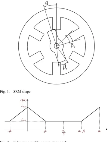
Figure 1 shows a SRM shape. The machine has 3 phases on the stator, Ns = 6 stator teeth and Nr = 2 rotor teeth.
As noted on the figure, βr and βsdefine the rotor and stator
dental angles. The rotor tooth shape allows to determine by finite element resolution the maximum and minimal reluctance of the magnetic circuit. The design of the machine seeks to obtain a profile of inductance as represented on figure 2. In the case of a 6/2 SRM and with βr= βs, we have a maximum
inductance at only one point θ = 0. Moreover, the angle βr is
limited by the problem of field lines dispersion for the position
θ = π/3, which leads to the choice of βrranging between 20o
and 25o.
At first approximation, the minimal and maximum reluc-tance can be connected to dimensions of the machine by the following relations :
Re min= 3 e
π µ0l Ri
Fig. 1. SRM shape
Fig. 2. Inductance profile versus rotor angle
Re max= 3 emax
π µ0l Ri
(2) with emaxand e maximum and minimal thicknesses of
air-gap, µ0 the permeability of the vacuum, l the magnetic part
length of the rotor and Ri the external radius of the rotor.
In the same way, the reluctance of the ferromagnetic parts of the stator and the rotor can be approximated by the following relation :
Rf er= 3 lf er
π µf erµ0l Ri
(3) with lf er the average length of the field lines in iron and
µf er the relative iron permeability.
The reluctances make it possible to deduce the maximum and minimal values of inductances by phase :
Lmax= N 2 Rf er+ Re min = π µ0N2l Ri 3 (e + lf er µf er) (4) Lmin= N 2 Rf er+ Re max = π µ0N2l Ri 3 (emax+µlf erf er) (5) A. Torque generation
The SRM torque is obtained by derivation of the magnetic co-energy stored in the magnetic circuit of the machine. In this motor, the torque is given by the following formula [1]:
Cm=1
2
∂L ∂θ I
2 (6)
(figure 3) and L is the inductance of the phase circuit at a given angular position θ. The inductance variation is obtained by the variation of the air-gap e. The greater this variation is, the stronger the torque can be.
Fig. 3. Power current profile in the phase versus rotor angle
This relation shows that it is interesting to have the max-imum current in the fed phase during all the growth of inductance, meanly on interval [−βr, 0] as shown on figure
3. The effective value of a phase current is thus :
Irms=qIπ βr
(7)
Basically, the electrical circuit of an SRM can be modeled as an R,L circuit. The pulse width modulation converter is used to regulate the current around a maximal value, by chopping volt-age. When a phase becomes excited, the current needs time to rise up to his maximal value. Higher the inductance is, longer the raise time will be. If this time becomes longer than the phase feeding period, the current is not completely established, when commutating, and the average torque decreases.
B. Power density
Under these conditions, the motor power P can be written, in terms of the rotation speed Ω :
P = (Lmax− Lmin) I2Ω
2βr
(8) Copper losses in the stator windings induce a heating of the machine and a thermal problem. The usual solution with this problem consists in limiting the surface current density to the periphery of the stator. The surface current density is defined by :
δL =
6 N I√βr
π√π Ri
(9) Using (4) and (5) in equation (8), and replacing N I by its value resulting from (9), one obtains :
P = p (e, emax) π
2µ
0δL2R2il RiΩ
24 (10)
with
p (e, emax) = emax− e
(e + lf er
µf er)(emax+
lf er
µf er)
(11)
The function p (e, emax) is characteristic of the geometry of
the teeth, of the magnetic field lines in the machine and of the ferromagnetic materials properties. The circumferential rotor
speed is defined by vi= RiΩ. By introducing this value into
the equation (10), one obtains the power density by dividing
P by the rotor volume π R2 il :
P = p (e, emax) π µ0δ 2 Lvi
24 (12)
This formula shows us that the switched reluctance motor power density only depends on three factors p (e, emax), δL
and vi. The p (e, emax) factor depends on the tooth shape and
the characteristics of materials. The surface current density δL
depends on the thermal problems and the cooling process. The circumferential speed of the rotor videpends primarily on the
resistance of materials constituting the rotor.
We are now going to successively approach the dimension-ing step which make it possible to better know these restrictive factors. It is noted right now that for a given power density, the increase of the motor power goes with the increase of its rotor volume.
As the circumferential speed is limited, it is impossible to increase the rotor radius Ri. The power increase thus results in
lengthening the rotor, which introduces an additional problem related to the oscillatory modes, particularly the flexible modes of the rotor.
III. MECHANICAL LIMITATIONS
Mechanical problems implied by high rotational speeds are the greater ones, because they concern the motor reliability and integrity.
A. Centrifugal stresses
The high rotational speed creates high centrifugal tensile stresses in the materials and can cause them to break.
The material of the rotor is defined by its tensile strength
σe and its density ρ.
The maximal stress in the rotor is proportional to the square of its peripheral speed vi and can be written as follows:
σ = K0ρ vi2 (13)
K0 is a coefficient that only depends on the geometrical
parameters of the part that rotates. It can be reduced by an appropriate design of the rotor.
Setting that the stress cannot exceed the tensile stress σe,
the maximal peripheral speed the rotor can bear is then given by: vi max= r σe K0ρ (14) For a given rotational speed, a very careful design of the part will decrease the coefficient K0 so that a greater speed
can be attained.
We also notice clearly that the peripheral speed vi can not
exceed the maximal value supported by the material. This aspect will be further investigated in the section IV-B.
B. Vibratory behavior
The second limitation of a high speed rotor is the vibratory behavior of the rotor. The pulse width modulation principle of the converter generates lots of harmonic excitation forces that cause the rotor to vibrate and touch the stator, with probable destructive effects. Vibrations also create acoustic noise.
For a rotor with a mass mr, supported by two angular
ball bearings with radial stiffness kr, the first rigid vibration
frequency Ω1(cylindrical mode) is given by [2], [3]:
Ω1=
r 2 kr
mr
(15) The radial stiffness of a ball bearing can be written as follows:
kr= K1FP1/3 (16)
K1 accounts for the geometry and materials of the bearing.
The speed limit Ωlimit is then obtained by the following
relationship: Ωlimit ≤ s 2K1FP1/3 mr (17) The inequality must be respected with a security factor for secure vibratory functioning of the rotor. With this formula, one can be tempted to increase the preload FP. However,
if it becomes too big, the thermic problem will outclass the mechanic one.
IV. MAGNETIC-MECHANIC COUPLED PROBLEM In the (11) equation, one other parameter is the p(e, emax)
factor. In order to improve this factor in a high speed switched reluctance motor, one has to perform an optimization which takes into consideration both the electromagnetical and the mechanical aspects. Shape optimization has already been per-formed on switched reluctance motor teeth [4] or synchronous reluctance motors [5]. The particularly high rotation speeds that are aimed (200.000 rpm), make us optimize the motor differently [6].
Otherwise, and as far as we know, the problem of me-chanical behavior of the magnetic sheets is not so commonly studied. In our case, this problem is directly linked to the high speed of the switched reluctance motor. At low speeds, with usual electrotechnical materials, it is not encountered. How-ever, this supplementary problem changes our electromagnetic design problem into a magnetic-mechanic coupled problem.
We have a coupled problem in the sense that we have to solve jointly the electromagnetic and the mechanical problem, with the finite element method. In most cases, the fields of study are depending on time, whereas our problem only has spatial parameters. For the mechanical part of the study, the speed has been taken as constant.
Two rotor shapes had already been studied at the laboratory. The transversal cuts of their electromagnetic parts are shown in figure 4. The first one is a classical structure with a crossing shaft surrounded by a magnetic torque optimized part [7]. The second shape’s electromagnetic part is a parallelepiped inserted and stuck in a guided slot milled in the rotor shaft, made of a resin impregnated phenolic cotton cylinder[8]. The
linkage and the peripheral position of the resisting material assuming to increase the rigidity. The main encountered prob-lem with this solution was the behavior of the glue used to bind the core to the shaft. Even if the rotor contains no winding, its temperature rises during functioning heating the glued interface. Overheating, the latter becomes viscoelastic, its shear strength falls, and the precise positioning of the core in the split is no more insured, when the speed increases.
(a) with crossing axis (b) parallelepiped slotted Fig. 4. Transversal cuts of the two initial electromagnetic rotor shapes
The peripheral speed of the rotor sets its external dimen-sions, and material strength impose the choice of a ferromag-netic material capable to support the centrifugal forces it will sustain. Furthermore, the deformation of the rotor teeth can cause their contact with the stator teeth. The air-gap of the motor has to be consequently adapted.
We chose to proceed by successive approximations in-cluding the analysis of punctual geometries, using two finite element simulation tools, F lux2D for the electromagnetic part and Cosmos/DesignStar for the mechanical design. We had to take into consideration on the whole, the mechanical stresses in the rotor, the high speed current commutations improvement, and the highest average torque optimization.
A. Electromagnetical aspect
From the electromagnetical point of view, we need a rotor design which gives the best average torque with given and constant ampere-turns in the phase. We chose the teeth width, its rotor core joining radius and the teeth side shapes as geometric design parameters. We performed optimization on sharp and rounded teeth (figure 5).
(a) - rounded teeth (b) - sharp teeth Fig. 5. Electromagnetic finite elements simulations for two types of teeth.
We have tried to maximize the average torque of the motor. Its 6/2 structure makes this work easier because the phases
is enough to optimize it on a simple phase. To perform this work, we have been obliged to take into account the following constraints, closely linked to the high speed application:
• In order to limit the commutation problems during the phase current cut, we have to avoid too large an induc-tance variation around the aligned position.
• We know that the phase current rise time is not negligible in comparison with the phase feeding time. So, during this rise time, it is not worth having a large reluctance variation, because it would not be optimally used.
• As the motor is open loop commanded, we have chosen to limit the inductance derivative in terms of the angular position around the rotor angular position of 60 degrees. Otherwise, figure 5 shows the field paths for a rounded teeth (a) and for an sharp one (b), all other parameters remaining constant. We can easily see that they spread exactly in the same way for the both rotor designs, whatever the considered rotor angle. Those finite element simulations prove that the rotor tooth shape has limited influence on the torque wave. The relative position of the rotor corner against the stator corner seems to be more influent. The SRM torque formula TSRM =
i2
2 dLdθ contains implicitly this information. B. Mechanical aspect
(a) - rounded teeth (b) - sharp teeth
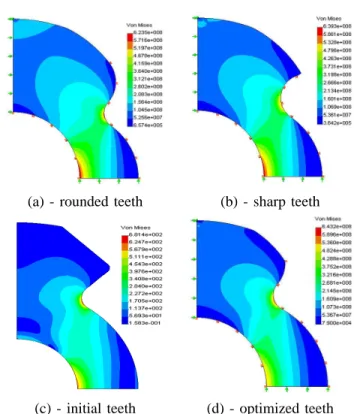
(c) - initial teeth (d) - optimized teeth Fig. 6. Mechanical constraints finite element simulation results.
From the mechanical point of view, the air-gap is problem-atic, because it imposes a minimum space between the inner stator surface and the external rotor teeth surface. The two critical zones we had to consider clearly appears on figure 6. Traction forces are maximal on the shaft border, and the fillet radius at the teeth’s base are more or less stressed in function of the teeth shape.
In all the presented cases, the stress level is smaller than the tensile strength σe of the considered material (metallic
glass : σe = 700M P a). Rounding the teeth shape amounts
to remove slightly stressed material and has few influence on global stress distribution. Otherwise, the small reduction of centrifuged mass reduces the maximal stress from about 2.5%. Moreover, 5.5% reduction were obtained from the initial structure to the final one. The highest stress to tensile strength ratio has passed from more than 97% to less than 92%. The functioning will be more secure.
V. THERMALPROBLEM
The multiple origins of losses that occur in the motor make the thermal limitations more difficult to deal with. The magnetic, mechanical, and copper losses cause the motor temperature to increase. The latter has to be maintained under an appropriate limit to insure its correct and stable functioning. The losses assessment makes it possible to forecast more precisely the SRM power density (12) with the surface current density δL.
All these losses will allow the determination of the operating temperatures in the motor and to choose an appropriate set of parameters.
A. Copper Losses
Using previously explained parameters, copper losses are given by the following relationship :
PJ = 3 R Ief f2 = 3 R (δL2π Ri)2 (18)
Using the lengthening coefficient Kf defined as Kf =
L/(2 Ri) [9], one obtains : PJ= 3 R δL2 π Kf (2πRil) (19) B. Magnetic Losses
Starting with the expression :
PF = a B2fbV (20)
relating magnetic losses PM in the magnetic parts volume
V = γ π R2
i l to the frequency f and the induction B. Defining
the magnetic pressure p = B2/2µ0, magnetic losses are then
given by the following relationship :
PF = a p (2µ0γπ Ri2l) fb (21)
where p is the magnetic pressure.
By substituting the frequency f by its value f = Ω/π and introducing the peripheral speed vi= RiΩ, the magnetic
losses can be written as follows :
PF = a p µ0γ ³ vi π ´b (2 π Ril) (22) C. Mechanical Losses
Mechanical losses for 2 bearings of pitch diameter Dmwith
Z balls of diameter Db, are obtained by [10]:
PM = 2 K3 µ FP C0 ¶1 2 FPDmΩ + 2 K4(ν0Ω) 2 3 D3 mΩ (23)
C0 is the basic static capacity given by C0 = KAZ D2b. KA
is a function of the materials and dimensions of the bearing. One first sets the relations ² = Z Db/(π Dm), ζ = Db/Dm
and η = Dm/Ri, and then one obtains :
PM = 2 σMδ 3 2 MπR2ivi+ σV R4/3i v 5/3 i (24)
where σM = K3KA² ζ η3 is a function of the bearing
dimensions and materials, σV = 2 K4ν2/30 η3 is a coefficient
depending on the only fluid properties and δM = FP/C0 is
the load factor.
D. Thermal limitation
Copper, magnetic and mechanical losses are added to obtain the total power dissipation that occur into the motor. This power loss has to be smaller than the maximal power allowed by the performances of the cooling system. These perfor-mances are represented by the parameter δth(W.m−2.oC−1).
If the cooling surface is S = 2 κ π Ril, then the thermal
equilibrium of the motor is given by :
PJ+ PF+ PM = δth(2 κ π Ril) ∆ T (25)
One finally obtains the following relation :
3 R δ2 L π Kf + a p µ0γ ³ vi π ´b + σMδ3/2M vi 2 Kf + σV v 5/3 i 4 π KfR2/3i = δthκ ∆ T (26)
To maintain the motor to a temperature compatible with a stable and sure functioning, the parameter δLhas to be reduced
in order to keep the global losses under the thermal limit given by the parameter δth. Eq. (12) shows that consequently the
power density of the motor will be reduced. The thermal limi-tation criterion causes the electrical, magnetic and mechanical problems to be coupled.
In this study, the aerodynamic losses due to air-rotor friction were evaluated. However they have to be considered if the peripheral speed increases especially concerning high speed motor. The internal friction of the rotor with air or another fluid is necessary since it allows a better dissipation of heat [11]. This doesn’t concern the present study, since an external cooling was here considered.
VI. SRM PERFORMANCES PREDICTION
The vibratory and thermal modelling allows to study the influence of the preload FP on the performances of the SRM.
These performances are defined in terms of two rotational speed limits, that will be a vibratory and a thermal one.
Preload (N) Rotational speed (rpm) 10−3 10−2 10−1 100 101 102 103 0 0.5 1 1.5 2 2.5 3 3.5 Vibratory limit Thermal limit
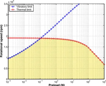
Fig. 7. Speed limitations in terms of the preload FP
Figure 7 presents the vibratory and the thermal limits of the SRM, for a imposed temperature of 40oC on the external
surface of motor. The area is defined by the most demanding of both limiting criteria.
The thermal limit shows that mechanical losses (dependent on preload) are preponderant when the preload exceeds 50N. Under this axial force value, the motor temperature is mainly determined by electromagnetic losses.
The functioning area has to be further investigated in the very high preload area, since it may decrease the bearing’s life.
VII. CONCLUSION
The part manufacturing technology trends towards the use of high speed machining in order to improve its overall performances. Under the circumstances, we tempt to define the limitative elements to the design of high speed switched reluctance motors.
We have first demonstrated that the power density only depends on three fundamental designing factors : the pe-ripheral speed vi, the surface current density δL, and a
function p(e, emax) which depends on the teeth shapes and
the material’s characteristics. Then, we have highlighted the consequences of each parameter on a switched reluctance motor design.
From the mechanical point of view, the centrifugal stresses limit the peripheral speed vi. So, the consequent rotational
speed Ω gives a constraint on the preload FP, useful to solve
the thermal problem.
The magnetic-mechanic coupled problem has been ap-proached to raise the p(e, emax) function. Both
electromag-netical and mechanical aspects have been treated with finite element simulations in order to optimize the rotor shape.
Finally, mechanical, magnetic and copper losses are formu-lated in terms of the rotor surface so as to evaluate their relative weight in the motor temperature rise. Those three sources are concurrent and limited by the motor maximal temperature. The
taken into account in the overall performances prediction. Improving each of the three fundamental factors making the power density will make us able to design more efficient high speed switched reluctance motors in the future.
REFERENCES
[1] T. Miller, Switched reluctance motors and their control, ser. ISBN 0-19-859387-2. Hills-boro, OH: Magna Physics Publishing, and Oxford: Oxford University Press, 1993.
[2] J. D. Hartog, Mechanical Vibrations, 4th ed. Mc Graw-Hill, 1956. [3] J. Ede, Z. Zhu, and D. Howe, “Rotor resonances of high speed permanent
magnet brushless machines,” IEEE transaction on Industry Applications, vol. 38, no. 6, pp. 1542–1548, december 2002.
[4] F. Sahin, H. Ertan, and K. Leblebicioglu, “Optimum geometry for torque ripple minimization of switched reluctance motors,” in Proceedings of International Conference of Electric Motors, ICEM’96, vol. 2. Vigo, Spain: Universidade de Vigo, 10-12 September 1996, pp. 110–115. [5] E. Chiricozzi, G. Conti, F. Parasiliti, and M. Villiani, “Design solutions
to optimize torque ripple in synchronous reluctance motors,” in Proc. of International Conference of Electric Motors, ICEM’96, vol. 2. Vigo, Spain: Universidade de Vigo, 10-12 September 1996, pp. 148–153. [6] J. Antoine, C. Sauvey, C. Visa, and G. Abba, “Optimisation de la forme
d’un rotor de MRV 6/2 pour l’usinage grande vitesse,” in Proceedings of EF’03, vol. CdRom, Gif/Yvette, France, 9-10 D´ecembre 2003. [7] H. Fayard, “Proc´ed´es `a r´eluctance variable pour la conversion d’´energie
´electromagn´etique directe, application `a la grande vitesse,” th`ese, Uni-versit´e de Metz-LGIPM, Ile du Saulcy, F-57000 METZ, 15 Mars 1999. [8] L. Morel, H. Fayard, and R. V. Fos, “A new rotor solution for a high speed machine,” in Proceedings of International Conference of Electric Motors, ICEM’00, vol. 2. Espoo, Finland: Helsinki University of Technology, 28-30 August 2000, pp. 664–668.
[9] D. Matt and J. Llibre, “Performances compar`ees des machines `a aimants et `a reluctance variable. maximisation du couple massique ou volu-mique,” Journal of Physics III, vol. 5, pp. 1621–1641, October 1995. [10] T. Harris, Rolling Bearing Analysis, 4th ed. New York: John Wiley
and sons, 2001.
[11] A. Leontiev, Th´eorie des ´echanges de chaleur et de masse. Moscou: Editions Mir, 1985.