Science Arts & Métiers (SAM)
is an open access repository that collects the work of Arts et Métiers Institute of
Technology researchers and makes it freely available over the web where possible.
This is an author-deposited version published in: https://sam.ensam.eu Handle ID: .http://hdl.handle.net/10985/19441
To cite this version :
Sana CHAABANI, Iñigo RODRIGUEZ, Mikel CUESTA, Yessine AYED, Pedro José ARRAZOLA, Guénaël GERMAIN - Tool wear and cutting forces when machining inconel 718 under cryogenic conditions: Liquid nitrogen and carbon dioxide - In: Proceedings of the 22nd International Esaform Conference On Material Forming: ESAFORM 2019, Espagne, 2019-05-09 - 22nd International ESAFORM Conference on Material Forming, ESAFORM 2019 - 2019
Any correspondence concerning this service should be sent to the repository Administrator : archiveouverte@ensam.eu
Tool Wear And Cutting Forces When Machining Inconel 718
Under Cryogenic Conditions: Liquid Nitrogen and Carbon
Dioxide
S. Chaabani
1,2,a), I. Rodriguez
1, M. Cuesta
1, Y. Ayed
2, P.J. Arrazola
1and G.
Germain
21Faculty of Engineering, Mondragon Unibertsiatea, 20500 Mondragon, Spain. 2Arts et Metiers, LAMPA, 2 boulevard du Ronceray, 49035 Angers, France.
a)Corresponding author: schaabani@mondragon.edu
Abstract. Nickel-based superalloys are widely exploited in turbojets components which are subjected to intense thermal and mechanical loadings during their operation. In fact, they exhibit excellent mechanical properties over a wide range of temperature and high corrosion and creep resistance. However, these materials induce several problems related to the shaping by machining due to essentially high heat resistance, high hardening tendency, high chemical affinity with tool material and low thermal conductivity leading to very high temperature in the cutting zone. In this context, assisted machining processes aim to improve the productivity of certain materials that are difficult to cut. Indeed, in order to keep the tool cold, it has been proposed to use cryogenic fluids (liquid nitrogen LN2and carbon dioxide CO2as coolant for effectively reducing temperatures since their vaporization temperatures
are equal to -196◦
C and -75◦
C respectively. In this context, previous researches have focused on the study of the efficiency of this technique with respect to the machinability of several materials such as titanium alloys and nickel-based alloys. It has been shown that the tool life is improved when machining titanium alloys, unlike nickel-based alloys. For this reason, this paper is devoted to a comparison between two cryogenic fluids (LN2and CO2) with regard to their effects on tool life when machining Inconel 718
considering as a reference the conventional lubrication. Keywords: Machining, Inconel 718, Cryogenic, Tool wear.
INTRODUCTION
Nickel superalloys reveal excellent mechanical properties at high temperature, high corrosion and creep resistance. Consequently, nickel based alloys are largely employed in the aeronautic applications. However, such alloys are dif-ficult to cut materials due to many reasons such as the strain hardening while machining process [1]. In addition, these alloys present high chemical affinity with most of tool material leading to rapid wear of the tool by adhesion and diffusion mechanisms [2, 3]. Moreover, the nickel based alloys exhibit very low thermal conductivity inducing high cutting temperature at the cutting zone [4, 5]. For these reasons, to maintain the tool cold as possible and thus to decelerate tool wear evolution, it is relevant to use assisted machining process for instance, high pressure water jet [6, 7] as well as cryogenic machining process [8, 9]. In addition, cryogenic process provides an ecological and safe alternative motivating to industrial applications. In this context, previous works have figured out the effect of cryo-genic machining on tool wear when machining hard to cut materials either in the case of using liquid nitrogen LN2
or carbon dioxide CO2. Indeed, Ayed et al [10] have reported the effect of cryogenic cooling on tool wear, especially
tool flank wear. Following the tests carried out during the machining of the Ti64 alloy, they have figured out that the evolution of the tool flank wear, is less important in the cryogenic conditions using the liquid nitrogen compared with dry and conventional cooling conditions. Indeed, under dry and conventional conditions, the tool life is lower than 2.5 min and 6 min respectively. In contrast, after 15 min of machining, the tool flank wear does not exceed 0.2 mm under cryogenic conditions when the liquid nitrogen was maintained at high flow rate and high pressure. They have explained this by the fact that the nitrogen jet contributes to lowering the cutting temperature and subsequently to control relatively the wear mechanisms [11].
Thereafter, Kaynak [12] has investigated the performance of Inconel 718 under cryogenic assistance machining by comparing it with dry and MQL machining conditions. Indeed, during the tests, he chose two nozzles to throw the liquid nitrogen at the cutting face and the flank of the tool. The results obtained indicate a good agreement with the re-sults cited above with respect to the reduction in the tool flank wear by comparing the other machining modes namely dry and MQL machining conditions. In fact, the largest measure has been identified in the case of dry machining. However, the MQL approach provided values slightly close to those obtained in cryogenic machining up to 2.5 min and then the tool flank wear increases rapidly to show the same trend as the dry condition.
Recently, Iturbe et al [1] have conducted an extensive research to estimate the extent to which conventional lubrication could be replaced by cryogenic fluid (LN2). To do this, they took over the same configurations exploited
by Kaynak (the work material Inconel 718, the cutting parameters, the geometry of the tool). Indeed, the tests were carried out under two conditions namely conventional machining and machining associating MQL and cryogenic fluid. As a result, the findings revealed that the tool life presents a significant difference between conventional lubrication and cryogenic conditions. In the case of conventional machining, the life of the tool exceeds 20 min and shows a homogeneous evolution. However, in the other case (MQL+ cryogenic), the evolution of the tool wear occurs quickly and the standard criterion of the life of the tool is reached for shorter times (less than 7 min). This is likely due to the fact that the machined material Inconel 718 has a tendency to hardening excessively under the effect of cryogenic temperatures. Thereby, generating the degradation of the tool and consequently the reduction of its life.
Few researches have studied the effect of cryogenic machining using carbon dioxide CO2 as a cutting fluid
performed on several workpiece materials for instance hardened steel, Ti64 and Inconel 718 [13, 14]. Indeed, it has been reported that cryogenic machining using the CO2 showed better performance in terms of tool life or cutting
length in comparison with the LN2cryogenic condition, dry and traditional lubrication. For instance, Jerold et al [15]
have figured out the effect of cryogenic fluids (LN2and CO2) on tool wear considering as a reference the conventional
lubrication. Subsequently, Bagherzadeh et al [16] have carried out an extensive study focusing on CO2 cryogenic
cooling approach using different configurations. In fact, during the experiments, they have employed four cooling strategies consisting in: cooling the tool rake face using the CO2 cryogenic fluid, cooling the rake face using CO2
and the flank face using MQL, combining the CO2fluid and the MQL to cool the tool rake face (CMQL) and using a
modified nozzle to cool simultaneously rake and flank faces using the CO2cutting fluid. The following table highlights
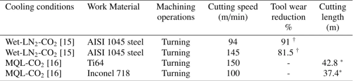
a summary of the results obtained in the previous works carried out when machining several materials under cryogenic conditions focusing on the CO2performance compared with dry, MQL or wet conditions (Table 1).
TABLE 1. Summary of the previous studies showing the effect of the CO2performance compared to different
cooling methods
Cooling conditions Work Material Machining Cutting speed Tool wear Cutting operations (m/min) reduction length
% (m)
Wet-LN2-CO2[15] AISI 1045 steel Turning 94 91†
Wet-LN2-CO2[15] AISI 1045 steel Turning 145 81.5†
MQL-CO2[16] Ti64 Turning 150 - 42.8∗
MQL-CO2[16] Inconel 718 Turning 100 - 37.4∗
∗ Cutting length obtained in CO
2cooling condition. † Reduction of tool wear obtained in CO
2compared to wet condition.
So far, according to the review literature, there is no study that has focused on the comparison between the cryogenic fluids performance namely LN2and CO2when machining Inconel 718 using the same cutting parameters
in order to identify the influence of each cryogenic fluid on Inconel 718 machinability.
This paper is dedicated to examine the effect of the latter cryogenic fluids on tool life when machining In-conel 718 considering as a reference the conventional lubrication. Therefore, the experimental methodology is detailed followed by a comparison between the cryogenic configurations performance and traditional lubrication in terms of tool life. Cutting forces are also included.
Experimental methodology
Experimental set-up
Machining trials were carried out under conventional coolant and cryogenic cutting fluids using liquid nitrogen LN2
and carbon dioxide CO2. The trials were performed using the same test configuration on a horizontal turning CNC
lathe Danumeric 2. Turning tests with the conventional lubrication were conducted cooling the cutting zone with the HOCUT 3380 fluid. As for the cryogenic tests using LN2as a coolant, the cryogenic system is composed of the phase
separator, the cryogenic control and the liquid nitrogen bottle mounted on the CNC lathe. LN2spray was activated
before beginning the machining process in order to achieve stable outlet condition. With respect to the CO2system, it
is composed of a bottle of CO2maintained at high pressure equal to 57 bars at room temperature (Fig 1).
FIGURE 1. Experimental cryogenic systems: LN2and CO2
Experimental procedure
Longitudinal turning experiments were conducted in finishing operations on forged Inconel 718 bar using the same cutting parameters and the same cutting tool as Iturbe [1], that are a cutting speed of 70 m/min, a feed per revolution of 0.2 mm/rev and a depth of cut of 0.2 mm. However, three cooling ways were employed: LN2(the delivery position
and the diameter of the nozzle have been changed compared to [1]), CO2 and conventional cooling. CVD coated
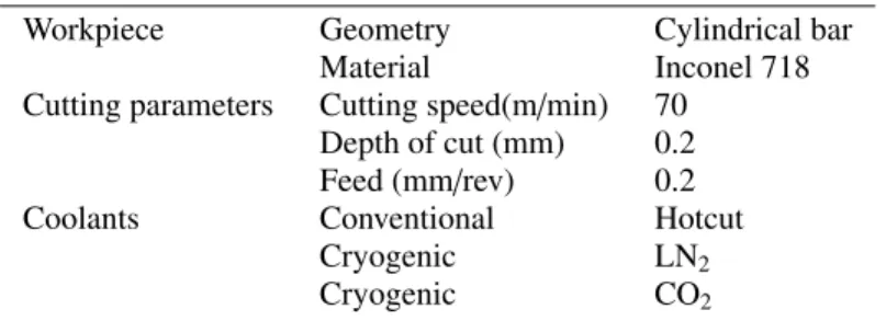
carbide inserts from Mitsubishi supplier (DNMG 150612-MS US905) having a tool nose radius of 1.2 mm were exploited in the trials. Table 2 sets out the machining conditions:
TABLE 2. Working conditions
Workpiece Geometry Cylindrical bar
Material Inconel 718
Cutting parameters Cutting speed(m/min) 70 Depth of cut (mm) 0.2 Feed (mm/rev) 0.2
Coolants Conventional Hotcut
Cryogenic LN2
Cryogenic CO2
The experimental tests were conducted until reaching the target machining time (15 min) or when the maximum tool life defined as Vbmax= 0.3 mm was reached according to the standard 3685:1993.
Each experiment has been carried out two times using the same cutting tool edge under each cooling condition and the average values have been exploited for the analysis. Tool flank wear measurements have been recorded using a LEICA Z16 APO macroscope after each cutting test. Furthermore, the cutting forces were recorded using Kistler 9121 dynamometer.
Results and discussions
Tool wear
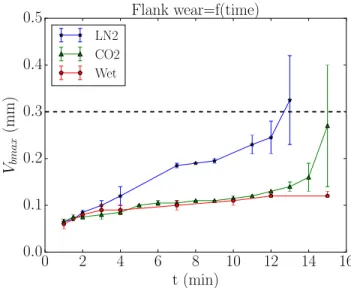
Tool flank wear evolution was recorded during the longitudinal turning trials in all cooling strategies (conventional and cryogenic conditions). The experiments were stopped at a machining time of 15 minutes in wet condition even if the maximum flank wear did not exceed the criterion of Vbmax= 0.3 mm. Nevertheless, under cryogenic conditions, the
experiments were stopped when the tool flank wear achieved the criterion value. As illustrated in Fig 2, results showed that the tool life in conventional condition is the longest duration achieved. Indeed, the tool flank wear does not exceed 0.12 mm after 15 minutes of machining in wet condition. Regard the CO2cooling condition, the same tendency of tool
wear evolution has been observed until reaching 12 min of machining. However, after 12 min, tool flank wear increases notably to exceed the criterion at 15 min. As for LN2cryogenic condition, this parameter increased rapidly from the
first 2 minutes of machining leading to shorter tool life. Additionally, under LN2cryogenic condition, the chipping of
the cutting tool was drastically pronounced compared to the conventional lubrication. Furthermore, it should be noted that the tool wear evolution under both cryogenic conditions is quite repeatable at the beginning of the cutting process. However, a notable variability occurred at 11 min and 13 min respectively under LN2and CO2 cooling approaches
when the tool flank wear evolved significantly. Overall, under conventional coolant environment, a homogeneous tool flank wear evolution was observed even after longer machining times showing a good repeatability. Nevertheless, in LN2cryogenic machining condition, wear peaks were recorded from the beginning of the turning process, revealing
that the cutting process is not performed homogeneously whereas this parameter reveals a steady and slow evolution under CO2cryogenic condition except the last minutes of machining as shown in Fig 3.
0
2
4
6
8
10
12
14
16
t (min)
0.0
0.1
0.2
0.3
0.4
0.5
V
bmax(mm)
Flank wear=f(time)
LN2 CO2 WetFIGURE 2. Tool flank wear evolution in different cooling conditions: Wet, LN2and CO2.
FIGURE 3. Comparison of tool flank wear evolution in different cooling conditions: a) Wet, b) LN2and c) CO2after 10 min of
Cutting forces
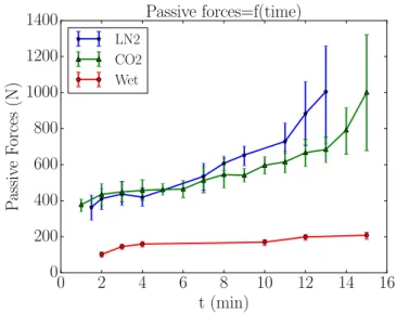
The cutting forces are crucial factors that indicate the power consumption in the machining process. Actually, the cutting forces components are strongly dependent on several parameters for instance the workpiece properties, the cutting tool material and geometry as well as the coolant strategy. In this work, one is interested to figure out the tendency of cutting forces components when machining Inconel 718 under wet and cryogenic conditions (LN2 and
CO2) that reveal the state of tool wear. Indeed, the cutting, the feed and the passive forces are significantly higher
under cryogenic cooling environments than in the case of conventional lubrication (Fig 4 and Fig 5).
0
2
4
6
8
10
12
14
16
t (min)
0
50
100
150
200
250
300
350
400
Cutting
F
orces
(N)
Cutting forces=f(time)
LN2 CO2 Wet0
2
4
6
8
10
12
14
16
t (min)
0
50
100
150
200
250
300
350
400
F
eed
F
orces
(N)
Feed forces=f(time)
LN2 CO2 WetFIGURE 4. Comparison between cutting forces components evolution in different cooling conditions: Wet, LN2and CO2: Cutting
forces (left) and Feed forces (right).
0
2
4
6
8
10
12
14
16
t (min)
0
200
400
600
800
1000
1200
1400
P
assiv
e
F
orces
(N)
Passive forces=f(time)
LN2 CO2 WetFIGURE 5. Comparison between passive forces evolution in different cooling conditions: Wet, LN2and CO2.
Actually, the cryogenic fluids namely LN2 and CO2 exhibit very low temperature during the machining tests
inducing likely higher flow stresses of the workpiece material even before cutting. Probably, this is could be because of a notable cooling effect of the cryogenic fluids preventing the material softening. Consequently, the cutting forces components increase drastically. Focusing on the tendency of the three components of the cutting forces obtained
in conventional condition that showed lower values when machining Inconel 718 in comparison with LN2 and CO2
cryogenic fluids. In fact, the maximum value of cutting forces that has been recorded in conventional condition is 180 N while in LN2and CO2cooling conditions, this parameter has exceeded 300 N and 250 N respectively. Moreover,
the feed forces reveal the same tendency where the maximum values are obtained under LN2cryogenic conditions. In
contrast, the passive forces showed the highest values measured in all cooling approaches compared to the cutting and feed forces. Results revealed huge values obtained in both cryogenic conditions compared to conventional lubrication. Additionally, it should be noted the strong correlation between the tendency of passive forces and the evolution of tool flank wear. Effectively, one can figure out the trends of the passive forces with tool flank wear state at different machining times under all cooling conditions namely the conventional and the cryogenic cutting fluids. As obviously illustrated in all figures, as the machining time increases, the tool flank wear increased as well. Thereby, passive forces increased relatively to the coolant condition. In particular, passive forces evolution is steady and slow in wet condition unlike the cryogenic conditions where the passive forces rise quite notably. This phenomenon is more pronounced in LN2cooling environment than in CO2condition. This fact may be due to the rapid tool flank wear evolution in LN2
cryogenic condition indicating that the passive forces are the most sensitive to tool flank wear.
Conclusion
In this paper, a literature review was reported concerning the study of the poor machinability of nickel-based super-alloy Inconel 718. Then, the machining performance of the work material was identified by mentioning the major research that have focused on the cryogenic cooling effect on tool wear when machining Inconel 718.
Subsequently, machining trials using three different cooling conditions namely conventional and LN2and CO2
cryo-genic conditions have been presented. The experimental results showed the good performance during machining of conventional coolant in terms of tool life reaching 15 min knowing that the flank wear does not achieve the criterion. In contrast, the LN2condition indicates shorter tool life revealing a rapid and non homogeneous tool flank wear. With
respect to the CO2cooling condition, the tool flank wear showed slight difference compared to the conventional
lubri-cation performance only at longer machining time.
Additionally, the cutting forces components showed higher value in the case of cryogenic environments than in con-ventional condition due to the significant cooling effect.
Finally, for enhancement purposes, one is extremely interested in understanding the main tool wear mechanisms under the whole cooling strategies. For this reason, extensive analysis will be conducted using SEM technique as well as the surface integrity investigation (microstructure damage and residual stresses).
REFERENCES
[1] A. Iturbe, E. Hormaetxe, A. Garay, and P. Arrazola, Procedia CIRP 45, 67–70 (2016).
[2] G. R. Thellaputta, P. S. Chandra, and C. Rao, Materials Today: Proceedings 4, 3712 – 3721 (2017). [3] M. Imran, P. T. Mativenga, A. Gholinia, and P. J. Withers, International Journal of Machine Tools and
Manufacture 76, 49–60 (2014).
[4] E. Ezugwu, Z. Wang, and A. Machado, Journal of Materials Processing Technology 86, 1–16 (1999). [5] D. Dudzinski and A. Molinari, International Journal of Mechanical Sciences 39, 369–389 (1997). [6] Y. Ayed, G. Germain, A. Ammar, and B. Furet, Wear 305, 228–237 (2013).
[7] T. B. Bouchnak, “Etude du comportement en sollicitations extrłmes et de l’usinabilit d’un nouvel alliage de titane aronautique : le ti555-3,” Ph.D. thesis, Ecole Nationale Suprieure d’Arts et Mtiers-ParisTech 2010. [8] F. Pusavec, A. Deshpande, S. Yang, R. M’Saoubi, J. Kopac, O. W. Dillon, and I. Jawahir, Journal of Cleaner
Production 81, 255– 269 (2014).
[9] D. Umbrello, F. Micari, and I. Jawahir, CIRP Annals 61, 103–106 (2012).
[10] Y. Ayed, G. Germain, M. Pubill, P. Kowalewski, and D. Locufier, The International Journal of Advanced Manufacturing Technology 93, 1199–1206 (2017).
[11] M. Dhananchezian and M. P. Kumar, Cryogenics 51, 34–40 (2011).
[12] Y. Kaynak, The International Journal of Advanced Manufacturing Technology 72, 919–933 (2014). [13] N. Patil, A. Asem, R. Pawade, D. Thakur, and P. Brahmankar, Procedia CIRP 24, 86– 91 (2014). [14] S. Cordes, F. Hbner, and T. Schaarschmidt, Procedia CIRP 14, 401– 405 (2014).
[15] B. D. Jerold and M. P. Kumar, Cryogenics 52, 569 – 574 (2012).