Science Arts & Métiers (SAM)
is an open access repository that collects the work of Arts et Métiers Institute of Technology researchers and makes it freely available over the web where possible.
This is an author-deposited version published in: https://sam.ensam.eu Handle ID: .http://hdl.handle.net/10985/18800
To cite this version :
Nicolas CONIGLIO, C. E. CROSS - Effect of weld travel speed on solidification cracking behavior. Part 3: modeling - The International Journal of Advanced Manufacturing Technology - Vol. 107, n°11-12, p.5039-5051 - 2020
Any correspondence concerning this service should be sent to the repository Administrator : [email protected]
1
Effect of Weld Travel Speed on
Solidification Cracking Behavior. Part 3:
Modeling
N. Coniglio a and C.E. Cross b
a Laboratory of Mechanics, Surface and Materials Processing (MSMP-EA7350), 2 cours des Arts et Métiers, 13617 Aix-en-Provence – France. Email : [email protected]. Phone : 0033 4 4293 8183.
b Los Alamos National Laboratory (LANL), Los Alamos, NM (United States)
A. ABSTRACT
Solidification cracking is a weld defect common to certain susceptible alloys rendering many of them unweldable. It forms and grows continuously behind a moving weld pool within the two-phase mushy zone and involves a complex interaction between thermal, metallurgical and mechanical factors. Research has demonstrated the ability to minimize solidification cracking occurrence by using appropriate welding parameters. Despite decade’s long efforts to investigate weld solidification cracking, there remains a lack of understanding regarding the particular effect of travel speed. While the use of the fastest welding speed is usually recommended, this rule has not always been confirmed on site. Varying welding speed has many consequences both on stress cells surrounding the weld pool, grain structure, and mushy zone extent. Experimental data and models are compiled to highlight the importance of welding speed on solidification cracking. This review is partitioned into three parts: Part I focuses on the effects of welding speed on weld metal characteristics, Part II reviews the data of the literature to discuss the importance of selecting properly the metrics, and Part III details the different methods to model the effect of welding speed on solidification cracking occurrence.
Keywords: solidification cracking; welding; welding speed; crack initiation; crack growth.
B. NOMENCLATURE
fs Solid fraction2
t Time
vL Liquid flow velocity
vT Liquidus isotherm velocity
x Distance from weld center CSZ Crack Susceptible Zone
G Temperature gradient
HCS Hot Cracking Susceptibility
K Thermal conductivity
SPV Maximum volumetric flow rate
SRG Maximum volumetric solidification shrinkage
T Temperature TL Liquidus temperature TS Solidus temperature Thermal diffusivity Solidification shrinkage 𝛿 Transverse displacement 𝛿̇ Rate of transverse displacement
𝜀 Strain
𝜀̇ Strain rate
Viscosity
2 Secondary dendrite arm spacing
C. INTRODUCTION
Solidification cracking is a commonly encountered defect during welding, especially in high-sulfur steels, austenitic steels, and aluminum alloys. Solidification cracks form due to a complex interplay of mechanical, thermal, and metallurgical factors. Their formation is strongly dependent on both material composition and welding parameters. To increase productivity, fabricators aim at reducing manufacturing time by increasing welding speed. This commonly implies using laser and electron-beam welding processes that involve welding speeds (101-102 mm.s-1) faster than commonly encountered in arc welding processes (100-101 mm.s-1). However, while the use of fastest travel speeds in arc welding to avoid solidification cracking has been commonly accepted, it seems not to always apply for the faster speeds encountered during beam welding that can lead to numerous weld bead defects [1,2] including solidification cracking itself.
Solidification cracking, described by Campbell as “an uniaxial tensile failure in weak materials” [3], appears at the solidification end inside a mushy zone that is subjected to tensile strains. The microstructure forms in the solidification zone, referred to as the mushy zone, located at the rear of the melting zone and bordered by two isothermal surfaces corresponding to liquidus and solidus temperatures. The semi-solid in the mushy zone has little ductility in the terminal stage of solidification, when the liquid fraction is no longer high enough for grains to move around and rearrange in order to accommodate tensile strains. When liquid feeding cannot adequately compensate solidification shrinkage and thermal contraction of the mushy zone, solidification cracking occurs along grain boundaries.
3 Numerous stress-based, strain-based, and strain rate-based models have been proposed to provide insights into cracking mechanisms, as indicated in reviews on the subject [4–10][11]. Stress-based models assume cracking to occur when tensile stresses exceed the semi-solid strength. Strain-based models associate cracking with tensile strains exceeding the ductility of grain boundary liquid films. Strain rate-based models take cracking as the inability of liquid to feed the gaps opening at the tensile strain rate velocity. Therefore, solidification cracking models are based on either static (strength, ductility) or dynamic (liquid feeding ability) properties.
Solidification cracking has been modeled in terms of initiation and growth. Some calculations have shown that the initiation site may be present as a pre-existing defect, leading to the thought that only growth controls the crack formation. Therefore, welding speed may be important in so far as it avoids maintaining crack growth during the welding process.
Most of the research is aimed at elucidating the metallurgical processes involved in solidification crack initiation and growth. Nevertheless, our ability to predict solidification cracking needs to better understand welding stress and strain patterns in addition to the metallurgical processes. Reviews of solidification cracking theories [4–10][12] highlight that both metallurgical and mechanical factors must be present for solidification crack formation. This is particularly true for modeling travel speed effect on solidification cracking as faster welding speed changes solidification rate, elongates thermal fields, modifies grain structure, and influences thermal strain cells surrounding the mushy zone.
Little research work has been reported in the literature on the relationship between travel speed and solidification cracking. This review, part III of the series, focuses on the models developed to simulate the effect of welding speed on solidification cracking behavior. The present work is presented in two sections: modeling the solidification cracking mechanics and modeling the effect of welding speed on solidification cracking initiation and growth.
D. Solidification cracking criteria
Solidification cracking should be examined in terms of initiation and growth. Such a distinction is of importance since the mechanisms involved and conditions required to initiate a crack can differ from the ones to grow a crack. The initiation is associated with the formation of an initiation site, such as a defect, from which a crack may grow under specific conditions. The nature of the initiation site and the path of the growth are part of the interrogations that solidification cracking models must answer.
4
I. Crack initiation
While some cracking models consider the maximum stress a liquid film can sustain [13–15][16] most assume that fracture in the mushy zone is strain limited [17–19]. Arguing that a large solidification range permits a large buildup of strain and a greater likelihood to crack [20,21], it has been demonstrated that cracking will occur if the accumulated strain exceeds a ductility limit represented by characteristic ductility curves established for specific alloys.
Limited ductility models associate solidification cracking susceptibility to the length of the CSZ. The different strain theories developed [17,20,22–30] initially applied to castings [31–33][34] explain solidification cracking in terms of the time rate of extension developed in the liquid films (Figure 1) and have been compared for castings [35]. The rate of extension per unit of time is a function of the thermal and mechanical stresses.
Figure 1 Schematic of strain theories associated with solidification cracking.
Ductility-based models have recognized that strain rate is also an important factor, but only insofar as it serves to determine how much strain can be accumulated during the time of solidification [18,19]. However, recent developments suggest that the strain rate may actually play a more direct role in the liquid fracture mechanism [36,37]. These liquid feeding models associate longer mushy zone with difficult liquid feeding ability and high susceptibility to solidification cracking. The Hagen–Poiseuille law states that the volumetric flow rate of a liquid through a channel decreases with increasing channel length and with decreasing channel opening due to the resistance to flow caused by the viscosity of the liquid.
The hot tearing criterion proposed by Clyne and Davis [38] is based on the assumption that, in the last stage of freezing, liquid feeding is difficult in order to accommodate by mass feeding the strain applied during this stage. This cracking susceptibility coefficient referred to as Hot Cracking Susceptibility (HCS) is defined by the vulnerable time period tV during which solidification cracking
may develop, and the time tR available for stress-relief process where mass feeding and liquid
feeding occurs [38]:
𝐻𝐶𝑆 =𝑡𝑉 𝑡𝑅=
𝑡99−𝑡90
5 , where 𝑡99, 𝑡90and 𝑡40 are the times when fs=0.99, fs=0.90 and fs=0.40, respectively. Similar criteria were developed using different critical solid fractions simulating feeding [39–41][42] and later associating the solidification crack initiation to the mushy zone decohesion [43].
The prominent Rappaz-Drezet-Gremaud (RGD) model [37,44,45][46,47], founded on physical bases, considers both uniaxial tensile deformation and shrinkage feeding and has been applied to aluminum welding [45]. The maximum deformation rate sustainable by the mushy zone before crack nucleation at the root of dendrites was determined by:
∫ (∫ 𝑓𝑆(1−𝑓𝑆𝜀̇𝑑𝑇)(𝑓)3𝑆)2 𝑇𝐿 𝑇𝑆 𝑑𝑇 = 𝜆22 180 𝐺 (1+𝛽)𝜇(𝑝𝑚− 𝑝𝑐) − 𝜗𝑇 𝛽 1+𝛽∫ (𝑓𝑆)2 (1−𝑓𝑆)2 𝑇𝐿 𝑇𝑆 𝑑𝑇 (Eq. 2)
, where T is temperature, 𝑇𝐿 liquidus temperature, 𝑇𝑆 solidus temperature, 𝑓𝑆 solid fraction, 𝜀̇ strain rate normal to growth direction, 𝜆2 secondary dendrite arm spacing, G temperature gradient in growth direction, 𝛽 solidification shrinkage, 𝜇 liquid viscosity, 𝑝𝑚 metallostatic pressure, 𝑝𝑐 cavitation pressure, and 𝜗𝑇 liquidus isotherm velocity. The welding speed effect is implicitly related to the liquidus isotherm velocity 𝜗𝑇. Faster speeds lead to greater 𝜗𝑇 values and smaller 𝜆2 values. Pressure drop magnitudes (101-102 kPa) are not always sufficient for crack nucleation (liquid fracture requiring 105-107 kPa) by cavitation [4]. Combined with thermal fields calculations, the RDG has been proven useful in determining the solidification cracking susceptibility of AA6016 when laser-beam welded [48]. This model is implemented into other models to calculate the pressure drop along the feeding channel and therefore the driving force for crack growth from a pre-existing pore using mass-balance [36,49,50] or pressure-balance [51,52] conditions.
The susceptibility of an alloy to solidification cracking was associated with the ratio of dT/d(fs1/2) and dT/d(fs1/3) for columnar and equiaxed structures, respectively [10], with T temperature and fs solid fraction. Solidification cracking is formed when:
{𝑑𝜀𝑙𝑜𝑐𝑎𝑙 𝑑𝑡 > √1 − 𝛽 𝑑 √𝑓𝑠 𝑑𝑇 𝑑𝑇 𝑑𝑡+ 𝑑 𝑑𝑧[(1 − √1 − 𝛽 √𝑓𝑠)𝑣𝑧]} √𝑓 𝑠→1 (Eq. 3) The criterion is in the same category as the Feurer criterion [53], which associates cracking to the condition “Rate of volume increase > Rate of volumetric liquid flow”. Hence, high absolute values of dT/d(fs1/2) metrics near the end of solidification (i.e. fs close to 1) are related to long channels
that are hard to feed and are crack susceptible [10,54]. This criterion has been successfully applied to a weldability investigation and especially in ranking aluminum alloys [55,56] and magnesium alloys [57] in terms of solidification cracking susceptibility.
Even though some criteria have been based on equilibrium diagrams [38,39,58], welding implies non-equilibrium and complex back-diffusion conditions. The back-diffusion effect was
6 investigated on the undercooling value for grain boundary coalescence [59]. Solid diffusion coefficients affect the final coalescence temperature. While standard backdiffusion models are efficient for neutral grain boundary conditions, repulsive conditions move for fast elemental diffusion (Lever rule) the final freeze temperature to lower values, with an undercooling achievable as high as 60 K (Figure 2) [59].
Figure 2 Influence of backdiffusion on solidification path and coalescence of a binary alloy for two type of
interfaces: attractive (𝛾𝑔𝑏 = 0) and repulsive (𝛾𝑔𝑏= 3𝛾𝑠𝑙) [59]
Misorientations of grain boundaries have been numerically proven to delay coherency and subsequently affect solidification crack formation [45,60]. Figure 3 shows the portion of coalesced grain boundary along two grain boundaries for attractive and repulsive conditions [59]. Bridging starts at higher temperatures for attractive boundaries with a difference of almost 20K [59]. Supposing a cooling rate in welds of 100 K∙s-1, this represents up to 1 to 10 mm longer mushy zone for welding speeds of 5 and 50 mm∙s-1, respectively. Whether welding speed can affect these coalescence behaviors by changing surface tensions of growing grains remains unresolved.
Figure 3 Calculated fraction of grain boundary in a binary alloy for two type of interfaces: attractive (𝛾𝑔𝑏= 0)
and repulsive (𝛾𝑔𝑏 = 3𝛾𝑠𝑙) [59]
These criteria can successfully compare alloys and estimate the inherent propensity of a solidifying microstructure to solidification cracking. The physical basis is that deep narrow throats are difficult to feed. One question remains about the range of solid fraction to consider for
7 cracking evaluation. In fact, the overall temperature range for solidification may not be important but rather only what happens between the coherency and the rigidity temperatures. The point at which the semisolid is strong enough to resist the tensile strains without liquid feeding is ill-defined.
II. Crack growth
It may not be initiation but growth that is critical for solidification cracking. Indeed, some works have associated initiation to cavitation induced by pressure drop in castings [37], but the pressure drops measured in welding (102 kPa) are too small for cavitation (104-105 kPa) if the partial pressure of the dissolved gases is low [36]. For example, in-situ measurements in casting estimate a pressure drop of 22 kPa when observing solidification crack initiation in Al-0.5 wt.%Cu [61]. Therefore pre-existing nuclei were suggested to be present prior to solidification [36] such as oxide bifilms [62]. With this point of view, the evolution of a pre-existing initiation site into a growing crack is modeled.
There is also an awareness that solidification cracking is not just be an interdendritic but rather an intergrain-related phenomenon, as observed using EBSD (Figure 4) and metallographic techniques [63,64]. Therefore, criteria for cracking were recently derived, focusing on events occurring at the grain boundary [10,36,54] including opening of intergrain spacing, lateral growth of grains towards each other, and intergrain liquid feeding. Care must be taken for microstructural models as faster welding speeds lead to greater undercooling and delayed grain boundary coalescence [59]. Therefore, the delay in coalescence lengthens the feeding channels in addition to concentrating the overall strain across a single channel. This explains the harmful effect of centerline grain boundary formation on solidification cracking.
Figure 4 EBSD map of aluminum AA6052 laser welds revealing intergrain growth of solidification crack [63].
Mechanisms for solidification crack growth have received only limited attention in the literature. Following nucleation of the solidification crack, specific conditions in terms of stress [65] or strain [51,66–68] are required to grow the crack. Stress based models applied solid-state
8 fracture mechanics to liquid film rupture, taking into account surface energy effects and a modified Griffith criterion [65]. A pressure based model assumed a microscopic gas pore to grow as a pore [69,70] or a crack [51][71–73] if the sum of pressures contributing to its growth (liquid pressure drop and dissolved gas pressure) exceeds the pressures contributing to its shrinkage (metallostatic pressure, capillary pressure, atmospheric pressure). Simplified mass balance approaches [36,67,68] consider the crack opening due to transverse deformation to be compensated by advancement of the crack and feeding of liquid. These models predict crack formation when the net expansion of the intergranular space exceeds the liquid feeding flow rate. Since maintaining the crack tip within the mushy zone is required to obtain continuous cracking as proven by in-situ observations [74], modeling growth seems more important than crack initiation to understand welding speed effects.
Early observations on stainless steels have suggested that solidification cracking susceptibility is associated with tortuosity of the grain boundary path [75]. E.g. primary austenite solidification generates straight grain boundaries that are easy to follow by crack growth (Figure 5a). On the other hand, tortuous ferrite grain boundaries make solidification crack growth difficult (Figure 5b). This was proposed as an explanation for the smaller solidification crack susceptibility of primary ferrite than primary austenite solidification microstructures.
Figure 5 Schematics of intersecting grains occurring during stainless steel solidification [75].
A recent model on crack growth considered that transverse displacement along the grain boundary due to shrinkage and thermal contraction is just compensated by liquid feeding (Figure 6) [36]. This model follows experimental data showing that a critical displacement rate for cracking exists for fixed conditions of alloy, heat input, and travel speed (Figure 6) [76]. It implements the RDG model for pressure drop in the intergrain region and adapts the welding conditions for Feurer’s theory for castings [53]. Feurer’s theory states that solidification cracking is possible when the maximum volumetric flow rate SPV (feeding term) is greater than maximum volumetric solidification shrinkage SRG [53]:
9
𝑆𝑃𝑉 > 𝑆𝑅𝐺 (Eq. 4)
Figure 6 Cracking susceptibility of Alloy 6060 for variable 4043 filler dilution shown as a function of local strain
rate [76].
Considering a rate of transverse displacement (𝛿̇𝐿) applied on grains of length CSZ (distance from rigidity to coherency point), the crack tip must grow at the welding speed (s) to maintain itself in the mushy zone (Figure 7). This model suggests that stable crack growth occurs if liquid back-flow cannot adequately compensate for displacement [36]:
𝛿̇𝐿 ≥ 𝑠ℎ1+𝜗𝐿ℎ2 𝐶𝑆𝑍
̇
(Eq. 5) , where h1 and h2 are intergrain liquid film thicknesses at rigidity and coherency points, respectively. Therefore longer mushy zones, i.e. high CSZ, are more susceptible to cracking. However, obtaining a continuous centerline crack requires, moreover to cracking conditions, that crack growth velocity equals welding speed. So it may be possible to go from continuous centerline to intermittent cracks at faster welding speeds. The liquid feeding ability 𝜗𝐿 is given by [36]: 𝜗𝐿 ≥ 𝐾 𝜇𝑓𝐿∙ 𝑑(∆𝑃) 𝑑𝑥 (Eq. 6)
, where K is permeability, 𝜇 is liquid viscosity, P is pressure drop, x is position along intergrain liquid film, and fL is liquid fraction. This model was applied for understanding different weldability behaviors in AA 2xxx aluminum alloy families [77].
10
Figure 7 schematic of crack growth model associating crack advance, liquid feeding, and rate of opening [36].
This model [36] can be related to the effect of welding speed on the CSZ length as calculated using Rosenthal. Indeed, increasing s lengthens the CSZ and this was associated with a drop in weldability. Nevertheless the present model does not provide such a straightforward conclusion. In fact, even though the CSZ increases and the liquid feeding ability 𝜗𝐿 drops, the weldability may be improved because the crack tip must now grow faster to maintain its tip into the mushy zone.
III. Strain partitioning
Little work has been made on strain partitioning in the solidifying weld metal, and modeling the welding speed effect requires strain partitioning input as it changes grain structure. Solidification cracking has been known for a long time to be intergranular but modeling intergrain phenomena are challenging. Therefore, early simple models considering solidification cracking as an interdendritic phenomenon have involved into complex models dealing with intergrain conditions.
Early observations of the mushy zone during solidification have highlighted that strain is distributed across solid and liquid phases and that the grain displacements depend on solidification path [18]. The mechanical behavior of semi-solids is complex to characterize [78,79] and model [80][81,82]. Therefore, simplifications are done when applying this knowledge specifically to a weld mushy zone. Because solidification cracking occurs along grain boundaries, a simple model partitioned local displacement rate (𝛿̇) across N grains between the grain boundary liquid (𝛿̇𝐿) and grain (𝛿̇𝐺) displacements [36,67]:
𝛿̇ = 𝛿̇𝐿+ 𝛿̇𝐺 (Eq. 7)
This simplified strain partitioning model was efficient to estimate critical conditions for solidification crack growth in simplified equiaxed and columnar structures [36,67]. Nevertheless, partitioning of the thermal strain in the mushy zone must involve a complex interaction between grain morphology, grain coherency, and grain boundary orientation relative to strain. Grains located along the weld centerline, where cracking is most often observed, are typically the only grains oriented normal to transverse strain, and should experience a proportionately higher strain rate. The strain rate partitioning model as described by Eq. 5 is too simple to effectively account for differences in grain structure involving curvature. In case of complex grain structures, 3D multi-physic modeling is necessary to efficiently describe the strain partition at each individual grain boundary [83]. Nevertheless, this strain-partition equation highlights the importance of
11 grain refinement on lowering solidification cracking susceptibility as strain and strain rate are distributed across more grain boundaries in refined microstructures [77].
E. Simulating travel speed effect
Solidification cracking susceptibility is correlated to the solidification path and the mechanical strains acting on the solidifying material. The basic reason behind solidification cracking is the inadequate feeding of solidification and thermal shrinkage arising from thermal stresses. Feeding liquid over long, tortuous and narrow paths is an impediment. Solidification cracking models should be able to highlight the effect of welding speed on the feeding path morphologies. Even though neural network models have highlighted the importance of travel speed on solidification cracking [84], physics-based models are required to understand how underlying mechanisms for cracking are affected by welding speed.
Modeling the welding speed effect is complex because it involves weld solidification microstructure, thermo-mechanical analysis, and fluid-flow in a semi-solid field (Figure 8). Travel speed affects thermo-mechanical and microstructural conditions at the trailing edge of the weld pool. Little work has been performed to correlate the weld metal cracking susceptibility to the thermo-mechanical strains that develop in the weldment during welding. Modeling these effects and their impact on solidification crack formation remains a difficult subject. Therefore, only multi-scale, multi-physics models, as the ones used to investigate weldability and solidification cracking behavior [85–98][99,100], can efficiently simulate welding speed effect on solidification crack formation. Complex simulations to describe the travel speed effect must include modeling both microstructure and thermo-mechanical cells with the implementation of solidification cracking criteria. Several examples are given below.
Figure 8 Methodology for modeling of solidification cracking during welding [95].
Thermo-mechanical modeling was performed for autogenous, full-penetration, IN718 GTA welds [95]. The cracking criterion was the achievement of tension in the mushy zone for the
12 range of 0.6 to 0.9 solid fraction. Large accumulated tensile strains are associated with great solidification cracking susceptibility. Solidification cracking is predicted to occur at slow welding speeds (Figure 9) where the mushy zone is in tension because the surrounding base material already cools down. At fast welding speed, the surrounding material continues to heat while the mushy zone solidifies, generating stiffer compressive stresses at the trailing edge of the weld pool, and subsequently avoiding solidification cracking.
Figure 9 weldability diagram showing range of welding speed and current generating solidification cracking in
full-penetration IN718 GTA welds [95].
A finite element method was later used to investigate solidification cracking in autogenous mild steel GTA welds [65][90,101]. Thermo-mechanical modeling generated thermal fields and associated thermal-induced stresses in the mushy zone. The model is based on applying solid fracture mechanics to the liquid phase. A solidification crack was considered to form when the local stress exceeded a critical stress cr calculated for each temperature [65]:
𝜎𝑐𝑟(𝑇) =4𝑛𝛾(𝑇) 𝑟0 {( 𝑛+1 2𝑛+1) 𝑛+1 𝑛 − (𝑛+1 2𝑛+1) 2𝑛+1 𝑛 } (Eq. 8)
, where 𝛾 is surface energy at temperature T, and n and 𝑟0 are constants independent of temperature. The crack is considered as a typical mode-I cracking and thus the crack formation is associated with mapping in the weld region of the distribution of the stress component normal to the welding direction (Figure 10) [65]. Simulations are performed for a weld made in a Fish Bone specimen that is a narrow trapezoidal plate. Results show that increasing welding speed has an ambiguous effect, both increasing and decreasing solidification cracking susceptibility (Figure 11) [65]. This effect is associated to the transitional strains when starting welding on a cold material. It must be noted that, since solidification cracking occurs preferentially in the narrow edge of the Fish Bone specimens, the tests are looking at the effect of welding speed on two different aspects: crack growth (Figure 11a) and crack arrest (Figure 11b). The solidification crack length is high at fast welding speeds and associated to larger transverse deformations and stresses after the specimens have cooled down.
13
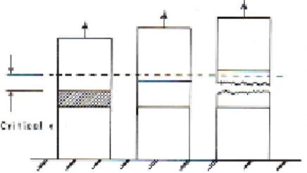
Figure 10 Simulated transverse stress and deformation distribution after cooling for three welding speeds. Welds are performed on a Fish Bone specimen that is a narrow trapezoidal plate [101].
Figure 11 Simulated effect of heat input and welding speed on solidification crack length in Fish Bone specimens of trapezoidal shape when starting from: (a) narrow edge and (b) wide edge [101].
The deformation of the fusion weld mushy zone, as a critical factor in solidification cracking, has been simulated by combining a 3D multi-scale model of solidification and microstructure with a deformation model that includes the effects of solidification shrinkage, thermo-mechanical forces and restraining forces [88]. This simulation focuses on AA6061 GTA welds. Welding speed influences the deformation rate of the weld mushy zone. Adapting Coniglio and Cross strain partition model [36,67] to a simulated solidifying mushy zone enables one to link micro-scale phenomena to macro-scale characteristics. Increasing welding speed at constant heat Q leads to higher cooling rates (Figure 12a) and higher deformation rates averaged across the weld (Figure 12b). Moreover, deformation rates are observed to decrease with increasing solid fractions. The simulated deformation rates are in agreement with experimental data performed on AA6061 GTA welds at 4 mm∙s-1 and 130 A [102]. The smaller deformation rates at higher heat inputs agree with the measured decrease in strain rate when preheating prior to welding (because of smaller temperature gradients) and the associated observation of reduced solidification cracking susceptibility [103].
14
Figure 12 Variation in AA6061 GTA welds for various welding parameters as a function of average solid fraction of (a) maximum cooling rate and (b) average internal deformation rate [88]. Captions indicate
welding speed and current, e.g. V2I95 corresponds to a speed of 2 mm.s-1 and a current of 95A.
3D Multiphysics modeling has been recently applied to Al-Mg-Si welds [83]. The model consists of four modules to cover the overall metallurgical, thermal, and mechanical aspects of fusion welding [83]. A welding solidification module creates from granular models of semi-solids the weld microstructure based upon welding conditions (Rosenthal equation) and solidification mode (Scheil-type):
2𝜋(𝑇−𝑇0)𝐾𝑅
𝑄 = 𝑒𝑥𝑝 [
−𝑠(𝑅−𝑥)
2𝛼 ] (Eq. 9)
, where R is the radial distance from the weld centre, x is the distance from the weld centre along the weld line, T0 is the initial temperature of the workpiece, s is the travel speed of the torch, Q
is the heat transferred from the torch to the metal, and K and are the thermal conductivity and diffusivity of the base metal, respectively.
A thermo-mechanical analysis module predicts the deformation of the weld mushy zone due to solidification contraction and base metal response. The deformation of each liquid channel (𝛿) is decomposed into an internal component (𝛿𝑖𝑛𝑡) and an external component (𝛿𝑒𝑥𝑡) [83]:
𝛿 = 𝛿𝑖𝑛𝑡+ 𝛿𝑒𝑥𝑡 (Eq. 10)
(𝛿𝑖𝑛𝑡) is the result of solidification shrinkage and (𝛿𝑒𝑥𝑡) is induced by the thermal expansion and contraction of surrounding base metal.
A fluid flow module calculates the variation in fluid velocity and pressure within the micro liquid channels of the semisolid. Externally-applied deformations on liquid channels act as a driving force to induce fluid flow from weld pool into the mushy zone network. The flow is calculated using Navier-Stoke and Poiseuille equations.
Once the metallurgical and thermo-mechanical conditions are calculated, a crack initiation module applies a cracking criterion (in this case Kou’s cracking criterion [10]) to identify cracked liquid channels [83]. The model was implemented for solidification cracking during autogenous GTA welding of the AA6061 aluminum alloy [83]. Welding speed and current varied from 2 to 5 mm∙s—1 and from 95 to 140 A, respectively [83]. The pressure dropped continuously up to 0.8 solid fraction and then stabilized as external deformation rates are smaller above 0.8 solid fraction (Figure 13). The pressure drop was the highest for small welding speed because of a long columnar zone present in the weld microstructure.
15
Figure 13 Variation in AA6061 GTA welds of average pressure as a function of solid fraction for a clamped weld with various welding parameters [83]. Captions indicate welding speed and current, e.g. V2I95
corresponds to a speed of 2 mm.s-1 and a current of 95A.
Combining the pressure drop with the Kou crack index defined a cracking susceptibility of the weld (Figure 14) [83]. The external lateral applied strain rate is 0.1 s—1. The crack initiation is likely to occur at the root of the liquid channels [83]. The model agrees with experimental work whereby increased travel speed lowers the susceptibility of the weld mushy zone to solidification cracking. Specifically, a faster travel speed increases the cooling rate, which lowers the number of unbridged channels capable of developing defects at high solid fractions where the accumulated deformation and slow fluid velocity can promote solidification crack initiation [83]. Calculated critical deformation rates for cracking are between 0.1 and 0.25 s-1. Moreover the model successfully predicted solidification crack localization along grain boundaries, initiation by micro-cracks formation near the fusion zone, and its growth into a macroscopic solidification crack towards the centerline [83]. All these calculations agree with experimental works of other researchers [36,76,104,105].
Figure 14 Variation in AA6061 GTA welds of Kou crack index as a function of solid fraction for a clamped weld with various welding parameters. External lateral applied strain rate is 0.1 s—1 [83]. Captions
indicate welding speed and current, e.g. V2I95 corresponds to a speed of 2 mm.s-1 and a current of
16
F. SUMMARY
During the last 20 years, interdendritic boundary conditions were examined to model solidification crack formation in welding. More recently, the grain boundary is the region of interest to better understand cracking phenomenon and in particular its relationship with welding speed. Modeling welding speed effect on solidification cracking requires: 1) microstructural simulation of solidification in the mushy zone; 2) calculations of local strain rates for crack formation in order to maintain the crack tip in the mushy zone (equals crack growth velocity); 3) add thermal fields surrounding the weld metal to calculate local tensile conditions surrounding the mushy zone and compare to critical strain rates for cracking.
Recent developments have suggested that, because of its effect on both cross-sectional area and elongation of welds, welding speed affects weldability in a different manner depending if Q, 𝑄
𝑠 or cross-sectional area remains constant. Moreover, considering local indexes such as local strain rate, or global indexes such as crack length, represent different measurements of weldability that do or do not account for thermo-mechanical field variation with welding speed, respectively. Therefore both experimental conditions and metrics must be chosen carefully to assess usefully weldability.
Numerous conclusions are drawn from this review. There are no easy rules to follow regarding travel speed and weldability because both current and welding speed must be examined simultaneously. The effect of travel speed on dendrite pressure drop and solute back-diffusion come into play when applying new cracking models but an investigation of weld speed must implement moreover modeling of the thermo-mechanical stress state in the mushy zone. Therefore, since solidification cracking is a kinetics problem, variable speed should be a useful tool to test the model. Nevertheless, selecting a proper weldability testing device is difficult as it needs to enable the investigation of both laser and arc welding, where laser welds are up to 102 times faster than arc welds. The establishment of standards for weldability testing is desired for both industrial and academic research laboratories to allow data to be reliably compared between different research laboratories [106]. The present review proves that this problem is even more important for comparing weldability data about welding speed effects on solidification cracking.
G. REFERENCES
[1] T.C. Nguyen, D.C. Weckman, D.A. Johnson, H.W. Kerr, High speed fusion weld bead defects, Sci. Technol. Weld. Join. 11 (2006) 618–633. https://doi.org/10.1179/174329306X128464. [2] T.C. Nguyen, D.C. Weckman, D.A. Johnson, H.W. Kerr, The humping phenomenon during
17 high speed gas metal arc welding, Sci. Technol. Weld. Join. 10 (2005) 447–459. https://doi.org/10.1179/174329305X44134.
[3] J. Campbell, Castings, Elsiever, 2003.
[4] N. Coniglio, C.E. Cross, Initiation and growth mechanisms for weld solidification cracking, Int. Mater. Rev. 58 (2013) 375–397. https://doi.org/10.1179/1743280413Y.0000000020. [5] J.C. Borland, Fundamentals of Solidification Cracking in Welds - Part 1, Weld. Met. Fabr.
(1979) 19–29.
[6] C.E. Cross, On the origin of weld solidification cracking, in: Hot Crack. Phenom. Welds, 2005: pp. 3–18.
[7] C.E. Cross, N. Coniglio, Weld solidification cracking: critical conditions for crack initiation and growth, in: Hot Crack. Phenom. Welds II, 2008: pp. 39–58.
[8] D.G. Eskin, L. Katgerman, A quest for a new hot tearing criterion, Metall. Mater. Trans. A Phys. Metall. Mater. Sci. 38 A (2007) 1511–1519. https://doi.org/10.1007/s11661-007-9169-7.
[9] C.D. Lundin, C.P.D. Chou, Hot Cracking Susceptibility of Austenitic Stainless Steel Weld
Metals, Weld. Res. Counc. 289 (1983) 1–79.
http://www.aws.org/wj/supplement/WJ_1982_03_s82.pdf.
[10] S. Kou, A Criterion for Cracking During Solidification, Acta Mater. 88 (2015) 366–374. https://doi.org/10.1016/j.actamat.2015.01.034.
[11] J.C. Borland, Fundamentals of Solidification Cracking in Welds - Part 2, Weld Met Fabr. 47 (1979) 99–107.
[12] W.G. Hull, D. Adams, Part II - Review of published information on weld cracking in aluminium alloys with particular reference to Al-Mg-Si alloys, Br. Weld. J. (1954) 464–467. [13] V.N. Saveiko, Theory of Hot Cracking, Russ. Cast. Prod. (1961) 453–456.
[14] C.H. Dickhaus, L. Ohm, S. Engler, Mechanical properties of solidifying shells of aluminium alloys, AFS Trans. 101 (1994) 677–684.
[15] D.J. Lahaie, M. Bouchard, Physical Modeling of the Deformation Mechanisms of Semisolid Bodies and a Mechanical Criterion for Hot Tearing, Met. Mat. Trans. Bt. Trans. 32B (2001) 697–705.
[16] J.A. Brooks, J.J. Dike, Modeling Weld Solidification Cracking Behavior in Aluminum Alloys-Analysis of Fracture lnitiation, in: Trends Weld. Res. Proc. 5th Int. Conf. Mater. Park. Ohio, USA, 2005: pp. 695–700.
18 [18] N.N. Prokhorov, M.N. Gavrilyuk, Strain behaviour during solidification after welding, Svar.
Proiz. 6 (1971) 5–9.
[19] T. Senda, T., Matsuda, F., Takano, G., Watanabe, K., Kobayashi, T., Matsuzaka, Fundamental investigations on solidification crack susceptibility for weld metals with trans-varestraint test, Trans. JWS. 2 (1971) 1–22. https://doi.org/10.2207/qjjws1943.41.709.
[20] W.I. Pumphrey, J.V. Lyons, Cracking during the casting and welding of the more common binary aluminum alloys, JIM. 74 (1948) 439–455.
[21] J.C. Borland, Suggested explanation of hot cracking in mild and low alloy steel welds, Br. Weld. J. (1961) 526–540.
[22] K. Nakata, F. Matsuda, Evaluations of ductility characteristics and cracking susceptibility of Al alloys during welding, Trans. JWRI. 24 (1995) 83–94.
[23] W.I. Pumphrey, D.C. Moore, Cracking during and after solidification in some aluminium-copper-magnesium alloys of high purity, 1JIM. 73 (1947) 425–438.
[24] H.F. Bishop, C.G. Ackerlind, W.S. Pellini, Metallurgy and mechanics of hot tearing, TAFS. 60 (1952) 818–833.
[25] C. Bernhard, R. Pierer, C.M. Chimani, A new hot tearing criterion for the continuous casting of steel, SP’07, 5th Decenn. Conf. Solidif. Process. Sheffield, UK, 23-25 July 2007. (2007) 525–530.
[26] W.R. Apblett, W.S. Pellini, Factors which influence weld hot cracking, Weld. J. (1954) 83s-90s.
[27] M. M’Hamdi, A. Mo, H.G. Fjær, TearSim: A two-phase model addressing hot tearing formation during aluminum direct chill casting, Metall. Mater. Trans. A. 37 (2006) 3069– 3083. https://doi.org/10.1007/s11661-006-0188-6.
[28] A. Mo, I. Farup, Hot tearing and thermally induced deformation in the mushy zone, in: Model. Cast. Welding, Adv. Solidif. Process. IX, 2000: pp. 56–62.
[29] M’Hamdi M., Ellingsen K., Mortensen D., A three-phase approach for th emodelling of hot tearing formation in DC casting of aluminium ingots, in: Proc. 5th Decenn. Int. Conf. Solidif. Process., Sheffield, 2007: pp. 536–539.
[30] M. Mhamdi, A. Mo, C.L. Martin, Two-phase modelling directed towards hot tearing formation in aluminium direct chill casting, Met. Trans. A. 33A (2002) 2081–2093.
[31] I.I. Novikov, O.E. Grushko, Hot cracking susceptibility of Al–Cu–Li and Al–Cu–Li–Mn alloys, Mater. Sci. Technol. 11 (1995) 926–932. https://doi.org/10.1179/mst.1995.11.9.926. [32] H. Nagaumi, T. Umeda, Prediction of internal cracking in a direct-chill cast, high strength,
https://doi.org/10.1016/S1471-19 5317(02)00042-1.
[33] M.R. Ridolfi, S. Fraschetti, A. De Vito, L.A. Ferro, Mathematical modeling of hot tearing in the solidification of continuously cast round billets, Metall. Mater. Trans. B Process Metall. Mater. Process. Sci. 41 (2010) 1293–1309. https://doi.org/10.1007/s11663-010-9427-8. [34] M.O. El-Bealy, Interdendritic strain and macrosegregation-coupled phenomena for
interdendritic crack formationin direct-chill cast sheet ingots, Metall. Mater. Trans. B Process Metall. Mater. Process. Sci. 43 (2012) 635–656. https://doi.org/10.1007/s11663-011-9616-0.
[35] Suyitno, W.H. Kool, L. Ketgerman, Evaluation of mechanical and non-mechanical hot tearing criteria for DC casting of an aluminum alloy, in: Light Met. 2003, 2003: pp. 753–758. [36] N. Coniglio, C.E. Cross, Mechanisms for solidification crack initiation and growth in aluminum welding, Metall. Mater. Trans. A. 40 (2009) 2718–2728. https://doi.org/10.1007/s11661-009-9964-4.
[37] M. Rappaz, J. Drezet, M. Gremaud, A New Hot-Tearing Criterion, 30 (1999) 449–455. [38] T.W. Clyne, G.J. Davies, Comparison between experimental data and theoretical
predictions relating to dependence of solidification cracking on composition, Solidif. Cast.
Met. Proc. an Int. Conf. Solidif. (1979) 275–278.
https://ndlopac.ndl.go.jp/F/KR79PSQ7E4N6B2QTNC1PUUX3YKJ62SQARV52BE1X1H4G3H DCR2-31212?func=full-set-set&set_number=670580&set_entry=000012&format=999. [39] L. Katgerman, A Mathematical Model for Hot Cracking of Aluminum Alloys During D.C.
Casting, JOM. 34 (1982) 46–49. https://doi.org/10.1007/BF03339110.
[40] N. Hatami, R. Babaei, M. Dadashzadeh, P. Davami, Modeling hot tearing during solidification, J. Mater. Process. Technol. 205 (2008) 506–513.
[41] V. Mathier, S. Vernède, P. Jarry, M. Rappaz, Two-phase modeling of hot tearing in aluminum alloys: Applications of a semicoupled method, Metall. Mater. Trans. A Phys. Metall. Mater. Sci. 40 (2009) 943–957. https://doi.org/10.1007/s11661-008-9772-2. [42] M. Bellet, O. Cerri, M. Bobadilla, Y. Chastel, Modeling hot tearing during solidification of
steels: Assessment and improvement of macroscopic criteria through the analysis of two experimental tests, Metall. Mater. Trans. A Phys. Metall. Mater. Sci. 40 (2009) 2705–2717. https://doi.org/10.1007/s11661-009-9955-5.
[43] S. Mihanyar, A. Mo, M. M’Hamdi, K. Ellingsen, Modeling of de-cohesion and the initiation of hot tearing in coherent mushy zones of metallic alloys, Metall. Mater. Trans. A Phys. Metall. Mater. Sci. 42 (2011) 1887–1895. https://doi.org/10.1007/s11661-010-0581-z. [44] J. Drezet, M. Gremaud, R. Graf, M. Gäumann, A New Hot Tearing Criterion for Steel, in: 4th
20 [45] J.-M. Drezet, D. Allehaux, Application of the Rappaz-Drezet-Gremaud Hot Tearing Criterion to Welding of Aluminium Alloys, in: Springer (Ed.), Hot Crack. Phenom. Welds II, 2008: pp. 27–45. https://doi.org/10.1007/978-3-540-78628-3_2.
[46] J.-M. Drezet, M. Rappaz, Prediction of Hot Tears in DC-Cast Aluminum Billets, in: J.L. Anjier (Ed.), Light Met. 2001, TMS, 2001: pp. 887–893.
[47] M. Easton, L. Sweet, H. Wang, J. Grandfield, C.J. Davidson, D.H. Stjohn, M.J. Couper, Observation and prediction of the hot tear susceptibility of ternary Al-Si-Mg alloys, Metall. Mater. Trans. A Phys. Metall. Mater. Sci. 43 (2012) 3227–3238. https://doi.org/10.1007/s11661-012-1132-6.
[48] C. Hagenlocher, D. Weller, R. Weber, T. Graf, Analytical Description of the Influence of the Welding Parameters on the Hot Cracking Susceptibility of Laser Beam Welds in Aluminum Alloys, Metall. Mater. Trans. A. 50 (2019) 5174–5180. https://doi.org/10.1007/s11661-019-05430-7.
[49] C. Monroe, C. Beckermann, Development of a hot tear indicator for steel castings, Mater. Sci. Eng. A. 413–414 (2005) 30–36. https://doi.org/10.1016/j.msea.2005.09.047.
[50] M. M’Hamdi, A. Mo, On modelling the interplay between microporosity formation and hot tearing in aluminum direct-chill casting, Mat. Sci. Eng. A. 413–414 (2005) 105–108.
[51] J.F. Grandfield, C.J. Davidson, J.A. Taylor, Applciation of a new hot tearing analysis to horizontal direct chill cast magnesium alloy AZ91, in: TMS (Ed.), Light Met. 2001, 2001: pp. 895–901.
[52] W. Rindler, K. Kozeschnik, N. Enzinger, B. Buchmayr, A modified hot tearing criterion for steels, in: Math. Model. Weld Phenom. 6, Maney, 2002: pp. 819–835.
[53] U. Feurer, Influence of alloy composition and solidification conditions on dendrite arm spacing, feeding, and hot tearing properties of aluminum alloys, in: Proc. Int. Symp. Eng. Alloy., Delft, 1977: pp. 131–145.
[54] J. Liu, S. Kou, Effect of diffusion on susceptibility to cracking during solidification, Acta Mater. 100 (2015) 359–368. https://doi.org/10.1016/j.actamat.2015.08.064.
[55] T. Soysal, S. Kou, A simple test for assessing solidification cracking susceptibility and checking validity of susceptibility prediction, Acta Mater. 143 (2018) 181–197. https://doi.org/10.1016/j.actamat.2017.09.065.
[56] S. Geng, P. Jiang, X. Shao, G. Mi, H. Wu, Y. Ai, Effects of back-diffusion on solidi fi cation cracking susceptibility of Al-Mg alloys during welding : A phase-field study, Acta Mater. 160 (2018) 85–96. https://doi.org/10.1016/j.actamat.2018.08.057.
[57] K. Liu, S. Kou, Susceptibility of magnesium alloys to solidification cracking, Sci. Technol. Weld. Join. 0 (2019) 1–7. https://doi.org/10.1080/13621718.2019.1681160.
21 [58] C.E. Cross, D.L. Olson, Hot tearing model to assess aluminum weldability, in: Alum. Alloy. -
Their Phys. Mech. Prop. Vol. III, Charlottesville, Virginia, USA, 1986: pp. 1869–1875. [59] M. Rappaz, A. Jacot, W.J. Boettinger, Last-stage solidification of alloys: theoretical model
of dendrite-arm and grain coalescence, Met. Mat. Trans. Alurgical. 34A (2003) 467–479. [60] F. Bodaghi, M. Movahedi, A.H. Kokabi, R. Tavakoli, Effect of solid fraction, grain
misorientation and grain boundary energy on solidification cracking in weld of Al-Cu aluminum alloys, Mater. Res. Express. 6 (2019). https://doi.org/10.1088/2053-1591/ab20ee.
[61] C. Davidson, D. Viano, L. Lu, D. Stjohn, Observation of crack initiaiton during hot tearing, Int. J. Cast Met. Res. 19 (2006) 59–65.
[62] J. Campbell, M. Tiryakiog, Bifilm Defects in Ni-Based Alloy Castings, Met. Mat. Trans. B. 43B (2012) 902–914. https://doi.org/10.1007/s11663-012-9655-1.
[63] D. Fabrègue, A. Deschamps, M. Suéry, H. Proudhon, Hot Tearing During Laser Butt Welding of 6xxx Aluminium Alloys : Process Optimisation and 2D / 3D Characterisation of Hot Tears, in: Hot Crack. Phenom. Welds II, 2007: pp. 241–253.
[64] S.A. David, C.L. White, Formation of Hot Cracks in Austenitic Stainless Steel Welds — Solidification Cracking, Weld. Res. Suppl. 209-s (1986) 203–212.
[65] M. Shibahara, H. Serizawa, H. Murakawa, Finite element method for hot cracking analysis using temperature dependent interface element, in: Hot Crack. Phenom. Welds, Springer, 2005: pp. 253–257.
[66] D.G. Eskin, Suyitno, L. Katgerman, Mechanical properties in the semi-solid state and hot tearing of aluminium alloys, Prog. Mater. Sci. 49 (2004) 629–711. https://doi.org/10.1016/S0079-6425(03)00037-9.
[67] M. Braccini, C.L. Martin, M. Suery, Y. Brechet, Hot tearing phenomena in Al-Cu alloys: grain refinement effect, Matériaux Tech. 5–6 (2000) 19–24.
[68] M. Braccini, C. Martin, M. Suery, Relation Between mushy zone rheology and hot tearing phenomena in Al-Cu alloys, Model. Cast. Weld. Adv. Solidif. Process. IX. (2000) 18–24. papers3://publication/uuid/B3582EAE-4EBC-48C2-8D43-F45001DFB1A4.
[69] S. Bhagavath, B. Cai, R. Atwood, M. Li, B. Ghaffari, P.D. Lee, S. Karagadde, Combined Deformation and Solidification-Driven Porosity Formation in Aluminum Alloys, Metall. Mater. Trans. A Phys. Metall. Mater. Sci. 50 (2019) 4891–4899. https://doi.org/10.1007/s11661-019-05378-8.
[70] S.D. Felicelli, L. Wang, C.M. Pita, E.E. De Obaldia, A model for gas microporosity in aluminum and magnesium alloys, Metall. Mater. Trans. B Process Metall. Mater. Process. Sci. 40 (2009) 169–181. https://doi.org/10.1007/s11663-008-9217-8.
22 [71] J. Draxler, J. Edberg, J. Andersson, L.E. Lindgren, Modeling and simulation of weld solidification cracking part I, Weld. World. 63 (2019) 1883–1901. https://doi.org/10.1007/s40194-019-00784-3.
[72] J. Draxler, J. Edberg, J. Andersson, L.-E. Lindgren, Modeling and simulation of weld solidification cracking part II, Weld. World. 63 (2019) 1503–1519. https://doi.org/10.1007/s40194-019-00761-w.
[73] J. Draxler, J. Edberg, J. Andersson, L. -E. Lindgren, Modeling and simulation of weld solidification cracking part III, Weld. World. 63 (2019) 1883–1901. https://doi.org/10.1007/s40194-019-00784-3.
[74] G. Argawa, H. Gao, M. Armithalingam, M. Hermans, Study of Solidification Cracking Susceptibility during Laser Welding in an Advanced High Strength Automotive Steel, Metals (Basel). 8 (2018) 1–15. https://doi.org/10.3390/met8090673.
[75] J.A. Brooks, A.W. Thompson, Microstructural development and solidification cracking susceptibility of austenitic stainless steel welds, Int. Mater. Rev. 36 (1991) 16–44.
[76] N. Coniglio, C.E. Cross, T. Michael, M. Lammers, Defining a critical weld dilution to avoid solidification cracking in aluminum, Weld. J. (Miami, Fla). 87 (2008).
[77] C.E. Cross, N. Coniglio, P. Schempp, M. Mousavi, Critical Conditions for Weld Solidification Crack Growth, in: Hot Crack. Phenom. Welds III, Springer, 2011: pp. 25–41. https://doi.org/10.1007/978-3-642-16864-2.
[78] M.G. Chu, D.A. Granger, The Tensile Behaviour and Cracking Tendency of Partially Solidified Aluminum Alloys, Proc. 4th Decenn. Int. Conf. Solidif. Process. (1997) 198–202. papers3://publication/uuid/A42D67E4-CB92-4849-93A3-7C17EB131393.
[79] Y. Lu, M. Li, X. Li, Deformation behavior and constitutive equation coupled the grain size of semi-solid aluminum alloy, J. Mater. Eng. Perform. 19 (2010) 1337–1343. https://doi.org/10.1007/s11665-010-9627-z.
[80] T.G. Nguyen, D. Favier, M. Suery, Theoretical and experimental study of the isothermal mechanical behaviour of alloys in the semi-solid state, Int. J. Plast. 10 (1994) 663–693. [81] P. Grasso, COALESCENCE AND MECHANICAL BEHAVIOUR OF SEMI-SOLID ALUMINIUM
ALLOYS IN RELATION TO HOT TEARING, 2004.
[82] M. M’hamdi, A. Mo, C.L. Martin, Two-phase modeling directed toward hot tearing formation in aluminum direct chill casting, Metall. Mater. Trans. A Phys. Metall. Mater. Sci. 33 (2002) 2081–2093. https://doi.org/10.1007/s11661-002-0040-6.
[83] H.R.Z. Rajani, A.B. Phillion, 3D multi-scale multi-physics modelling of hot cracking in welding, Mater. Des. 144 (2018) 45–54. https://doi.org/10.1016/j.matdes.2018.02.007. [84] K. Ichikawa, H.K.D.H. Bhadeshia, D.C.J. MacKay, Model for solidification cracking in low
23 alloy steel weld metals, Sci. Technolology Weld. Join. 1 (1996) 43–50.
[85] J.J. Dike, J.A. Brooks, M. Li, Comparison of failure criteria in weld solidification cracking simulations, in: Math. Model. Weld Phenom. 4, Inst Materials, London, 1998: pp. 199–222. [86] Z. Feng, A. David, T. Zacharia, C.L. Tsai, Quantification of thermomechanical conditions for weld solidification cracking, Sci. Technol. Weld. Join. 2 (1997) 11–19. https://doi.org/10.1179/stw.1997.2.1.11.
[87] A. Niel, C. Bordreuil, F. Deschaux-Beaume, G. Fras, Modetling hot cracking in 6061 aluminium atloy weld metat with microstructure based criterion, Sci. Technol. Weld. Join. 18 (2013) 154–160.
[88] H.R.Z. Rajani, A.B. Phillion, 3-D multi-scale modeling of deformation within the weld mushy zone, Mater. Des. 94 (2016) 536–545. https://doi.org/10.1016/j.matdes.2016.01.071. [89] H. Murakawa, H. Serizawa, M. Shibahara, Prediction of welding hot cracking using
temperature dependent interface element, in: Math. Model. Weld Phenom. 7, 2005: pp. 539–554.
[90] M. Shibahara, S. Itoh, H. Serizawa, H. Murakawa, Numerical prediction of welding hot cracking using three-dimensional FEM with temperature dependent interface element, Weld. World. 49 (2005) 50–57.
[91] Z. Feng, A computational analysis of thermal and mechanical conditions for weld metal solidification cracking, Weld. World. 33 (1994) 340–347.
[92] Z. Feng, T. Zacharia, S. David, On the thermomechanical conditions for weld metal solidification cracking, in: Math. Model. Weld Phenom. 3, The Institute of Materials, 1996: pp. 114–148.
[93] H. Herold, M. Streitenberger, Consideration of the Welding Process as a thermo-physical Mechanism to Control Cracking in Weldments, in: Hot Crack. Phenom. Welds II, Springer, 2008: pp. 67–75.
[94] J.J. Dike, J.A. Brooks, J.S. Krafcik, Finite Element Modeling and Verification of Thermal-Mechanical Behavior in the Weld Pool Region, in: Trends Weld. Res. Proc. 4th Int. Conf., 1995: pp. 159–164. https://doi.org/10.1007/978-1-4471-4330-7_3.
[95] O. Hunziker, D. Dye, S.M. Roberts, R.C. Reed, A coupled approach for the prediciton of solidification cracking during the welding of superalloys, in: Hot Crack. Phenom. Welds, Springer, 2005: pp. 299–319.
[96] Y.H. Wei, Z.B. Dong, R.P. Liu, Z.J. Dong, Three-dimensional numerical simulation of weld solidification cracking, Model. Simul. Mater. Sci. Eng. 13 (2005) 437–454. https://doi.org/10.1088/0965-0393/13/3/012.
24 approach to modeling of solidification cracking in welds, in: Hot Crack. Phenom. Welds, Springer, Berlin, Heidelberg, 2005: pp. 223–244.
[98] J.A. Brooks, J.J. Dike, J.S. Krafcik, On modeling weld solidification cracking, in: Proc. Intern. Conf. Model. Control Join. Process., 1993: pp. 174–185.
[99] S. Chen, G. Guillemot, C.A. Gandin, Three-dimensional cellular automaton-finite element modeling of solidification grain structures for arc-welding processes, Acta Mater. 115 (2016) 448–467. https://doi.org/10.1016/j.actamat.2016.05.011.
[100] J.-M. Drezet, V. Mathier, D. Allehaux, Finite element modelling of laser beam welding of aluminium alloys with special attention to hot cracking in transient regimes, in: Math. Model. Weld Phenom. 8, 2006: pp. 137–152.
[101] M. Shibahara, H. Serizawa, H. Murakawa, Finite element method for hot cracking analysis using temperature dependent interface element (Report II), Trans. JWRI. 29 (2000) 59–64. [102] N. Coniglio, C.E. Cross, T. Michael, M. Lammers, Defining a critical weld dilution to avoid
solidification cracking in aluminum, Weld. J. 87 (2008) 237s-247s.
[103] M. Sheikhi, F. Malek Ghaini, H. Assadi, Solidification crack initiation and propagation in pulsed laser welding of wrought heat treatable aluminium alloy, Sci. Technol. Weld. Join. 19 (2014) 250–255. https://doi.org/10.1179/1362171813y.0000000190.
[104] N. Coniglio, C.E. Cross, Weld parameter and minor element effects on solidification crack initiation in aluminium, in: Hot Crack. Phenom. Welds II, Springer, 2008: pp. 277–310. [105] R.A. Chihoski, The Character of Stress Fields Around a Weld Arc Moving on Aluminum
Sheet, Weld. J. 168 (1972) 9s-18s.
[106] N. Coniglio, C.E. Cross, Towards Establishment of Weldability Testing Standards for Solidification Cracking, in: Hot Crack. Phenom. Welds IV, 2016: pp. 37–66.

![Figure 4 EBSD map of aluminum AA6052 laser welds revealing intergrain growth of solidification crack [63]](https://thumb-eu.123doks.com/thumbv2/123doknet/7431489.219847/8.918.362.559.749.944/figure-ebsd-aluminum-laser-revealing-intergrain-growth-solidification.webp)
![Figure 5 Schematics of intersecting grains occurring during stainless steel solidification [75]](https://thumb-eu.123doks.com/thumbv2/123doknet/7431489.219847/9.918.282.633.575.776/figure-schematics-intersecting-grains-occurring-stainless-steel-solidification.webp)
![Figure 6 Cracking susceptibility of Alloy 6060 for variable 4043 filler dilution shown as a function of local strain rate [76]](https://thumb-eu.123doks.com/thumbv2/123doknet/7431489.219847/10.918.334.586.109.294/figure-cracking-susceptibility-alloy-variable-filler-dilution-function.webp)
![Figure 8 Methodology for modeling of solidification cracking during welding [95].](https://thumb-eu.123doks.com/thumbv2/123doknet/7431489.219847/12.918.360.582.775.925/figure-methodology-modeling-solidification-cracking-welding.webp)
![Figure 9 weldability diagram showing range of welding speed and current generating solidification cracking in full-penetration IN718 GTA welds [95]](https://thumb-eu.123doks.com/thumbv2/123doknet/7431489.219847/13.918.341.574.282.441/figure-weldability-diagram-showing-generating-solidification-cracking-penetration.webp)

![Figure 13 Variation in AA6061 GTA welds of average pressure as a function of solid fraction for a clamped weld with various welding parameters [83]](https://thumb-eu.123doks.com/thumbv2/123doknet/7431489.219847/16.918.370.567.108.276/figure-variation-average-pressure-function-fraction-clamped-parameters.webp)
