Science Arts & Métiers (SAM)
is an open access repository that collects the work of Arts et Métiers Institute of Technology researchers and makes it freely available over the web where possible.
This is an author-deposited version published in: https://sam.ensam.eu
Handle ID: .http://hdl.handle.net/10985/20278
To cite this version :
Francesco CARERI, Stano IMBROGNO, Domenico UMBRELLO, Moataz M. ATTALLAH, José OUTEIRO, António C. BATISTA - Machining and heat treatment as post-processing strategies for Ni-superalloys structures fabricated using direct energy deposition - Journal of Manufacturing Processes - Vol. 61, p.236-244 - 2021
Machining and Heat Treatment as Post-Processing Strategies for Ni-Superalloys
Structures Fabricated using Direct Laser Deposition
Francesco Careria, b, Stano Imbrognob,*, Domenico Umbrelloa, Moataz M. Attallahb, José Outeiroc, António C. Batistad
a Department of Mechanical, Energy and Management Engineering, University of Calabria, Rende, CS 87036, Italy
b School of Metallurgy and Materials, University of Birmingham, Birmingham B15 2TT, UK
c Arts et Metiers Institute of Technology, LABOMAP, HESAM University, Rue Porte de Paris, F-71250 Cluny, France
d
University of Coimbra, CFisUC, Department of Physics, 3004-516 Coimbra, Portugal
*Corresponding author: s.imbrogno@bham.ac.uk, Tel.: +447882267415.
Abstract
The aim of this study is to determine the most suitable post-processing sequence for additive manufacturing to reach an enhanced surface integrity of components in Inconel 718 superalloy. These components are fabricated by Direct Laser Deposition (DLD) followed by two typical processing methods: machining and heat treatment. The effect of post-processing sequence (machining + heat treatment or heat treatment + machining) and the corresponding effects on the surface integrity of these components were investigated in terms of surface finishing, microstructure, micro-hardness and residual stresses. Finally, suitable solutions in terms of additive manufacturing - post-process operations have been reported.
Keywords: Machining; Additive Manufacturing; Surface integrity
Manuscript Click here to view linked References
1 2 3 4 5 6 7 8 9 10 11 12 13 14 15 16 17 18 19 20 21 22 23 24 25 26 27 28 29 30 31 32 33 34 35 36 37 38 39 40 41 42 43 44 45 46 47 48 49 50 51 52 53 54 55 56 57 58 59 60 61
1. Introduction
Additive Manufacturing (AM) offers a new technique to manufacture complicated parts. In the last decade the AM has attracted the interest from relevant industrial areas such as aerospace, automotive and medical thanks to its flexibility and potentiality to create near-net-shape components using an innovative layer-by-layer manufacturing technology. [1, 2]. Among all the AM techniques, the Direct Energy Deposition (DED) is considered the most promising in performing repairing actions on high mechanical performance components (e.g. turbine blades or blisks) as well as producing parts with very complex thin shape. This process uses a thermal source, usually, a laser or electron beam, to melt the metal powder and deposit a layer on a substrate [3]. In contrast, the parts produced by DED manifest very poor surface quality (high surface roughness) as well as the usually miss the tolerance required. Therefore, the parts usually need subtractive manufacturing post-processes in order to match the high accuracy and surface quality required in the standards. The Nickel-based superalloy Inconel718 is known as a difficult-to-cut material because of its high strength at high temperature, high reaction with tool materials and low thermal diffusivity [4]. More often, the components produced with Inconel718 require some specific heat treatments in order to customize the mechanical and microstructural properties, especially if produced by DED or other AM techniques [5]. This is a further problem for the machinability of components since after the heat treatments this alloy manifests extraordinary mechanical properties. For this reason, several works were conducted about the study of the best combination of cutting parameters to machine the Inconel718 [4-6]. Although many of them assessed the machinability of the material in wrought or cast condition, the one related to the parts produced by DED or further laser metal depositions process is still not clear. Generally, the actual manufacturing procedure applied by the industries (known also as hybrid additive manufacturing) is to deposit the material by DED process, then the component is firstly heat treated and after machined for achieving the final shape and the desired surface quality. The present work aims to study and propose newly and different industrial strategies to customize and achieve the
1 2 3 4 5 6 7 8 9 10 11 12 13 14 15 16 17 18 19 20 21 22 23 24 25 26 27 28 29 30 31 32 33 34 35 36 37 38 39 40 41 42 43 44 45 46 47 48 49 50 51 52 53 54 55 56 57 58 59 60 61
required quality depending on the application of the components. Three different hybrid additive manufacturing routines combined with the heat treatments were investigated. In particular, the machinability and the surface integrity of the as deposited and post heat treated Inconel718 were characterized. Microstructure, micro-hardness and residual stresses induced by the manufacturing processes were investigated in order to analyse as the entire process affects the final quality of the produced part.
2. Material and methods
The material used was the Nickel-based superalloy Inconel718 provided as metal powder with a particle size varying from 45 to 106 µm. The cylindrical bars (120 mm length and 33 mm of diameter) were produced with a 5 axis CNC machine equipped with a TruDisk 4002 disk laser with a wavelength of 1030 nm (Fig. 1(a)). The process parameters were the laser power of 400 W, scan speed of 275 mm/min and powder flow rate 9.8 g/min, while the scan strategy is showed in Fig. 1(b).
Fig. 1. (a) DLD set-up; (b) schematic representation of the scan strategy used to build by DLD; (c) turning
set-up, microstructural features (cross section) of the samples as deposited (AD), after heat treatment (HT).
1 2 3 4 5 6 7 8 9 10 11 12 13 14 15 16 17 18 19 20 21 22 23 24 25 26 27 28 29 30 31 32 33 34 35 36 37 38 39 40 41 42 43 44 45 46 47 48 49 50 51 52 53 54 55 56 57 58 59 60 61
The powder was spread into the melt pool by a three-beam nozzle while the argon was shielding the pool to avoid oxidation phenomena. The focus of the laser was set to get a beam spot of approximately 1 mm while the stand-off distance was set equal to 10 mm. With this configuration, the auto compensation of the material deposited was triggered and this allowed to have a good deposition rate and high geometrical accuracy [7]. Since the DLD process produces parts with low surface quality (surface roughness commonly higher than 30 µm [8]) as well as poor mechanical properties (missing the strengthening phases), post-processes treatment such as machining (to improve the surface quality) and heat treatment (to enhance the mechanical properties) were carried out. The cylindrical specimens were turned on 2 axis CNC lathe under dry cutting condition as the most representative case for the hybrid additive manufacturing. The cutting speed was based on three levels (70, 90 and 120 m/min), the feed rate was based on two levels (0.1 and 0.2 mm/rev) while the depth of cut was kept constant (0.5 mm). The mentioned cutting parameters are usually recommended for machining Nickel-based superalloys as suggested by the tool maker when a tool holder DDJNR 2525M 15 and tool DNMG 15 06 12-SMR S05F are used. The heat treatments selected for the Inconel718 were suggested by the SAE AMS 5583D [9]. The heat treatment consists of three steps: (i) the homogenization treatment to transform the dendritic in an equiaxed microstructure (1093±14°C for 2h and air cooling); (ii) solution treatment to dissolve (mostly) the Laves phase (968±14°C for 1h and air cooling); (iii) double aging treatment, to form the γ' and the γ'' phases, responsible of the strengthening of the material (718±8°C for 8 h, cool it down to 621±8°C and hold for 8h, air cooling to room temperature). In order to understand the effect of the different post-processes on the overall final quality of the produced parts, a combination of heat-treatment and machining steps and vice versa was investigated. In detail, the case studies are identified as: as deposited (AD), heat treated (HT) that considered the material after the 3-steps heat treatment, double aged (DA) that consider the material after only double aging step. The machining (M) operation is also identified as another manufacturing step. Therefore, the three manufacturing routes studied are: AD+M, AD+HT+M, AD+M+DA. The case AD+M+HT was not considered since the HT induced oxidation phenomena.
1 2 3 4 5 6 7 8 9 10 11 12 13 14 15 16 17 18 19 20 21 22 23 24 25 26 27 28 29 30 31 32 33 34 35 36 37 38 39 40 41 42 43 44 45 46 47 48 49 50 51 52 53 54 55 56 57 58 59 60 61
The machinability was assessed in terms of the cutting forces (cutting and thrust components) while the thermal gradient (frontal surface of the chip) was evaluated by an infrared (IR) camera. Preliminary calibration of the IR camera emissivity (0.5) was carried out by matching the temperature registered via thermocouple on a small sample heated on a hot surface.
Fig. 2. Schematization of cross section of the sample for (a) microstructural and (b) residual stress analysis.
The surface quality after the post-processes has been evaluated in terms of surface roughness (Sa) by
a non-contact 3D confocal profilometer. The micro-hardness (HV0.025) on surface and beneath the machined part was measured on the polished cross section of the samples. Subsequently, the samples were etched through electrolytic etching (H3PO4 voltage of 6V and 20s) to reveal the microstructure. The microstructural features and the alterations were assessed by means of the Scanning Electron Microscopy (SEM) and Electron Backscatter Diffraction (EBSD), as represented in Fig. 2(a). Finally, the residual stresses (RS) were analysed in the surface and subsurface of the samples by X-ray diffraction technique [10]. X-ray Mn-Kα radiation was used to determine the elastic strains in the
{311} diffraction planes (2θ≈152°) of the crystallographic structure of the Inconel718 alloy, using 22° ψ angles in the range ±44°. Residual stresses were determined in the direction of the primary motion (hoop) and in the direction of the feed motion (axial), as reported in Fig. 2(b).
1 2 3 4 5 6 7 8 9 10 11 12 13 14 15 16 17 18 19 20 21 22 23 24 25 26 27 28 29 30 31 32 33 34 35 36 37 38 39 40 41 42 43 44 45 46 47 48 49 50 51 52 53 54 55 56 57 58 59 60 61
3. Results and Discussion
3.1 Forces and temperatures in machining
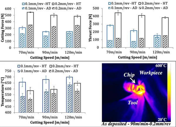
Fig. 3 reports the measured cutting and thrust forces as well as the chip temperature during the cutting process. As expected, the machinability of the AD+HT+M material was lower than the AD+M since the precipitation strengthening phases made the material harder. In general, both the cutting and thrust forces decreased when the cutting speed increased while higher feed rate led to higher forces when the AD+HT+M material was machined. In contrast, the AD+M showed lower cutting force when the cutting speed of 70 and 90 m/min (f=0.1mm/rev) are used while with 120m/min the wear started to affect the tool tip resulting in higher force. More significant differences are denoted when the feed was set to 0.2mm/rev. In this case, the AD+M parts showed a better machinability compared to AD+HT+M (the cutting forces lower than 40%-50% while the thrust force lower than 80%). In addition, the maximum chip temperature is lower when machining the AD+M samples compared to machining AD+HT. As consequence, the tool life expected by machining of AD+M samples is expected to be higher than that of machining AD+HT+M.
1 2 3 4 5 6 7 8 9 10 11 12 13 14 15 16 17 18 19 20 21 22 23 24 25 26 27 28 29 30 31 32 33 34 35 36 37 38 39 40 41 42 43 44 45 46 47 48 49 50 51 52 53 54 55 56 57 58 59 60 61
Fig. 3. Main variables of machining process. (a) cutting force; (b) thrust force; (c) maximum temperature.
3.2 Surface Roughness
The surface roughness in terms of Sa is showed in Fig. 4. The average value of the as deposited
samples depends on the DLD process parameters; it decreases with increasing of laser power and increases with increasing of scan speed.
1 2 3 4 5 6 7 8 9 10 11 12 13 14 15 16 17 18 19 20 21 22 23 24 25 26 27 28 29 30 31 32 33 34 35 36 37 38 39 40 41 42 43 44 45 46 47 48 49 50 51 52 53 54 55 56 57 58 59 60 61
Fig. 4. Sa with different post-process parameters and heat treatments.
The average Sa of 56 µm was measured on the bars after the AD due to the DLD process parameters
set. The combination of the feed rate (higher value) and the heat treatment played an important role on the surface quality. While the lower feed rate allowed to achieve low value of Sa, on the contrary,
the HT and the higher feed rate led to a critical change on the surface quality. This effect is also amplified when higher cutting speed are used during the AD+HT+M. Similar observation with different value of feed rate are highlighted in [11]. Although the surface roughness is much lower than the initial state (56 m), the Sa of the AD+M is better than the AD+HT+M. The AD material
(not heat treated) showed better ductility (as also confirmed by the cutting forces) and this allowed to reduce the wear phenomena of the tool leading to a better surface quality. Moreover, under dry machining the surface roughness has the tendency to decrease with increasing of cutting speed [12]. However, when the AD+HT+M, higher speeds seriously triggered wear phenomena compromising the Sa value. 3.3 Microstructure 1 2 3 4 5 6 7 8 9 10 11 12 13 14 15 16 17 18 19 20 21 22 23 24 25 26 27 28 29 30 31 32 33 34 35 36 37 38 39 40 41 42 43 44 45 46 47 48 49 50 51 52 53 54 55 56 57 58 59 60 61
Fig. 5 shows the microstructure of the cross section near the machined surface when the most critical cutting parameters were used. It is clearly visible the impact of the combination between machining and heat treatment on the microstructural state of the material. Indeed, the deformation behaviour as well as the affected layer (AL) are different (Fig. 5(a), (b) and (c)).
Fig. 5. Cross section of the machined bars (120m/min - 0.2mm/rev). (a) AD+M+DA; (b) AD+HT+M; (c)
AD+M; (d), (e) and (f) EBSD and KAM map of the affected layer.
The AD+HT+M samples always showed the slip bands formation while smeared material (suggesting more ductility) due to the tool action was observed in AD+M samples. Moreover, the Laves phases are somewhere trapped into the deformed material (Fig. 5(c)). Consequently, it is clear that the material behaviour during the machining process is changing between ductile and strain hardened. Although, the micrographs of the other samples are missing, the thickness of AL increased when the cutting speed and feed rate increased and the grains (dendritic in AD+M, AD+M+DA and equiaxed in AD+HT+M) are mainly deformed following the cutting direction. Due to the heat treatments, the AL of the AD+HT+M was deeper than the AD+M as also showed by the hardness measurements
1 2 3 4 5 6 7 8 9 10 11 12 13 14 15 16 17 18 19 20 21 22 23 24 25 26 27 28 29 30 31 32 33 34 35 36 37 38 39 40 41 42 43 44 45 46 47 48 49 50 51 52 53 54 55 56 57 58 59 60 61
(Fig. 6), while no dissimilarities were expected between AD+M and AD+M+DA. The intense plastic deformation induced by 90 and 120m/min (f=0.2mm/rev), led to the formation of a thin plastically deformed band and similar results were also observed by [13, 14]. Further investigations by EBSD (Fig. 5(d), (e) and (f)) showed that no significant phenomena of dynamic recrystallization occurred on the machined parts within this band but there was a high accumulation of plastic deformation that caused a lower indexing during the EBSD analysis as showed in Fig. 5(f). On the top surface the grains are mostly separated by high angle boundaries [13]. The Kernel average misorientation (KAM) maps were also defined since they represented a qualitative indicator of the dislocations density and they also showed the local misorientation maps and the strain among the grains within the AL [15]. In all the samples analysed the accumulated strain was uniformly distributed, therefore no accumulation regions (cracks, or grain boundaries) were highlighted. Moreover, The KAM map related to the AD+M sample showed a clear green\yellow (high residual strains area) to blue transition suggesting a gradual reduction of residual strains and dislocation densities induced by machining. Higher accumulation of residual strain is suggested by the AD+HT+M samples while on the contrary the high residual strain content within the AL of AD+M+DA is mainly due to the DA treatment post machining.
3.4 Hardness and residual stress
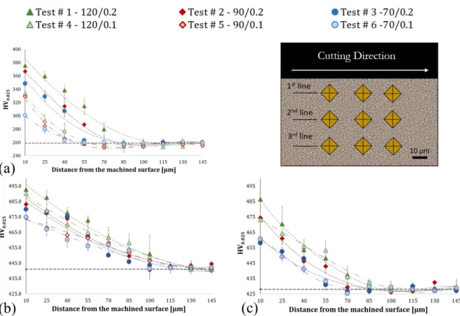
In materials such as Inconel718 due to its applications the hardness and residual stresses are two important factors to consider [16]. Fig. 6 shows the plots of the micro-hardness measured from 10 µm beneath the machined surface through the radial direction inside the samples. The hardness near the surface reached high values and it rapidly decrease to the values measured very far from the AL (AD=260HV0.025, HT=430HV0.025, DA=428HV0.025). As reported in Fig. 5(a) and (d), higher cutting
speed and feed rate enhance the hardness due to the accumulation of residual strain and dislocation density. Moreover, increasing the cutting speed and the feed rate the AL thickness increased (Fig. 6)
1 2 3 4 5 6 7 8 9 10 11 12 13 14 15 16 17 18 19 20 21 22 23 24 25 26 27 28 29 30 31 32 33 34 35 36 37 38 39 40 41 42 43 44 45 46 47 48 49 50 51 52 53 54 55 56 57 58 59 60 61
as also confirmed by the SEM analysis. However, the AL thickness obtained by the hardness profile is higher due to the hardening induced by the machining in the grains beneath the plastically deformed region. The deepest AL thickness was obtained after the manufacturing route AD+HT+M (Fig. 6(b)). In this case, the cutting parameters did not show significant effects in hardness changes as observed in the AD+M samples. The unmachined material showed higher hardness due to the strengthening phase produced by the HT and the highest variation induced by the machining process is approximately 63HV0.025. The most interesting results are represented in Fig. 6(c) (AD+M+DA).
Indeed, the hardness measured is comparable to the AD+HT+M and the variation beneath the machine surface is still evident. The DA treatment enhanced the hardness at high values regardless the cutting parameters used.
Fig. 6. Micro-hardness distribution. (a) AD+M; (b) AD+HT+M and (c) AD+M+DA.
Fig. 7 shows the residual stress measured on the machined surface. The residual stresses in the hoop direction are generally higher to those in the axial direction due to the stronger deformation condition induced by the tool. The AD+M always showed higher and tensile residual stresses due to the absence
1 2 3 4 5 6 7 8 9 10 11 12 13 14 15 16 17 18 19 20 21 22 23 24 25 26 27 28 29 30 31 32 33 34 35 36 37 38 39 40 41 42 43 44 45 46 47 48 49 50 51 52 53 54 55 56 57 58 59 60 61
of the heat treatment that usually contribute to relax the stress state. Although, some compressive stresses are observed when the AD+HT+M routes are performed, the AD+M+DA shows almost in each case very low tensile or even compressive stresses. This result is mainly due to the benefit to perform the heat treatment at the end of the manufacturing process.
Fig. 7. Residual stresses measured on the samples surface.
Concerning the most critical cutting process (120m/min and 0.2mm/rev) the RS were analysed also in depth (Fig. 8). These profiles shows that the thickness of the layer affected by tensile stresses is greater for the AD+M (about 70μm in the hoop direction and 20μm in the axial direction) compared to the AD+HT+M (about 40μm in the hoop direction and absent in the axial direction). It is interesting to note that the AD+HT+M led to significant compressive stresses (almost -600MPa in the axial direction showed in Fig. 8a) although the AD+M+DA allowed to achieve compressive or absent residual stresses after the machining operation (Fig. 8a and Fig. 8b). Although, the fatigue life is not investigated, it is clear that RS and hardness distribution induced by the manufacturing route
1 2 3 4 5 6 7 8 9 10 11 12 13 14 15 16 17 18 19 20 21 22 23 24 25 26 27 28 29 30 31 32 33 34 35 36 37 38 39 40 41 42 43 44 45 46 47 48 49 50 51 52 53 54 55 56 57 58 59 60 61
AD+M+AD can potentially produce benefit effects in terms of fatigue life [17] as well as fatigue crack propagation threshold due to the high degree of work hardening [18].
Fig. 8. Subsurface RSs distribution (120m/min and 0.2mm/rev) a) axial residual stress; b) hop residual stress.
4. Conclusions
The experimental outcomes reported in this paper show the influence of the three hybrid manufacturing routes adopted on the Inconel718. The AD+M led to low surface roughness and high surface hardness although the RS are predominantly tensile (especially in surface). On the contrary the AD+HT+M led to increase the final surface hardness and induce more compressive RS although the machinability is worst because the strengthening face negatively affect the tool life. Finally, the AD+M+DA represented a better manufacturing strategy since the material was machined was
1 2 3 4 5 6 7 8 9 10 11 12 13 14 15 16 17 18 19 20 21 22 23 24 25 26 27 28 29 30 31 32 33 34 35 36 37 38 39 40 41 42 43 44 45 46 47 48 49 50 51 52 53 54 55 56 57 58 59 60 61
machined prior DA (better machinability) that subsequently allowed to preserve the compressive RS as well as high surface roughness.
Acknowledgements
The authors would like to acknowledge the European research project that founded this research. The project belongs to Horizon 2020 research and innovation programme Novel ALL-IN-ONE machines, robots and systems for affordable, worldwide and lifetime Distributed 3D hybrid manufacturing and repair operations (Project ID: 723795).
References
[1] Y. Kakinuma, M. Mori, Y. Oda, T. Mori, M. Kashihara, A. Hansel, M. Fujishima, Influence of Metal Powder Characteristics on Product Quality with Directed Energy Deposition of Inconel 625, CIRP Annals - Manufacturing Technology 65/1 (2016) 209-212.
[2] M. Schmidt, M. Merklein, D. Bourell, D. Dimitrov, T. Hausotte, K. Wegener, et al., Laser based additive manufacturing in industry and academia, CIRP Annals - Manufacturing Technology 66/2 (2017) 561-583.
[3] D. Bourell, J.P. Kruth, M. Leu, G. Levy, D. Rosen, A.M. Beese, A. Clare, Materials for additive manufacturing, CIRP Annals - Manufacturing Technology 66/2 (2017) 659-681.
[4] E. Hosseini, V.A. Popovich, 2019. A review of mechanical properties of additively manufactured Inconel 718, Additive Manufacturing 30, 100877.
1 2 3 4 5 6 7 8 9 10 11 12 13 14 15 16 17 18 19 20 21 22 23 24 25 26 27 28 29 30 31 32 33 34 35 36 37 38 39 40 41 42 43 44 45 46 47 48 49 50 51 52 53 54 55 56 57 58 59 60 61
[5] R. M’Saoubi, D. Axinte, S.L. Soo, C. Nobel, H. Attia, G. Kappmeyer, S. Engin, W.M. Sim, High performance cutting of advanced aerospace alloys and composite materials, CIRP Annals - Manufacturing Technology 64/2 (2015) 557-580.
[6] S.L. Soo, S.A. Khan, D.K. Aspinwall, P. Harden, A.L. Mantle, G. Kappmeyer, D. Pearson, R. M’Saoubi, High speed turning of Inconel 718 using PVD-coated PCBN tools, CIRP Annals - Manufacturing Technology 65/1 (2016) 89-92.
[7] G. Zhu, D. Li, A. Zhang, G. Pi, Y. Tang, The influence of standoff variations on the forming accuracy in laser direct metal deposition, Rapid Prototyping Journal 17/2 (2011) 98-106.
[8] M.R. Mahamood, Laser Metal Deposition Process of Metals, Alloys, and Composite Materials, first ed., Springer, 2018.
[9] SAE International, 2006, Nickel Alloy, Corrosion and Heat-Resistant, Seamless Tubing 72Ni-15.5Cr-0.95Cb-2.5Ti-0.70Al-7.0Fe Vacuum Melted Solution Heat Treated, Precipitation Hardenable to 170 ksi (1172 Mpa) Tensile Strength (AMS5583D), AMS F Corrosion Heat Resistant Alloys Committee.
[10] I.C. Noyan, J.B. Cohen, Residual Stress – Measurement by Diffraction and Interpretation, first ed., Springer, New York, 1987.
[11] H. Javadi, W. Jomaa, V. Songmene, M. Brochu, P. Bocher, Inconel 718 Superalloy Controlled Surface Integrity for Fatigue Produced by Precision Turning, International Journal of Precision Engineering and Manufacturing 20/8 (2019) 1297-1310.
[12] A. Devillez, G. Le Coz, S. Dominiak, D. Dudzinski, Dry machining of Inconel 718, workpiece surface integrity, Journal of Materials Processing Technology 211/10 (2011) 1590-1598.
[13] S.Q. Deng, A. Godfrey, W. Liu, N. Hansen, A gradient nanostructure generated in pure copper by platen friction sliding deformation, Scripta Materialia 117 (2016) 41-45.
1 2 3 4 5 6 7 8 9 10 11 12 13 14 15 16 17 18 19 20 21 22 23 24 25 26 27 28 29 30 31 32 33 34 35 36 37 38 39 40 41 42 43 44 45 46 47 48 49 50 51 52 53 54 55 56 57 58 59 60 61
[14] J.D. Puerta Velásquez, A. Tidu, B. Bolle, P. Chevrier, J.J. Fundenberger, Sub-surface and surface analysis of high speed machined Ti-6Al-4V alloy, Materials Science and Engineering A 527/10 (2010) 2572-2578.
[15] M.N. Gussev, K.J. Leonard, In situ SEM-EBSD analysis of plastic deformation mechanism in neutron-irradiated austenitic steel, Journal of Nuclear Materials 517 (2019) 45-56.
[16] F. Pusavec, H. Hamdi, J. Kopac, I.S. Jawahir, Surface integrity in cryogenic machining of nichel based alloy-Inconel718, Journal of Materials Processing Technology 211/4 (2011) 773-78.
[17] H. Sasahara, The effect on fatigue life of residual stress and surface hardness resulting from different cutting conditions of 0.45%C steel, International Journal of Machine Tools & Manufacture 45 (2005) 131-136.
[18] Y. Hua, L. Zhanqiang, Effects of cutting parameters and tool nose radius on surface roughness and work hardening during dry turning Inconel 718, The International Journal of Advanced Machining Technology 96 (2018) 5-8. 1 2 3 4 5 6 7 8 9 10 11 12 13 14 15 16 17 18 19 20 21 22 23 24 25 26 27 28 29 30 31 32 33 34 35 36 37 38 39 40 41 42 43 44 45 46 47 48 49 50 51 52 53 54 55 56 57 58 59 60 61