UNIVERSITÉ DE SHERBROOKE Faculté de génie
Département de génie chimique et génie biotechnologique
Traitement de solutions contaminées contenant de l'acide
carboxylique par plasma thermique submergé
Treatment of contaminated solution containing carboxylic
acid by submerged thermal plasma
Thèse de doctorat Spécialité: génie chimique
Sanaz Safa
Jury: Gervais Soucy (directeur) Richard Munz
Michèle Heitz Jocelyn Veilleux
À ma famille et mon amour, Mahmood
RÉSUMÉ
La pollution de l'environnement est devenue un problème mondial majeur. Le développement rapide des industries de procédés conduit à une augmentation constante des quantités d'eaux usées et des liqueurs contaminées rejetées. Les acides carboxyliques représentent une part importante de la charge organique des polluants dans les eaux usées et dans les solutions aqueuses industrielles. Une technologie efficace et respectueuse de l'environnement est donc requise pour réduire les effets négatifs de l'industrialisation sur l'environnement et pour éliminer les polluants des eaux usées et des liqueurs industrielles contaminées. Le plasma thermique submergé à courant continu (CC) est l'une des technologies proposées pour éliminer les contaminants des liquides et des solutions. Le réacteur au plasma thermique submergé à courant continu est un nouveau réacteur dans lequel le contact direct entre le plasma et la solution est établi. Une caractéristique importante du plasma thermique type CC est le gaz de plasma. Selon le type du gaz plasmagène, les plasmas thermiques CC présentent différents taux de décomposition, d’espèces réactives, d’enthalpies, de conductivités thermiques, et de temps de vie des électrodes. Parmi les différentes torches des plasmas thermiques CC, la torche à plasma thermique à mélange gazeux à base de CO2, récemment inventée, présente une amélioration très
significative de la performance, c'est-à-dire une enthalpie plasmatique et une conductivité thermique élevées par rapport à celles des gaz de plasma concurrents. Une approche principalement expérimentale a permis d’étudier la faisabilité et le mécanisme de décomposition de l'acide carboxylique à haut poids moléculaire dans des solutions via les différents plasmas thermique submergés à CC. L'acide sébacique, un acide carboxylique à haut poids moléculaire a été choisi comme représentant de contaminant de type organique dans la liqueur Bayer. Deux différentes torches de plasma, incluant la torche à plasma oxygène et air ainsi que la torche à plasma CO2/CH4 nouvellement conçues ont été utilisées. L'effet des différentes conditions de
fonctionnement en incluant le temps de traitement, le pH initial de la solution, et la pression du réacteur, ainsi que le rôle des agents oxydants tels que le H2O2, ont été étudiés sur la
décomposition de l'acide sébacique. Pour identifier le rôle des différents gaz de plasma et des conditions opérationnelles sur le mécanisme de décomposition et sur les produits intermédiaires, une caractérisation qualitative et quantitative a été réalisée sur les solutions traitées avec la méthode de chromatographie ionique couplée à la spectrométrie de masse (IC/MS). L'effet thermochimique des gaz de plasma sur la décomposition de l’acide sébacique et sur les produits intermédiaires a également été étudié. À travers les différents essais réalisés dans cette étude, il a été montré pour la première fois que la décomposition de l'acide carboxylique de poids moléculaire élevé est réalisable avec le plasma thermique submergé en utilisant des gaz de plasmas différents. Le taux de décomposition d'acide sébacique lors de l’utilisation d’un plasma thermique à oxygène en milieu basique est plus élevé par rapport aux autres plasmas thermiques (air, et CO2/CH4) en mode submergé. Il a été constaté que cela est dû principalement à sa forte
l'acide sébacique en milieu basique par l’utilisation de plasma d’oxygène et de plasma à air se produit par un mécanisme d'oxydation consécutif jusqu'à la production finale d'acides di-carboxyliques de plus faibles poids moléculaires et de CO2 (dissous dans la solution sous la
forme de carbone inorganique). Il a été trouvé aussi pour la première fois que le plasma thermique submergé CO2/CH4, peut décomposer l'acide carboxylique de poids moléculaire élevé
sur la base d’un mécanisme séquentiel de photo-oxydation en raison de sa forte intensité de rayonnement ultraviolet. Le plasma de CO2/CH4 a montré une vitesse de décomposition
supérieure dans le milieu neutre. Par contre, en milieu basique, le plasma d'oxygène et le plasma d'air ont montré une vitesse de décomposition plus élevée. Il a également été montré que l'ajout d'H2O2 en milieu basique a augmenté la vitesse de décomposition de l'acide sébacique avec le
plasma CO2/CH4 jusqu’à la même vitesse de décomposition que le plasma d'oxygène dû à une
plus grande intensité de rayonnement UV du plasma de CO2 en comparaison avec celle du
plasma d'oxygène. Dans une perspective plus générale, à travers différentes expériences, il a été montré que le plasma de CO2/CH4 peut offrir une grande vitesse de décomposition des acides
carboxyliques de poids moléculaire élevés dans un milieu acide et neutre, et également en milieu basique en présence de peroxyde d'hydrogène. Cela permettra le traitement des contaminants dans une grande variété de conditions de solution à l'aide de plasma du gaz CO2. Les résultats de
cette thèse aident à mieux comprendre la décomposition des contaminants organiques à hauts poids moléculaires dans les solutions utilisant les plasmas thermiques submergés. De plus, ces résultats proposent une application potentielle pour la torche à plasma de CO2pour le traitement
des eaux usées.
Mots clés : Plasma thermique submergé; dioxyde de carbone, le traitement de la solution aqueuse, l'acide carboxylique; Chromatographie ionique/ Spectrométrie de masse
ABSTRACT
Environmental pollution has become a major global problem. Rapid development of process industries leads to a constant increase in amounts of wastewater and contaminated industrial process liquors. Carboxylic acids represent a significant portion of the organic load of pollutant in wastewater and industrial aqueous solutions. An effective and environmentally friendly technology is therefore required to reduce the negative effects of industrialization on the environment and subsequently remove pollutants from wastewater and contaminated industrial liquors. DC (Direct Current) submerged thermal plasma is one of the proposed technologies for removing contaminants from liquids and solutions. DC submerged thermal plasma reactor is a novel reactor in which the direct contact between plasma and solution is established. An important characteristic of typical DC thermal plasma is the plasma gas. Depending on the type of plasma gas, DC thermal plasmas present different decomposition rates, reactive species, enthalpy, thermal conductivity, and electrode life time. Among different DC thermal plasma torches, the recently invented CO2-based gas mixture thermal plasma torch exhibits a very
significant performance improvement, i.e. high plasma enthalpy and high thermal conductivity in comparison with competing plasma gases. In this study, by a mainly experimental approach, the feasibility and decomposition mechanism of high molecular weight carboxylic acid in solution via different DC submerged thermal plasmas has been investigated. Sebacic acid, a high molecular weight carboxylic acid, was selected as a representative of a typical organic contaminant in Bayer liquor. Two different DC plasma torches have been used including oxygen DC plasma torch and the newly designed CO2/CH4 plasma torch. The effect of different
operational conditions including treatment time, initial solution pH, and the reactor pressure as well as the role of oxidizing agents such as H2O2, were investigated on the decomposition of
sebacic acid. To identify the role of different plasma gases and operational conditions on the decomposition mechanism and its intermediate products, qualitative and quantitative characterization was done on the treated solutions with IC/MS (Ion Chromatography/Mass Spectrometry) method. The thermochemical effect of the plasma gases on the decomposition of sebacic acid and its intermediate products was also investigated. Through different experiments, it was shown for the first time that decomposition of high molecular weight carboxylic acid is feasible with submerged thermal plasma by using different plasma gases. The decomposition rate of sebacic acid by using oxygen thermal plasma in basic medium was higher compared with other thermal plasmas (air, and CO2/CH4) in submerged mode. It was found that the higher
decomposition rate with oxygen plasma is mostly due to its high concentration of oxidant species such as ozone. The decomposition of sebacic acid in basic medium with oxygen and air plasma was revealed to occur with a consecutive oxidation mechanism up to the final production of the lowest molecular weight di-carboxylic acids and CO2 gas (dissolved in solution in the form of
inorganic carbon). It was found for the first time that the CO2/CH4 submerged thermal plasma
can decompose well high molecular weight carboxylic acid based on a sequential photo-oxidation mechanism due to its high ultraviolet (UV) radiation intensity. The CO2/CH4 plasma showed
decomposition rate in basic medium. It was also determined that adding H2O2 in basic medium
increased the sebacic acid decomposition rate with the CO2/CH4 plasma up to the same
decomposition rate of the oxygen plasma due to higher UV radiation intensity of the CO2plasma
than that of the oxygen plasma. In a more general perspective, through different experiments, it was shown that CO2/CH4 plasma can offer high decomposition rate for high molecular weight
carboxylic acids in acidic and neutral medium and also in basic medium in the presence of hydrogen peroxide. This will allow using plasma for treatment of contaminants in a wide variety of solution conditions by using CO2 gas. The findings of this thesis therefore will shed light on
the decomposition of large organic contaminants in solutions with submerged thermal plasmas. Also, it provides a potential application for CO2plasma torch in wastewater treatment.
Key words: Submerged thermal plasma; Carbon dioxide; Aqueous solution treatment; Carboxylic acid; Ion chromatography/ Mass Spectrometry
ACKNOWLEDEGMENTS
First, I would like to express my special appreciation and thanks to my supervisor Prof. Gervais Soucy for the opportunity to work on this project. His support and guidance encouraged me to advance my research and allow me to grow as a research scientist.
I would also like to thank the jury committee for their valuable inputs and support regarding this research.
This work could not have been completed without the help and support of our research group members, Serge Gagnon, and Andre Bilodeau. Special thanks to Carl St-Louis who helped me by developing a characterization method. I would also like to thank Alireza Hekmat-Ardakan for scientific discussions and his contributions in different activities related to this project. My sincerest thanks go to all my past and present lab mates.
I would like to thank my husband, Mahmood, for love and support that he has shown during the past years.
And last but not least, I wish to thank my parents and my sister for their unconditional love and support over these years having been so far away from home.
TABLE OF CONTENTS
RÉSUMÉ...ii
Abstract ...iv
ACKNOWLEDEGMENTS ...vi
List of Figures ... xiii
List of Tables...xix
1 Introduction ...1
1.1 Need for liquid and solution treatment...1
1.2 Submerged thermal plasma ...1
1.3 Project definition and thesis objective ...4
1.4 Original contributions ...5
1.5 Thesis outline ...6
Chapitre 2 ...8
2 Liquid and Solution Treatment by Thermal Plasma: A review ...8
2.1 Abstract ...10
2.2 Introduction ...10
2.2.1 Plasma ...12
2.2.2 Classification of thermal plasma ...13
2.2.3 Effectiveness of thermal plasma technology for waste treatment ...14
2.3 Results and Discussion...16
2.3.1.1 Liquid injection into plasma jet...25
2.3.1.2 Steam DC plasma...31
2.3.1.3 Plasma jet injection into volume of liquid (submerged plasma) ...36
2.3.2 Radio frequency (RF) induction plasma ...42
2.3.3 Thermal plasma patents for liquid and solution treatment ...47
2.4 Summary ...53
2.5 Conclusion...54
2.6 Acknowledgments...56
2.7 References ...56
Chapitre 3 ...63
3 Decomposition of high molecular weight carboxylic acid in aqueous solution by submerged thermal plasma ...63
3.1 Abstract ...66
3.2 Nomenclature ...66
3.3 Introduction ...67
3.4 Material and methods ...69
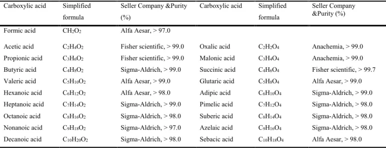
3.4.1 Chemicals...69
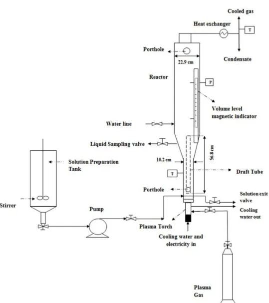
3.4.2 Experimental set-up...70
3.4.3 Procedure...71
3.4.4 Analytical methods...72
3.4.5 Thermodynamic study...73
3.5 Result and discussion ...74
3.5.1 Thermodynamic study...74
3.5.2.2 Effect of plasma gas on sebacic acid decomposition rate ...81
3.5.2.3 Effect of sodium hydroxide (NaOH) concentration on conversion of sebacic acid 83 3.5.3 Reaction mechanism of sebacic acid decomposition ...84
3.5.4 Kinetic study ...86
3.6 Conclusion...92
3.7 Acknowledgments...93
3.8 References ...93
Chapitre 4 ...95
4 Application of a novel CO2DC thermal plasma torch submerged in aqueous solution for treatment of dissolved carboxylic acid...95
4.1 Abstract ...97
4.2 Introduction ...97
4.3 Material and methods ...100
4.3.1 Chemicals...100
4.3.2 CO2/CH4DC thermal plasma torch...101
4.3.3 Experimental set-up...101
4.3.4 UV (Ultraviolet) radiation measurement...104
4.3.5 Procedure...104
4.3.6 Analytical methods...105
4.3.7 Thermodynamic study...106
4.4 Result and discussion ...106
4.4.1 Thermodynamic study...106
4.4.2 Experimental study...110
4.4.2.2 Effect of initial solution pH...112
4.4.2.3 Effect of hydrogen peroxide...120
4.4.2.4 Effect of pressure ...125 4.4.2.5 Reaction mechanism ...128 4.5 Conclusion...130 4.6 Acknowledgments...131 4.7 References ...132 Chaptire 5 ...135
5 Comparison of CO2and oxygen DC submerged thermal plasmas for decomposition of carboxylic acid in aqueous solution ...135
5.1 Abstract ...137
5.2 Introduction ...137
5.3 Material and methods ...139
5.4 Result and discussion ...141
5.4.1 Decomposition vs. treatment time...141
5.4.2 Decomposition rate in the presence of hydrogen peroxide ...142
5.4.3 Decomposition rate at non-atmospheric pressure ...144
5.5 Conclusion...145
5.6 Acknowledgments...146
5.7 References ...146
Chapitre 6 ...147
6 Experimental and thermodynamic comparison between a novel CO2/CH4and an oxygen submerged DC thermal plasma for treatment of sebacic acid in basic aqueous solution ...147
6.1 Abstract ...150
6.2 Introduction ...150
6.3 Material and methods ...153
6.3.1 Chemicals...153
6.3.2 CO2/CH4and oxygen DC thermal plasma torches...153
6.3.3 Experimental set-up and procedure...154
6.3.4 UV (Ultraviolet) radiation measurement...157
6.3.5 Analytical methods...157
6.4 Thermodynamic calculation...158
6.5 Result and discussion ...159
6.5.1 Thermodynamic study...159
6.5.2 Experimental study...165
6.5.2.1 Effect of reaction time...165
6.5.2.2 Effect of hydrogen peroxide...169
6.5.2.3 Effect of pressure ...175
6.5.3 Reaction mechanism ...181
6.6 Conclusion...184
6.7 Acknowledgments...185
6.8 References ...185
7 Conclusion and future work ...188
7.1 Conclusions ...188
7.2 Suggested future work...190
7.3 Conclusion and future work (in French) ...190
7.5 Travaux futurs suggérés ...193 References ...194
LIST OF FIGURES
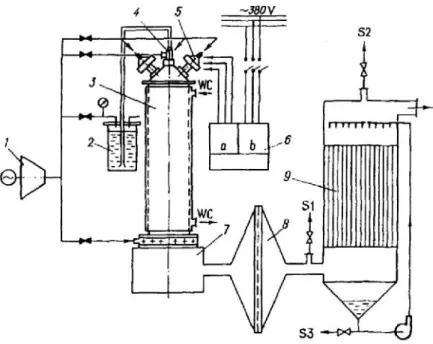
Figure 2.1 Method of generating DC thermal plasma torch): a) transferred arc; b) non-transferred arc [Murphy, 1999] ...17 Figure 2.2 Schematic diagram of the arc jet plasma reactor [Snyder et al., 1996] ...26 Figure 2.3 Schematic drawing of the experimental setup for plasma-thermal processing of toxic waste:1) compressed-air feeding system, 2) liquid-waste feeding system ,3) reactor ,4) atomizer, 5) plasma generators, 6) electrical power sources [Knak et al., 1997] ...28 Figure 2.4 Pyroplasma pyrolysis units developing by Westinghouse [Pfender, 1999]...29 Figure 2.5 Schematic drawing of PLASCON process [Murphy, 1999]...30 Figure 2.6 Schematic diagram of steam plasma system for liquid hazardous waste treatment [Seok-Wan Ki et al., 2003] ...33 Figure 2.7 Schematic drawing of experimental apparatus of DC water plasma [Nishioka et al., 2009]...34 Figure 2.8 Schematic drawing of submerged plasma reactor with draft tube [Munholand et al., 2006]...37 Figure 2.9 Appearance of the experimental reactor for the plasma treatment of aqueous solutions [Samokhin et al., 2010]...40 Figure 2.10 Schematic view of experimental setup [Maehara et al., 2008]...46 Figure 3.1 Schematic drawing of the experimental set-up...71
Figure 3.2 Equilibrium log (mole) of sebacic acid decomposition components as a function of temperature with O2plasma, CSebacic acid= 4.5g/L, CNaOH= 0.75 M, pressure = 308 kPa
...76 Figure 3.3 Comparison of equilibrium log (mole) of sebacic acid decomposition components as a function of temperature with O2 plasma and air plasma, CSebacic acid= 4.5g/L,
CNaOH= 0.75 M, pressure = 308 kPa...77
Figure 3.4 Concentration of observed intermediate products as a function of reaction time during sebacic acid decomposition by submerged thermal plasma, CSebacic acid= 4.5g/L, ,
CNaOH= 0.15 M (pH =12.5) , O2 plasma gas, gas flow rate= 60 L/min, reaction time =
30min...79 Figure 3.5 (a) Effect of plasma gas on the concentration of intermediate products vs. time, CSebacic acid= 4.5g/L, Gas flow rate= 60 L/min, CNaOH= 0.75 M (pH = 13.1). (b)
Magnified zone of location A...80 Figure 3.6 Concentration of intermediate products as a function of sebacic acid conversion, CSebacic acid= 4.5 g/L, CNaOH= 0.15 M (pH = 12.5), O2 as plasma gas, gas flow rate=
60 L/min, reaction time = 30min...81 Figure 3.7 Effect of plasma gas type on the decomposition rate of sebacic acid, gas flow rate= 60 L/min, CNaOH= 0.75 M (pH =13.1) ...83
Figure 3.8 Effect of NaOH concentration on the sebacic acid conversion, C Sebacic acid = 4.5g/L,
gas flow rate= 60 L/min, reaction time = 30min...84 Figure 3.9 Reaction mechanism for sebacic acid decomposition by plasma oxidant species ...85 Figure 3.10 Plot of ln(-ln(l-f)) vs. ln(t) for calculation of kinetic parameters including energy distribution parameter (γ) ...89
Figure 3.11 Comparison of the kinetic model with experiment data for decomposition of sebacic acid by submerged thermal plasma ...91 Figure 3.12 –ln(C/C0) vs. time for sebacic acid decomposition...92
Figure 4.1 (a) Schematic drawing of the experimental set-up. (b) Magnified zone of location A shown in Figure 4.1 (a) with UV probe for plasma radiation measurement...103 Figure 4.2 Comparison of formation of equilibrium log (mole) of species vs. temperature for reaction between CO2/CH4(CO2/CH4=1.875) plasma gas and two solutions with (solid
line) and without (dashed line) sebacic acid, CSebacic acid= 4.5g/L, CNaOH= 0.045 M
(pH=7), atmospheric pressure ...109 Figure 4.3 Sebacic acid concentration and conversion versus treatment time, C Sebacic acid = 4.5g/L,
gas flow rate = 23 L/min, CO2/CH4=1.875, solution pH=7, reaction time = 13.4 min,
reactor pressure = 1 atm (108 kPa)...111 Figure 4.4 (a) Concentration of intermediate products as a function of time, CSebacic acid= 4.5g/L,
solution pH=7, gas flow rate= 23 L/min, CO2/CH4=1.875, reaction time = 13.4 min,
reactor pressure = 1 atm (108 kPa). (b) Magnified zone of location A...112 Figure 4.5 Effect of solution pH on sebacic acid conversion, CSebacic acid= 4.5 g/L, gas flow rate =
23 L/min, CO2/CH4=1.875, reaction time = 13.4 min, reactor pressure = 1 atm
(108 kPa) ...113 Figure 4.6 Effect of solution pH on detected UV emission, CSebacic acid= 4.5 g/L, gas flow rate
= 23 L/min, CO2/CH4=1.875, reactor pressure = 1 atm (108 kPa) ...114
Figure 4.7 (a) Concentration of carbonic acid as a function of sebacic acid conversion, CSebacic acid= 4.5 g/L, gas flow rate= 23 L/min, CO2/CH4=1.875, reaction time = 13.4
Figure 4.8 (a) and (b) Effect of solution pH on concentration of intermediate products as a function of sebacic acid conversion, CSebacic acid= 4.5 g/L, gas flow rate= 23 L/min,
CO2/CH4=1.875, reaction time = 13.4 min, reactor pressure = 1 atm (108 kPa) ...118
Figure 4.9 Effect of adding H2O2 as catalyst on sebacic acid conversion vs. time,
CSebacic acid= 4.5g/L, gas flow rate= 23 L/min, CO2/CH4=1.875, reaction time = 13.4
min, reactor pressure = 1 atm (108 kPa) ...121
Figure 4.10 Effect of adding H2O2 on concentration of, (a) carbonic acid at pH=7, (b) carbonic
acid pH=12.5, (c) other intermediate products pH=7, (d) other intermediate products pH=12.5, (e) magnified zone of location A vs. sebacic acid conversion, C Sebacic acid = 4.5g/L, gas flow rate= 23 L/min, CO2/CH4=1.875, reaction time =
13.4 min, reactor pressure = 1 atm (108 kPa) ...124 Figure 4.11 Effect of reactor pressure on (a) sebacic acid conversion and ( b, c) its intermediate products, CSebacic acid= 4.5g/L, gas flow rate= 23 L/min, CO2/CH4=1.875, reaction time
= 13.4 min, solution pH=12.5 ...128 Figure 5.1 (a) The experimental set-up (b) Magnified zone of location A shown in Figure 5.1(a) with UV probe for plasma radiation measurement ...141 Figure 5.2 Sebacic acid concentration versus treatment time, CSebacic acid= 4.5g/l,
Solution pH=12.5, CO2/CH4=1.875, Reactor pressure = 1 atm (108 kPa). ...142
Figure 5.3 Effect of adding H2O2 as oxidizing agent on sebacic acid concentration vs. time,
CSebacic acid= 4.5g/l, pH=12.5, CO2/CH4=1.875, reactor pressure = 1 atm (108 kPa)..143
Figure 5.4 Effect of reactor pressure on sebacic acid concentration, CSebacic acid= 4.5g/l,
Figure 6.1. a) Schematic drawing of the experimental set-up reactor with UV probe for plasma radiation measurement, b) configuration of CO2/CH4torch, c) configuration of oxygen
torch...156 Figure 6.2 Equilibrium log (mole) of (a) oxygen and (b) CO2/CH4plasma species vs. temperature
at atmospheric pressure ...161 Figure 6.3 Comparison of the formed species at equilibrium condition vs. temperature for reaction between (a) oxygen plasma, (b) CO2/CH4 (CO2/CH4=1.875) plasma gas and
two solutions with (solid line) and without (dashed line) sebacic acid, CSebacic acid= 4.5g/L, CNaOH= 0.15M (pH=12.5) ...163
Figure 6.4 (a) Sebacic acid conversion versus treatment time, (b) Concentration of carbonic acid as a function of sebacic acid conversion, CSebacic acid= 4.5g/l, solution pH=12.5,
CO2/CH4=1.875, reactor pressure = 1 atm (108 kPa) ...166
Figure 6.5 (a) Concentration of intermediate products as a function of sebacic acid conversion, CSebacic acid= 4.5g/l, solution pH=12.5, CO2/CH4=1.875, reactor pressure = 1 atm (108
kPa). (b) Magnified zone of location A...169 Figure 6.6 Effect of adding H2O2 as oxidizing agent on sebacic acid conversion vs. time,
CSebacic acid= 4.5g/l, pH=12.5, CO2/CH4=1.875, reactor pressure = 1 atm (108 kPa).171
Figure 6.7 Effect of adding H2O2 as oxidizing agent on concentration of decomposition products
vs. sebacic acid conversion for oxygen plasma and CO2/CH4 plasma, C Sebacic acid= 4.5g/l, pH=12.5, CO2/CH4=1.875, reactor pressure = 1 atm (108 kPa) ...173
Figure 6.8 (a, b) Comparison between intermediate products concentration with oxygen plasma and CO2/CH4 plasma in the presence of H2O2 vs. sebacic acid conversion, CSebacic acid= 4.5g/l, pH=12.5, CO2/CH4=1.875, reactor pressure = 1 atm (108 kPa). ...175
Figure 6.9 Effect of reactor pressure on sebacic acid conversion, CSebacic acid= 4.5g/l,
CO2/CH4=1.875, solution pH=12.5...176
Figure 6.10 Effect of reactor pressure on concentration of intermediate products vs. sebacic acid conversion for oxygen plasma and CO2/CH4 plasma, CSebacic acid= 4.5g/L,
CO2/CH4=1.875, solution pH=12.5...179
Figure 6.11 (a, c) Comparison between intermediate products concentration with oxygen plasma and CO2/CH4 plasma at non-atmospheric pressure vs. sebacic acid conversion, (b)
LIST OF TABLES
Table 2.1. International Incinerator Dioxins and Furans Emission Regulations ...15
Table 2.2. Hazardous waste incineration emission limits, acid gases and combustion products specified by various justifications (values expressed as mg/Rm3 @11% O 2) (CCME [Canadian Council of Ministers of enviroenment, 1992])...15
Table 2.3. Recent experimental works on arc plasma liquid and solution treatment...18
Table 3.1. Carboxylic acids employed for the calibration curves for IC-MS method. ...73
Table 3.2. Gas species for air and O2as plasma gas at 4000°C ...75
Table 3.3. Kinetic parameters for decomposition of sebacic acid ...90
1 INTRODUCTION
1.1 Need for liquid and solution treatment
In recent years, environmental pollution has become a global problem due to the significant increase in the amount of waste. The organic contaminants are associated with human, industrial, and agricultural wastewaters [Malik et al., 2002]. They enter into the environment through common wastewater pathways. The presence of these contaminants in environment has negative health effects on humans and aquatic organisms [Magureanu et al., 2010]. Moreover the presence of organic contaminants in industrial process liquor has negative effect on production efficiency of some industries including pulp & paper and aluminum industry [Yargeau et al., 2001]. The nature of contaminants is different depending on the application and the raw materials used in the chemical process. A significant amount of pollutants in wastewater of chemical process industries like dyes and pigment, paints, petrochemicals, etc. are carboxylic acids [Gandhi et al., 2012]. Carboxylic acids can also be found in different concentrations in a wide variety of oily wastes. They also form a significant part of organic contaminants in Bayer process liquors in the aluminum industry [Power et al., 2011]. A large amount of solubilised and built up carboxylic acids in the Bayer liquor has negative effects on the production efficiency and increases raw material usage in the aluminum industry [Power et al., 2011]. These pollutants are composed of different numbers of carboxyl groups with the mixture of high and low molecular weight carboxylic acids [Power et al., 2011]. Therefore, treatment of liquid and solutions containing carboxylic acid contaminants has become an important issue to address environmental problems [Safa and Soucy, 2013].
1.2 Submerged thermal plasma
Many efforts have been done to find effective methods for liquid treatment. The ability of treating various types of waste, off-gas and residues composition as well as removal efficiency were considered for choosing the appropriate destruction technique. The environmentally friendly
procedure is an important factor for the treatment processes. In general, there are two conventional methods for waste treatment: landfill disposal and incineration, and both face important challenges. As a result of landfill method, landfill sites become less and less available and waste disposal in oceans lead to major aquatic environmental problems. Although many types of wastes are combustible, incineration has various disadvantages including ash products, generation and release of NOx and dioxin, high off-gas flow rates which requires cleaning,
hazardous residues and disposal obligation [Tomizawa and Tezuka, 2006]. The combustion process requires large air/fuel ratio for decomposition of contaminants. It also requires an additional source of fuel for treating wastes with a low heating value. Moreover, in the case of non-combustible wastes, even high-temperature incineration is not effective; incineration is only able to volatilize these waste materials into gaseous phase and release unconverted toxins to the atmosphere.
Plasma is the fourth state of matter, which contains a mixture of electrons, ions and neutral particles. It can be formed when an electrical current or electromagnetic field passes through a gas. Thermal plasma, one of the different types of plasma, is made from a mixture of electrons, ions and neutral particles, with equal temperature for heavy particles and electrons (Te~Th
=2000-30 000 K) [Gomez et al., 2009]. Among different waste treatment technologies, thermal plasma is significant because it has high energy density, high chemical reactivity, oxidizing and reducing atmospheres, and rapid quenching rate [Heberlein and Murphy, 2008]. These lead to fast reaction rate, high volume of contaminant reduction in most cases and minimum volume of produced gases requiring cleanup [Murphy, 1999]. It also provides the possibility of large throughput in small reactors [Heberlein and Murphy, 2008; Narengerile et al., 2011]. These unique advantages of thermal plasma lead to growing interest in applying thermal plasma reactors for treating contaminated liquids and solutions [Safa and Soucy, 2013]. Due to special characteristics of thermal plasma including high energy density, temperature and chemical reactivity, a good mixing as well as a high heat and mass transfer between the plasma jet and the solution is required for effective contaminants decomposition. Among different types of thermal plasma, submerged plasma was therefore suggested as a novel method in which the direct contact
between plasma and solution was established [Safa and Soucy, 2013; Bernier et al., 2001]. This novel reactor with direct contact between the plasma and the solution was designed for the first time by Bernier et al. [Bernier et al., 2001]. All the previous studies related to the performance of submerged thermal plasma have been carried out on low molecular weight contaminants [Bernier et al., 2001; G. Soucy et al., 2006; Fortin et al., 2000]. These results showed that submerged thermal plasma can decompose low molecular weight contaminants. However, due to inadequate quantitative analytic technique, no data is available on the intermediate products and the reaction mechanisms for treatment by submerged thermal plasma. Furthermore, the performance of submerged thermal plasma on the decomposition of high molecular weight contaminants such as long-chain carboxylic acids, which represents a significant portion of the organic load of wastewater pollutants, has not been investigated yet.
The performance of thermal plasma depends on the plasma gas. Different plasma gases provide different reactive species, enthalpies and thermal conductivities. They also provide different electrode life-times [Safa and Soucy, 2013]. Therefore, different plasma gases can decompose treated materials with different decomposition rates. Air, O2 and nitrogen are considered as
common plasma gases. Recently, the Centre for Advanced Coating Technology, University of Toronto, designed and built a direct current (DC) plasma torch with a graphite cathode which uses carbon-containing molecular gases such as CO2-based gas mixtures as plasma gases. These
gases have some advantages compared to common plasma gases. They can efficiently transfer heat to the treated waste due to their high plasma enthalpy and high thermal conductivity [Chen et al., 2008]. Moreover, they produce a positive carbon ion current, which can deposit on the surface of a negatively charged cathode. This carbon deposition protects the electrode from erosion and increases the electrode life-time. However, the performance of this novel CO2-based
gas mixture plasma torch has not been investigated yet for treatment of contaminated liquids. This thesis therefore aims to determine the feasibility of high molecular weight carboxylic acid decomposition with different DC submerged thermal plasmas, such as common thermal plasmas (oxygen, air), and the newly designed CO2-based gas mixture (CO2/CH4) thermal plasma.
Moreover, a reliable and adequate analytical technique for quantification of carboxylic acid and its decomposition products is presented. The quantification of the decomposition products will lead to understanding of the carboxylic acid decomposition mechanisms with both common and carbon based thermal plasmas. These mechanisms can be used to predict the performance of submerged thermal plasma technology for the treatment of real hazardous and complex organic contaminants in industrial solutions. The general objective in this research is to show the potential of different submerged thermal plasmas for the decomposition of large organic contaminants. In a more general perspective, through different experiments, it will be shown that there is a potential application for CO2-based gas mixture plasma torch for the treatment of
wastewaters.
1.3 Project definition and thesis objective
The principal objective of the current work was to investigate the feasibility of high molecular weight carboxylic acid decomposition with different plasma gases by using a submerged thermal plasma reactor and thereby understanding decomposition mechanisms. The research question can be defined as: What are the reaction mechanisms of the long-chain carboxylic acids decomposition with different DC thermal plasmas?
Due to the complex nature of thermal plasma, an experimental approach was chosen supported by numerical study. For each plasma gas, the probable intermediate products of decomposition process were first obtained by a thermodynamic approach using FactSage software. Then, experimental facilities were developed to further study the decomposition process. Sebacic acid was selected for the investigation of the decomposition process as a representative of high molecular weight organic contaminant in Bayer liquor [Power et al., 2011]. The decomposition of sebacic acid was investigated by using two different direct current (DC) thermal plasma torches working with common plasma gases (air and O2) and a CO2-based gas mixture. Different
operational conditions, such as reactor pressure and initial solution pH as well as adding hydrogen peroxide as an oxidizing agent were also investigated to better understand the
mechanism of sebacic acid decomposition. The intermediate products at different operational conditions were also characterized to propose a better decomposition mechanism.
This work therefore not only shows the ability of different submerged thermal plasmas to decompose large carboxylic acid in aqueous solutions, but also presents their mechanisms of the decomposition process. Moreover, it presents a new application for the CO2/CH4thermal plasma
in wastewater treatment.
1.4 Original contributions
This project is the first work of its type to ever investigate the decomposition of high molecular weight carboxylic acids by different submerged thermal plasmas. Several original contributions of this work can be mentioned as:
High molecular weight carboxylic acid (sebacic acid) was decomposed with submerged thermal plasma by using common plasma gases, such as oxygen and air for the first time. IC/MS (Ion Chromatography/Mass Spectrometry) was also presented for the first time as an adequate and reliable technique for the quantification of intermediate products of decomposition by submerged thermal plasma. It led to the suggestion of a decomposition mechanism of carboxylic acids with submerged thermal plasma by using common plasma gases. It was also observed that both plasma gases (oxygen and air) can decompose sebacic acids. However, oxygen had higher decomposition rate compared with air. It was found that a consecutive oxidation of carboxylic products governs the decomposition mechanism of high molecular weight carboxylic acid. Chapter 3 will focus on this topic.
A novel direct current (DC) plasma torch, operating with a gas mixture consisting of carbon dioxide and hydrocarbon (methane), has been adapted for the first time for the treatment of a solution containing high molecular weight carboxylic acid. The reaction mechanism of sebacic acid decomposition by the novel CO2 plasma torch was also formulated for the first time based
intermediate products. It was found that the decomposition mechanism is mainly related to the absorption of UV radiation by the solution. This work presented, for the first time, an application of a CO2plasma torch for waste solution treatment.
By studying the decomposition of sebacic acid with oxygen thermal plasma and a CO2-based gas
mixture plasma in submerged mode in basic medium and different operational conditions, two different decomposition mechanisms of sebacic acid were identified. It was shown that the decomposition mechanism in the CO2/CH4plasma was mainly due to UV radiation of the plasma
while in the case of the oxygen plasma; it was more attributed to the plasma oxidizing species. Therefore, this work not only showed the difference between the behaviour of these two plasma gases at different operational conditions, but also presented the condition in which these plasmas can provide the same decomposition rate for contaminants in basic solution. This point is discussed in chapter 5 and in more details in chapter 6.
As the overall contribution of this thesis, the decomposition mechanism of high molecular weight carboxylic acids by using submerged thermal plasmas was shown for the first time. This aspect was especially important because the proposed mechanism can be used to predict the performance of this technology for the treatment of real hazardous and complex organic contaminants in industrial aqueous solutions. More importantly, for the first time a potential application of the CO2/CH4 DC thermal plasma torch was presented for the treatment of
contaminated liquids.
1.5 Thesis outline
This thesis includes 7 chapters. State of the art is presented in chapter 2 as a review paper, which covers the available literature on liquid and solution treatment by thermal plasma. It also includes the overall scientific notions required to understand the subsequent chapters.
Chapter 3 covers the results of a thermodynamic and experimental study on sebacic acid decomposition by submerged thermal plasma by using oxygen and air as plasma gases. It
presents IC/MS (Ion Chromatography/Mass Spectrometry) as an adequate method for the quantitative analysis of high and low molecular weight carboxylic acids. Decomposition of sebacic acid with submerged thermal plasma by using a novel DC (Direct current) torch with CO2/CH4 as plasma gas at different operational conditions is studied in chapter 4. As the next
step in chapter 5 and 6, the performance of oxygen DC plasma torch is experimentally and thermodynamically compared with that of a CO2/CH4DC plasma torch in a submerged mode in
basic medium. The performance of both plasmas is evaluated at different operational condition including reactor pressure as well as adding hydrogen peroxide. Lastly, chapter 7 provides conclusions and suggestions for future work.
CHAPITRE 2
2 LIQUID AND SOLUTION TREATMENT BY
THERMAL PLASMA: A REVIEW
Auteurs et affiliation:
Sanaz. Safa: étudiant au doctorat, Université de Sherbrooke, Faculté de génie, Département de génie chimique et génie biotechnologique.
Gervais. Soucy : professeur, Université de Sherbrooke, Faculté de génie, Département de génie chimique et génie biotechnologique.
Date d’acceptation: 22 juillet 2013
État de l’acceptation: version finale publiée
Revue: International Journal of Environmental Science and Technology Référence: [Safa and Soucy, 2013]
Titre français: Traitement de liquide et solution par plasma thermique: une recension
Contribution au document: This article is the state of the art of this thesis. It covers available
literature on liquid and solution treatment by thermal plasma. It also includes the overall scientific notions required to understand the subsequent chapters. All works of this article were performed by Sanaz Safa under the direction and supervision of Pr. Gervais Soucy.
Résumé français :
Au cours des deux dernières décennies, de nombreuses technologies et approches ont été développées pour le traitement des contaminants dans des liquides et des solutions. Le plasma thermique est une de ces techniques qui a montré une cinétique rapide et une grande efficacité. Cela est dû aux très hautes températures et aux radicaux très actifs utilisés par cette technologie. Par conséquent, l'utilisation du plasma thermique pour le traitement des contaminants dans des liquides et des solutions a suscité beaucoup d’attention, puisque cette technologie a peu d’impacts environnementaux. Cette revue de littérature décrit l’état actuel en matière de traitement des liquides et des solutions par l’exploitation du plasma thermique. En effet, une analyse exhaustive des avancées scientifiques et techniques sur le traitement du liquide et de la solution par le plasma est réalisée, en présentant le traitement de divers contaminants via les différents types de plasmas thermiques. Les principes de génération de plasma thermique et les technologies de plasmas disponibles ayant des applications potentielles pour la génération de produits de haute valeur ajoutée à partir des déchets liquides sont exposés. Finalement, les résultats obtenus par les procédés de plasma thermique pour le traitement de contaminants bien spécifiques sont aussi analysés dans cette revue. À la lumière de la littérature étudiée, on peut conclure que le plasma thermique a un potentiel significatif de traitement des déchets liquides.
2.1 Abstract
During two last decades, numerous technologies and approaches are presented for treating contaminants in liquids and solutions. Among them, thermal plasma has shown rapid kinetic and high destruction efficiencies due to very high temperature and highly active radicals. Hence, the use of thermal plasma for treatment of the contaminants in liquids and solutions has received a lot of attention in view of its low environmental impacts. This review focuses on thermal plasma and it describes the current status of liquid and solution treatment using this technology. A comprehensive analysis of the available scientific and technical literature on liquid and solution plasma treatment is presented, including the treatment of a variety of contaminants in liquids and solutions via different kinds of thermal plasma. The principles of thermal plasma generation and the available plasma technologies with potential applications to generate valuable products from liquid waste are presented. In addition, the results of the thermal plasma processes for the treatment of specific contaminants are investigated. In light of the investigated literature, thermal plasma is found to have a significant potential to treat the liquid wastes.
2.2 Introduction
In the last 50 years, environmental pollution has become a global problem due to the significant increase in amount of waste. A huge amount of contamination is produced from industrial processes [Malik et al., 2002]. The release of these contaminants in the environment from wastewater effluents can have potential health effects on humans and may also affect aquatic organisms in an unpredictable way [Magureanu et al., 2010; Malakootian et al., 2011]. Moreover, the presence of a significant amount of organic contaminants in aqueous solution causes many difficulties in some industries such as pulp & paper and aluminum industry [Yargeau et al., 2001; Onundi et al., 2011]. Therefore, liquid and solution treatments have become an important issue. Many efforts have been done to find effective methods for liquids treatment. Ability of treating a variety of waste types, off-gas and residues composition as well as removal efficiency should be considered for choosing the appropriate destruction technique. Environmental friendly procedure
is also an important factor for treatment processes. Polluting environment by by-product such as ozone depleting-gas, greenhouse effect gases or dioxins is also a serious issue for the treatment techniques.
Several techniques have been proposed for treating contaminants in liquid such as incineration and different types of plasma [Tomizawa and Tezuka, 2006; Deegan et al., 2011]. Due to combustibility of many types of waste, incineration has been used for reduction of waste. However, incineration suffers from various disadvantages including ash products, generation and release of NOxand dioxin, high off-gas flow rates, need for cleaning off-gas, hazardous residues
and disposal obligation. Combustion process requires large air/fuel ratio for decomposition of contaminants. For treating wastes with a low heating value additional source of fuel is required. Moreover, in the case of non-combustible wastes, even high-temperature incineration is not effective. Incineration is only able to volatilize these waste materials into gaseous phase and release unconverted toxins to the atmosphere. Also, landfills only transfer these pollutants from one phase to another. Accordingly, liquid waste especially liquid hazardous wastes, such as PCBs, paint solvents, and cleaning agents are rapidly becoming an environmental threat due to their persistence and inertness. For such kinds of wastes, thermal plasmas can be a good treatment option. Moreover, it offers distinctive advantages including high enthalpy to enhance reaction kinetic, high chemical reactivity, oxidation and reduction atmosphere and rapid quenching rate which lead to [Murphy, 1999]:
High volume reduction in most case
A minimum volume of gaseous products requiring cleanup Low exhaust gas flow rates
Low requiring gas flow Fast start-up and shut-down Small reactor
Therefore, plasma treatment can be used for treating waste where either landfill is difficult, destruction with incineration requires treatment of the off-gas, or emission standard is stringent. The large number of research articles published during the two last decades on treating contaminants in liquid and solution by plasma emphasizes the increasing interest in this particular application of plasma. This work will briefly review different types of thermal plasma and will summarize current status of research on liquid treatment via different kinds of thermal plasma. Available scientific and technical literatures will be analyzed and the results of thermal plasma treatment of some specific contaminants will be presented. This review was performed during 2011-2012 at Department of chemical engineering and biotechnological engineering, Université de Sherbrooke, Canada.
2.2.1 Plasma
In 1879, Sir William Crookes identified Plasma for the first time in a Crookes tube, and he called it "radiant matter", the latter was modified to "plasma" in 1928 by Irving Langmuir [Langmiur, 1928].
Plasma is considered to be the fourth state of matter. It contains a mixture of electrons, ions and neutral particles. In plasma technology, an electrical current or electromagnetic field passing through the gas will generate the plasma. When sufficient number of charge carriers (such as electrons) is generated, the electrical breakdown of the gas occurs. The collision between the generated electrons and gas molecules can lead to the formation of ions, excited species, atoms and photons [Boulos et al., 1994]. In this state, high concentration of free electrons causes plasma to become highly electrically conductive [Moustakas et al., 2005]. A number of gases can be used for the plasma including argon, hydrogen, helium, nitrogen, oxygen, air, steam, CO and CO2. The availability and contribution to desired chemical reactions are the characteristics for
selection of plasma gas. Argon and N2 are normally used for plasma generation. In processes
Plasma is classified by pressure, temperature and electron densities. There are two main types of plasmas: atmospheric pressure and low pressure [Kong, 2006]. Atmospheric-pressure plasmas are divided in two main groups: thermal plasma and non-thermal plasma. In non-thermal plasma Te>> Th~300-400 K and ne~1010m-3 (Te = electron temperature; Th= neutral particle
temperature; ne= Electron density). However, in thermal plasma Te~Th=2 000- 30 000 K and ne
≥1020 m-3. Therefore, thermal plasmas are characterized by a high-energy density and the
identical temperature of heavy particles and electrons [Gomez et al., 2009].
In the following, the characteristics of thermal plasma will be elaborated in more details.
2.2.2 Classification of thermal plasma
Thermal plasma has shown unique advantages for treating aqueous solutions. It has both high energy density and temperature which leads to fast reaction, high heat flux which allow rapid start- up and shut-down times and rapid quenching to produce non-equilibrium chemical compositions. It provides the possibility of a large throughput in small reactor. Moreover, it can provide oxidation and reduction atmospheres in accordance with required chemical reactions and the ability to destroy any kind of chemical bonds [Heberlein and Murphy, 2008; Narengerile et al., 2011]. Due to these advantages, it is not surprising that thermal plasma has been proposed as a green technology for treating aqueous solution during the past several years.
Thermal plasma can be produced by [Murphy, 1999]:
1. Direct current (DC) or alternating current (AC) electrical arc torch 2. Radio frequency induction(RF)
3. Microwave discharge plasma(MW)
Among these, DC arc plasma and Radio frequency have been mostly applied for aqueous solutions treatment. In the following sections, all these technologies will be discussed.
2.2.3 Effectiveness of thermal plasma technology for waste treatment
Effectiveness of waste treatment by thermal plasma can be evaluated by different factors such as destruction and removal efficiency (DRE), the composition of by-product and emission level of undesirable environmental products like dioxins, furans, etc. Process efficiency shows the ability of a technology to destroy wastes in a consistent way with environmental regulations. Destruction is typically evaluated by using a concept which initially was established under the Resource Conservation and Recovery Act (RCRA), known as destruction and removal efficiency (DRE). DRE is defined as the difference between the amount of chemicals going into a process and the amount that is sent out to atmosphere after off-gas treatment. For most organic components, the RCRA regulations require a DRE of 99.99% (otherwise known as four nines). However, for some component groups, such as dioxins and furans, a DRE of 99.9999 % (six nines) is required. However, the DRE of 99.9999 % has become an informal basis for comparison of chemical agent destruction processes.
The emission limits of environmental undesirable products vary for different applications in different parts of the world and for different industries. These limits evaluate technologies from an environmental point of view. Also, they show the ability of treatment technology for destruction of hard to destroy wastes like dioxins. Emission limit of some of hazardous components and incineration products according to CCME (Canadian Council of Ministers of Environment [Canadian Council of Ministers of enviroenment, 1992]) specified by various justifications are presented in Table 2.1 and Table 2.2 [Chandler and Asscociates Ltd., 2006]. These limits originally established for incineration processes, can also be used to evaluate plasma technology:
Table 2.1. International Incinerator Dioxins and Furans Emission Regulations [pg I-TEQ/Rm3@ 11% O2]
Country Incinerator Type Emission limit Comments
EU (European Union) All 92
-CWS(Canada Wide Standards) All 80 (0.08 ng/Rm3) All new construction after 2001, existing
facilities limited to 100 pg ITEQ/Rm3
United States (EPA) Hazardous waste 140
-Australian &New Zealand All 92
-Japan 92 – 4 600 existing facilities have limit of 920-9 200
Rm3= dry Reference cubic meter (at 25oC, 101.3 kPa and 11% O2), TEQ= toxic equivalent quantity, I-TEQ/Rm3=
international toxicity equivalents (the toxicity equivalence factors recommended by the North Atlantic Treaty Organizations’s Committee on Challenges to Modern Society (NATO/CCMS) in 1989 and adopted by Canada in 1990) to 2,3,7,8 tetrachloro dibenzo-p-dioxin per reference cubic meter at 25o C and 101.3 kPa pressure.
Concentrations are corrected to 11 percent oxygen and zero percent moisture (dry).
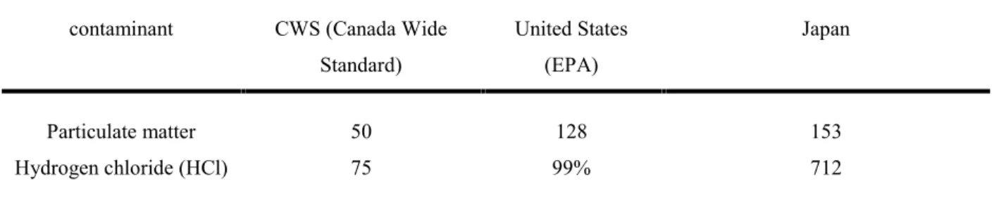
Table 2.2. Hazardous waste incineration emission limits, acid gases and combustion products specified by various justifications (values expressed as mg/Rm3@11% O2) (CCME [Canadian
Council of Ministers of enviroenment, 1992])
contaminant CWS (Canada Wide Standard) United States (EPA) Japan Particulate matter 50 128 153 Hydrogen chloride (HCl) 75 99% 712
According to above data, the dioxins and furans numeric targets in the CWS are more stringent than those in the other part of the world. Using the above data, the emission levels of hazardous waste below the incineration limits will be used for specifying effectiveness of thermal plasma technology for waste treatment.
2.3 Results and Discussion
2.3.1 DC plasma torch for treating contaminants in liquid and solutions
DC arc discharge presents high energy density and high temperature between two electrodes [Huang et Tang, 2007]. Most DC arc torches have three main components including cathode, plasma-forming gas injection stage and anode. Arc torches and electrodes are usually water cooled. Plasma, in the form of high enthalpy jet can be produced above one of the electrodes. The arc generated plasma can be divided in three categories:
1. Transferred arc (Figure 2.1a). One of the electrodes can be the treated material and is placed in an electrically grounded metallic vessel. Therefore, an electrical conductive material should be chosen as reacting material.
2. Non-transferred arc (Figure 2.1b). There are two electrodes in this plasma which do not participate in the processing and have the sole function of plasma generation [Huang and Tang, 2007].
3. Twin torch. It contains two torches. One of the torches serves as the anode and other serves as the cathode. This kind of torch can either work in transferred mode or non-transferred mode [Heberlein and Murphy, 2008].
Figure 2.1 Method of generating DC thermal plasma torch): a) transferred arc; b) non-transferred arc [Murphy, 1999]
Among these three kinds of torch, transferred arc plasma generates high temperature. But, it has the disadvantage of not being able to treat non-conducting materials. The twin-arc can operate in transferred and non-transferred mode. It works as transferred arc when the current flow goes from one electrode to the charge and from the charge to the other torch. Also, it can work in non-transferred arc mode when the current goes form one electrode directly to another electrode. The twin torch generates high temperature and also can treat non-conducting materials like medical waste due to its high temperature arc column. However, control of its arc mode is not easy and it has lower heating efficiency compared to single torch [Iwao et al., 2005].
Non-transferred arc can treat non-conducting materials and offers simpler mechanical control requirements compared to transfer type torches. Moreover, it provides great bulk gas heating capability, high arc stability, especially during the heat up period, simple reactor design, and great overall system reliability [Capote et al., 2007]. A non-transferred type torch can be used for treating waste with high organic concentration. Non-transferred arc processes are chosen for treatment of liquids due to having more uniform temperature distribution and the availability of reactive species.
Researchers began using plasma arc as a technology that could be used to destroy industrial wastes in 1980. The objective was to reach effective degradation with high removal efficiency, low by-product formation and low energy consumption. Also, such unit should be operated with minimum investment and minimum interface with industrial efficiency and output. An overview of these research activities since early 1990s, are given in Table 2.3.
Table 2.3. Recent experimental works on arc plasma liquid and solution treatment Type of plasma, type of liquid
and treatment reaction Type of reactor, condition and treatment results Ref.
liquid injection into the plasma jet
Electrical-arc plasma, laboratory scale , real hazardous liquid
Reactor: plasma unit with a straight-through reactor Plasma torch power:5-17 kW
Plasma gas: air, steam
Plasma gas flow rate : air: 0.7-1.6 m3/h or steam:1.5-2.0 kg/h
Waste feeding rate :0.2-1.8 kg/h
liquid sample: mixture containing cyclohexane Destruction and removal efficiency: n/a ( not available)
Energy consumption: 9.4 kWh/kg ( for 1.8 kg/h feeding rate and 17kW plasma power)
Destruction and removal result: chlorine-containing compounds in exhaust gases does not exceed 0.5 ng/m3 *
[Knak et al., 1997]
DC plasma torch, laboratory scale ,test liquid ,pyrolysis of organic
Reactor: Tube reactor with counter flow liquid injection plasma Plasma torch power:40 V *500A= 20 kW
Sample time :1 h Plasma gas: air
Plasma gas flow rate : 1 440 m3/h
Atomizing gas flow rate (O2): 720 m3/h
Waste feeding rate : 52 kg/h
Liquid sample: benzene and carbon tetrachloride, which were used as stimulants of PCBs.
Destruction and removal efficiency (DRE): 99.99986% Energy consumption:0.38 kWh/m3
Non-transferred AC plasma, torch laboratory scale, test liquid,
thermal oxidation
Reactor: A commercial arc welding supply is used to power the plasma torch in a cylinder reactor.
Plasma gas: Argon with addition oxygen Liquid sample: Acetone.
Waste feeding rate:0-158 kg/h Energy consumption: n/a
Optimizing parameters for increasing destruction efficiency are:
Increasing the current > 50 A; Argon flow rates should be less than 1.1 Nm3/hr; Oxygen injection (DE> 99 %).
[Snyder et al., 1996]
DC non-transferred plasma arc, laboratory scale, test liquid,
photochemical dissociation
Plasma torch power:1.5 kW Plasma gas: Argon
Plasma gas flow rate : 1 050 m3/h
Waste feeding rate: 150 kg/h
Liquid sample: liquid 1,2 dichloroethane as a hazardous liquid Destruction and removal efficiency: n/a
Conversion: 0.98 at injecting point (10 mm the center axis of the plasma jet)
Energy consumption:12.5 kWh/m3
[Snyder and Fleddermann,
1997]
Three electric arc plasma, laboratory scale, real hazardous liquid, oxidation (high temperature
combustion)
Plasma reactor with three-jet mixing chamber Plasma torch power: 28-40 kW
Plasma gas: Air
Plasma gas flow rate: 22.5-31.7 kg/h Waste feeding rate :3.6 kg/h
liquid sample: chlorine-containing waste (aqueous solution) Energy consumption:11.1 kWh/kg (at 40kW plasma power) Result: gases phase sample chlorine in pure form is not detected
[Knak et al., 1997] Plasma torch power :94-120 (82-108) kW
Plasma gas flow rate: 16.9-21.6 kg/h
Waste feeding rate :1-15.5 (5.6-12.5)*10-3kg/h
Liquid sample: 25 % concentration of bromine- phenols containing waste in aqueous solution (and 75% solution waste in a polar organic solvent).
Destruction and removal efficiency: n/a
Energy consumption: 8.64*103 kWh/kg ( plasma power 108 kW
and 12.5 g/h)
Non-transferred arc plasma torch, industrial–relevant scale, real
hazardous liquid
Plasma reactor :PLASCONTMsystem
Plasma torch power: 150 kW Plasma gas: Argon
Liquid sample: organic liquid containing dichlorophenols, dioxin, and other organic species.
Destruction and removal efficiency: 99.9999% Energy consumption: n/a
Dioxin and furan emission: less than 0.01 ng m-3toxic equivalent
[Murphy, 1999]
DC cascade plasma torch, laboratory scale, test liquid
Plasma Torch power: 1-5 kW Waste Feeding rate : 0.015-0.35 kg/h liquid sample: hydrocarbon solution
Destruction and removal efficiency (DRE): n/a Energy consumption:14.4 kWh/kg ( for 0.35 kg/h)
[Pacheco et al., 2001]
Steam DC Plasma
DC non-transferred steam (H2O)
plasma, real hazardous liquid, gasification
Plasma reactor : Steam plasma (circular reactor of vertical type)
Plasma torch power:100 kW Plasma gas: steam
Plasma gas flow rate:: 9.4-10.1 kg/h Sample feeding rate : 68.4 kg/h
Liquid sample: the treatment of liquid hazardous waste such as PCBs, chlorinated solvent wastes, pesticide wastes, and so on (PCB is a mixture of 57% trichlorobiphenyl (C12H7Cl3) and 43%
tetrachlorobiphenyl (C12H6Cl4))
Destruction and removal efficiency (DRE): 99.9999% Energy consumption:1.5 kWh/kg
Dioxin and furan emission: 0.056 ng m-3toxic equivalent
Plasma reactor : water-soluble organic compounds pass through the discharge region of the water plasma
Plasma torch power: 0.91–1.05 kW
Plasma gas: 100% steam and methanol and ethanol were mixed with water for plasma supporting gas.
Plasma gas flow rate: Plasma gas flow rate increases with increasing alcohol concentration because of increasing vapor pressure. Higher vapor pressure of the methanol solution causes larger feed rate of the plasma supporting gas evaporated from the methanol solution.
liquid sample: Methanol or ethanol used as a model substance of water-soluble organic compounds
Destruction and removal efficiency (DRE): n/a Energy consumption: n/a
[Nishioka et al., 2009]
DC non-transferred arc plasma torch (DC water plasma), laboratory scale, test liquid,
pyrolysis and combustion ,chemical oxidation or reduction
Plasma reactor : DC water plasma Plasma torch power: 0.91 kW Plasma gas: steam
Aqueous solution: aqueous phenol solution (5.23* 10-3-52.8*10 -3
kg/m3)
Feed rate of phenol : 5.76*10-4-6.12*10-3kg/m3
The removal efficiency of total organic carbon(TOC): 99.7% Destruction and removal efficiency (DRE): 99.68% Energy consumption: 0.58*106-5.26*106kWh/kg
Product: CO and CO2CH4and C2H2
[Yuan et al., 2010]
Plasma reactor : DC water plasma at atmospheric pressure
Plasma torch power: 1.08 kW Plasma gas: no chemicals additive
Liquid sample: high concentration of phenol solution (1 mol%)
The phenol decomposition rate: 98.2–99.99% (at arc currents 6–8 A.)
Destruction and removal efficiency: 99.9999% Energy consumption: n/a
Plasma reactor: DC water plasma at atmospheric pressure Plasma torch power: 0.66–0.91 kW
Plasma gas: steam
Aqueous solution: aqueous acetone Working pressure: atmospheric pressure
Destruction and removal efficiency: 99.8% (at an arc current of 7 A) Energy efficiency:1.7*10-7mol/J
Energy consumption: 28.1 kWh/kg
[Narengerile and Watanabe,
2012]
DC non-transferred arc plasma torch (DC water plasma), laboratory scale, test liquid
Plasma reactor : water thermal plasma Plasma torch power: less than 1 kW Plasma gas: steam
Liquid sample: 1-decanol emulsion, 1-butanol Destruction and removal efficiency: 99.9999% Energy consumption: n/a
[Choi and Watanabe, 2012]
Plasma jet injection into volume of liquid (submerged plasma)
DC non-transferred plasma torch, pilot plant, test liquid, Thermal
hydrolysis
Plasma reactor: submerged plasma torch with internal recirculation by draft tube
Plasma Torch power: 10-24kW
Plasma gas: argon (low power plasma) and Ar/N2(high power)
Waste volume : 20 m3
Liquid sample: free and complex cyanides in solution Destruction and removal efficiency: n/a
Energy consumption: 1kWh/m3
Results: The higher rate of cyanide destruction compare to thermal hydrolysis occurring in a plug flow reactor.
Product: mostly H2O and CO2
[Fortin et al., 2000]
Plasma reactor : submerged plasma reactor with internal recirculation by draft tube
Plasma torch power:45 kW Plasma gas: Air or O2
Waste Feed concentration: 0.42 mol/m3
Liquid sample: formic acid (black liquor lignin) Treatment time: 20 min
Destruction and removal efficiency (DRE): n/a Energy consumption: n/a
Plasma reactor : submerged plasma reactor with internal recirculation by draft tube
Plasma torch power:100 kW Plasma gas: Air
Volume of liquid:15-20 m3
Waste Feed concentration : 8.3* 10-3kg/m3 (for six organic acid)
Liquid sample: synthetic Bayer liquor (contains six organic acid such as : Salicylic acid, Mesaconic acid, Methylsuccinic acid, Adipic acid, Isophthalic acid, Lactic acid)
Treatment time: 23 min
Destruction and removal efficiency (DRE): n/a Energy consumption:1.9 kWh/m3
[Soucy et al., 2006]
Plasma reactor : submerged plasma reactor with internal recirculation by draft tube
Plasma torch power:40 kW Plasma gas: Oxygen (Air) Plasma gas flow rate: 1 358 m3/h
Liquid sample: Bayer spent evaporated liquor Treatment time:25 min
Destruction and removal efficiency (DRE): n/a Energy consumption: n/a
[Armstrong and Soucy,
2007]
Non-transferred arc plasma torch, laboratory scale , test
liquid, gasification
Plasma reactor : submerged Plasma reactor Plasma torch power:4-30 kW
Plasma gas: argon and oxygen(Argon + hydrogen)
Plasma gas flow rate: 900 m3/h argon and 180 m3/h oxygen
Solution volume: 15 m3
Aqueous solution: decontamination of solutions contaminated by dye molecules (methylene blue) and chlorinated molecules (chlorophenol). Domestic sewage sluge and a steel industry effluent
Treatment time: 40 min
Destruction and removal efficiency (DRE): 45% Energy consumption: 0.22 kWh/m3
DC non-transferred arc plasma torch, laboratory scale, test
liquid, oxidation
Plasma reactor : under water thermal plasma Plasma torch power: 50 kW
Plasma gas: oxygen
Plasma gas flow rate: 108*102Nm3/h (at the anode)
Liquid sample: tributylphosphate (TBP)/dodecane, Perfluoropolyether oil, Trichloroethylene(TCE) Sample flow rate: 0.004 m3/h
Destruction and removal efficiency: better than 99.97 % Energy consumption: n/a
Torch efficiency: 62%
[Mabrouk et al., 2012]
DC plasma torch, laboratory scale, test liquid, high speed
oxidizing
Plasma reactor: a reactor with a water-cooling jacket Plasma torch power: 20 kW
Plasma gas: O2–Ar mixture,( O2-N2)
Plasma gas flow rate: 0.6–0.7 sm3/h
Aqueous solution: aqueous solutions of phenol and humic acids Waste concentration : 15–750*10-6kg/m3
Treatment time: 8–45 min
Destruction and removal efficiency: 80% Energy consumption: n/a
Enthalpy of the plasma:1.2-2.9 kWh/m3(5-9.2 kWh/m3)
[Samokhin et al., 2010]
* In 1988 a CCME predecessor issued a report concerning the anticipated performance of waste incinerators. Shortly thereafter a similar document related to hazardous waste incinerators was issued. While the initial report stopped short of defining a regulatory limit for emissions from waste incinerators, based upon data available at the time, it suggested that well operated facilities should be able to limit PCDD/F emissions to 0.5 ng TEQ/Rm3@ 11%O2. The location and process of feed introduction are quite important for having effective interaction and well mixing between plasma jet and solution. The above technologies use two overall different methods for making the interaction between plasma and solution feed:
1. Solution injection into the plasma jet
2. Plasma jet injection into volume of solution (submerged plasma)
These two injection methods will lead to different energy efficiency. Another important factor in thermal plasma technology is the plasma gas. Air, O2, argon and nitrogen are mostly used as
![Figure 2.1 Method of generating DC thermal plasma torch): a) transferred arc; b) non-transferred arc [Murphy, 1999]](https://thumb-eu.123doks.com/thumbv2/123doknet/5989610.148975/37.918.258.643.143.441/figure-method-generating-thermal-plasma-transferred-transferred-murphy.webp)
![Figure 2.6 Schematic diagram of steam plasma system for liquid hazardous waste treatment [Seok-Wan Ki et al., 2003]](https://thumb-eu.123doks.com/thumbv2/123doknet/5989610.148975/53.918.237.632.132.494/figure-schematic-diagram-steam-plasma-liquid-hazardous-treatment.webp)
![Figure 2.7 Schematic drawing of experimental apparatus of DC water plasma [Nishioka et al., 2009]](https://thumb-eu.123doks.com/thumbv2/123doknet/5989610.148975/54.918.290.626.417.727/figure-schematic-drawing-experimental-apparatus-water-plasma-nishioka.webp)
![Figure 2.8 Schematic drawing of submerged plasma reactor with draft tube [Munholand et al., 2006]](https://thumb-eu.123doks.com/thumbv2/123doknet/5989610.148975/57.918.328.611.199.593/figure-schematic-drawing-submerged-plasma-reactor-draft-munholand.webp)
![Figure 2.9 Appearance of the experimental reactor for the plasma treatment of aqueous solutions [Samokhin et al., 2010]](https://thumb-eu.123doks.com/thumbv2/123doknet/5989610.148975/60.918.253.593.131.512/figure-appearance-experimental-reactor-treatment-aqueous-solutions-samokhin.webp)
![Figure 2.10 Schematic view of experimental setup [Maehara et al., 2008]](https://thumb-eu.123doks.com/thumbv2/123doknet/5989610.148975/66.918.234.637.373.643/figure-schematic-view-experimental-setup-maehara-et-al.webp)