OATAO is an open access repository that collects the work of Toulouse
researchers and makes it freely available over the web where possible
Any correspondence concerning this service should be sent
to the repository administrator:
[email protected]
This is an author’s version published in:
http://oatao.univ-toulouse.fr/23914
To cite this version:
Jońca, Justyna Elżbieta and Malard, Benoît and Soulié, Jérémy and
Sanviemvongsak, Tom
and Selezneff, Serge and Vande Put, Aurélie
Oxidation behaviour of a CoNiCrAlY/h-BN based abradable coating. (2019)
Corrosion Science, 153. 170-177. ISSN 0010-938X
Oxidation behaviour of a CoNiCrAlY/h-BN based abradable coating
Justyna Jonca
a, Benoît Malard
a, Jeremy Souli
é
8, Tom Sanviemvongsak
a, Serge Selezne
ff>
,
Aurelie Vande
Pu
t'
•
*
• ClRIMA T, Un1"'1'Slti de Toulouse, CNRS, fNP. ENSIACET 4 allée Emile Monso • BP44362, 31030 Toulouse cedex 4, Pronœ
b Sofran Aircrqft Englnes, Sttt de Corbdl, rouu Henri Auguste Desbruères, BP81, 91003 EVRY cedex, France
A RTICLE INFO ABST R A CT
Keywords:
CoNfCrAIY/h-BN coatlng Abradable coatlngs Thennally grown oxfdes
High temperature oxfdatfon resfstance
The oxidation resistance of a therrnally sprayed CoNiCrAlY/h-BN abradable coating was studied at 750 and 900 •c. First, the high porosity of the abradable coating was carefully characterised in order to estimate the specific surface area of the coating, required to evaluate the oxidation kinetics. Then the forrned oxides were investigated by XRD, Raman spectroscopy and SEM. At 900
•c,
the mass variations exhibited a deviation from parabolic behaviour due to rapidly growing oxides. Meanwhile, at 750•c,
after a transient state, the oxidation rate reaches a steady state, indicating that a protective alumina scale was maintained at this temperature.1. Introduction
Abradable coatings are designed to preferentially wear out when in contact with a moving surface. For airerait turbines, thermally sprayed coatings are preferred and used for gas path clearance control [1). The clearance at the gas seal locations has a significant influence on the engine efficiency and therefore on the fuel consumption. Ideally, gas turbine engines would be produced with minimal clearance in the gas seal locations. However, these clearances are much larger to allow operation without catastrophic interaction between the rotor and the casing. Abradable coatings minimize these clearances without the risk of catastrophic failure.
Among many MCrAlY (where M = Ni and/or Co) abradable coat ings, CoNiCrAlY showed improved oxidation and corrosion resistance up to 750•c [2). The microstructure of this coating exhibits three main phases, y, y' and Jl The y phase is a solid solution of Co, Ni, Cr and Al with a face centered cubic (FCC) structure [3). The y' Ni3Al is a co herently precipitating phase with a face centered cubic (FCC) structure
[ 4). � is an intermetallic (Co,Ni)Al phase with a body centered cubic (BCC) structure [5). Since the CoNiCrAlY matrix is harder than any of the rubbing blade materials, its abradability is ensured by the presence of macroporosity [2,6). Porosity, in turn, is controlled through the amount of polyester that is thermally sprayed as a part of the coating and later removed by heat treatment after deposition. The abradability can be further improved by addition of solid lubricant, such as hex agonal boron nitride (h BN) [2), which has been found to be very stable at high temperatures up to 1ooo•c [7).
Although few publications about oxidation behaviour of CoNiCrAlY • Corresponding author.
E-mail address: Aurelie.Rouaix@ensiacetfr (A. Vande Put).
abradable coatings have been published [6,8,9), a lot of researchers are investigating these as bond coatings for thermal barrier coating (TBC) systems. The specific composition of these coatings favours the forma tion of a thermally stable, adherent, continuous and slow growing layer of a Al2O3 at high temperatures [10 13). However, the oxide scales on CoNiCrAlY coatings are not pure alumina and can also contain Y rich oxides and other oxides such as Cr2Oa, NiO, CoO or (Ni,Co)(Cr,AlhO4 spinel oxides [10). The oxidation behaviour depends on the micro structure of the MCrAIY coatings, the manufacturing proœss and the working conditions [1). Abradable coatings exhibit much higher por osity as compared to the dense bond coatings of the TBC systems. Therefore, due to this high porosity the mass variation due to oxidation can be much higher in the case of abradable materials.
This study concerns the oxidation behaviour of a thermally sprayed CoNiCrAlY/h BN abradable coating, whose maximum operating tem perature is 750•c [2). Tests at higher temperatures were necessary to evaluate its capability for other applications. Therefore, isothermal oxidation tests were performed at 750 and 900 •c for a duration up to 500 h. The externat oxide scales and the cross sections of the oxidized samples were characterised with X ray diffraction (XRD), Raman spectroscopy, energy dispersive X ray spectroscopy (EDS) analyses and scanning electron microscope (SEM) observations.
2. Experimental procedures
2.1. Experimental materials and equipments
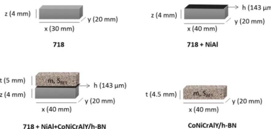
The 718 alloy was used as a substrate (c.a. 4 mm thick). lt was
ultrasonically cleaned in acetone and then grit blasted with alumina to enhance the adherence between the coating and the substrate. Nickel 5 wt.% Aluminum thermal spray powder (Metco 450NS, Oerlikon) was used as the feedstock powder for the fabrication of the NiAl coating. The NiAl sublayer accommodates the thermal expansion mismatch between the abradable coating and the substrate. It serves also as a rough undercoat helping attachment of the abradable coating. The CoNiCrAlY/h BN/polyester powder (Metco 2043, Oerlikon ; D90:
140μm, D50: 75 μm, D10: 35 μm), with a composition of 30Co 25Ni
16Cr 6Al 0.3Y, 4 h BN, 15 polyester and 3 organic solids (in wt.%), was selected as the feedstock powder for the preparation of the CoNiCrAlY/ h BN/polyester abradable coating. Both coatings were deposited by atmospheric plasma spraying (APS) on one side of the 718 substrate (Fig.1.). Finally, the whole system, i.e. 718+NiAl + CoNiCrAlY/h BN/ polyester was heat treated at 450 °C in order to burn away the polyester component and create porosity within the CoNiCrAlY/h BN coating and thus, to improve its abradability. The as prepared system was divided into smaller pieces of c.a. 20 mm x 40 mm by an electrical discharge machining procedure using CUT 20 P machine (GF AgieCharmilles) equipped with a Cu/Zn wire (Ø = 0.25 mm).
In addition to the complete system, i.e. 718+NiAl + CoNiCrAlY/h BN, three other sets of samples were prepared, a 718 alloy without any coating, a NiAl coated 718 (718+NiAl) and a CoNiCrAlY/h BN sample (Fig. 1). Those samples were prepared in order to perform necessary oxidation kinetics calculations and to complete characterizations. The 718+NiAl sample was fabricated following the same procedure as described above, but without deposition of the CoNiCrAlY/h BN coating and thus, without the post deposition heat treatment. The CoNiCrAlY/h BN sample was prepared by removing the abradable layer from the 718+NiAl + CoNiCrAlY/h BN system using a high perfor
mance tabletop cut off machine (Secotom 50, Struers). The system was
cut in two pieces c.a. 0.5 mm above the NiAl layer (to make sure that none of it remained on the CoNiCrAlY/h BN sample). The 718 plate was cut into smaller pieces of c.a. 20 mm x 30 mm using the same machine to produce samples.
All prepared samples were ground using a manual polishing ma chine (Miniatech 263, Presi) with SiC abrasive papers with grades going from P80 to P600. All sides of the samples were ground except for the NiAl or CoNiCrAlY/h BN coated surfaces. Afterwards, the samples were
cleaned with acetone andfinally rinsed with ethanol in an ultrasonic
bath for 5 min.
2.2. Estimation of the NiAl and CoNiCrAlY/h BN surface areas
Since, the CoNiCrAlY/h BN coating is very porous, its porosity
(Section 2.2.1) and specific surface area (Section 2.2.2) were de
termined first to calculate properly its surface area. For the NiAl
coating, in turn, its roughness must be considered (Section 2.2.3) to correctly estimate its surface area. Having these data, the surface areas of all studied systems were calculated (Section2.3.).
2.2.1. CoNiCrAlY/h BN abradable porosity measurements
Porosity and pore size distribution were measured by mercury in trusion porosimetry using the AutoPore IV analyzer (Micrometrics),
which allows detection of pores in the 0.003 600μm range. The mea
surements were performed up to 414 MPa. In order tofit the mea
surement cell, the CoNiCrAlY/h BN abradable coating was divided into smaller pieces of c.a. 5 × 5 × 5 mm3.
The total percentage porosity (Ptot) was calculated by:
=
Ptot 100dapp HgV (1)
where dappis the apparent density of the scaffold and VHgis the total
mercury intrusion volume per gram of analysed specimen. The pore size distribution was calculated using the differential mercury intrusion volume plotted versus the pore size.
2.2.2. Estimation of the CoNiCrAlY/h BN abradable surface area The critical step for the oxidation kinetics calculations was the es timation of the abradable surface. The CoNiCrAlY/h BN coating ex hibits high surface area, which had to be considered in order to estimate the real surface in interaction with the environment. Therefore, its specific surface area was measured using a physisorption analysis with
the Quantachrome Autosorb 1MP equipment. In order tofit the mea
surement cell, the abradable coating was divided into small pieces of c.a. 3 × 3 × 1 mm3. Krypton gas was preferred to nitrogen gas to refine
the measurement for values lower than 5 m2/g, like in the case of this
study. The obtained specific surface area (SBET) was calculated using the
multipoint BET model. SBETwas multiplied by the mass of the coating in
order to obtain its total surface area. The mass of the coating, in turn, was calculated using the Eq. 12 (Section2.3).
2.2.3. Estimation of the NiAl coating surface area
In order to correctly estimate the surface area of the NiAl coating, its roughness has to be considered. Therefore, its surface topography was investigated using a variation focus microscope (S neox, Sensofar, MAG
10X, 1μm vertical resolution) equipped with SensoMAP software. A 3D
surface numerical model that estimates the surface area by considering
its roughness was developed by Sanviemvongsak et al. [14]. This
method was used to approach the real surface area from roughness measurements and to take it into account for the analysis of oxidation kinetics. The model is built on the assumption that the surface presents periodic peaks and valleys, and thus can be represented as a 3D sinu soidal surface. This is a rough assumption that makes the modelling an approximation method to estimate surface area ratios. Two roughness
parameters from the ISO 4287 (1993) standard were used. Thefirst
corresponds to the mean height parameter Rc, which characterizes the amplitude average of a profile (→z), and corresponds to the average of all maximum peak to valley heights (Zti) of profile elements, Eq.2.
∑
= = Rc m Zt 1 i m i 1 (2)The second corresponds to the mean width parameter Rsm, which is the spatial or periodic parameter (→x y,→) which corresponds to the average width (XSi) of profile elements, Eq.3.
∑
= = Rsm m XS 1 i m i 1 (3)By controlling the amplitude (→z) and the periodicity of the signal/ profile following two directions (→x y,→), the developed area can be as
sociated with a sinusoidal“egg box” like model. From this model, its
surface ratio was numerically determined using Matlab® software.
2.3. Surface area calculations
The surface areas of the described above systems were calculated as follows: = + + S718 2xy 2xz 2yz (4) = ′ + ′′ + S718 NiAl S718 S NiAl (5) = ′ + ′ + ′ + + − −
S718 NiAl CoNiCrAlY h BN/ S718 SNiAl SCoNiCrAlY h BN/ (6)
=
− −
SCoNiCrAlY h BN/ SBETmCoNiCrAlY h BN/ (7)
With x y, andz the width, the length and the thickness of the 718 substrate respectively,SBET the specific surface area of the abradable
coating (estimated as described in Section2.2.2.),mCoNiCrAlY h BN/ − the
mass of the abradable coating alone, Si the surface of the following
systems: 718, 718+NiAl, 718+NiAl + CoNiCrAlY/h BN and CoN iCrAlY/h BN,S′iandS′′i the surface of 718, NiAl and CoNiCrAlY/h BN
materials when composing the various systems as described by Eqs.
8 11: = + + S'718 xy 2xz 2yz (8) = + S'NiAl 2xh 2yh (9) = ′ − − −
S'CoNiCrAlY h BN/ SBETmCoNiCrAlY h BN/ xy (10)
= + +
S''NiAl xy 2xh 2yh (11)
With h the thickness of the NiAl coating (estimated from the SEM
images, see Fig. S1, Supporting Information),σ the surface parameter
taking into account the roughness of the NiAl coating (estimated as described in Section2.2.3., equal to 1.21 in this study), ′SNiAl the NiAl
surface in the complete system and S′′NiAl the NiAl surface in the
718+NiAl system. The mass of the abradable coating in the 718+NiAl
+CoNiCrAlY/h BN system (m'CoNiCrAlY/h BN), in turn, was calculated
using the following equation:
′ − = + + − − ′ − ′
mCoNiCrAlY h BN/ m718 NiAl CoNiCrAlY h BN/ ρNiAlVNiAl ρ718V718
(12)
Where: m718+NiAl+CoNiCrAlY/h BN the total mass of the 718+NiAl +
CoNiCrAlY/h BN system,ρNiAl,ρ718 the density of the NiAl and 718
alloys respectively, and V’NiAl and V’718the volume of NiAl and 718
within the complete system respectively ( ′VNiAl=xyhandV′718=xyz).
2.4. Isothermal oxidation tests
The isothermal oxidation tests were carried out in a Carbolite CWF 1300 furnace under laboratory air for 500 h. The specimens were oxi dized at 750 and 900 °C, and then cooled to room temperature after 50, 100, 240 and 500 h, for weighing. The sensitivity of the balance (Sartorius ME215 P) was ± 0.02 mg. The oxidation behaviour was evaluated by plotting the mass variation per unit surface area as a function of the exposure time. Moreover, the parabolic oxidation rate constants (kp) were determined for time intervals between 50 and 500 h
and plotted on an Arrhenius diagram together with some reference data. These calculations were performed for individual alloy or coatings (i.e. 718 alloy, NiAl and CoNiCrAlY/h BN coatings). To do the latter,
the following equations were used: = ⎛ ⎝ ⎞ ⎠ k m S t Δ 1 p i i 2 i (13)
With Δmi the mass variation of the whole system (718+NiAl or
718+NiAl + CoNiCrAlY/h BN) or a material of the system (718 or NiAl
or CoNiCrAlY/h BN), Si the corresponding surface and t the oxidation
time. In the case of NiAl and CoNiCrAlY/h BN coatings, the corre sponding mass variation was estimated based on the kinetics of the
other materials composing the system, using Eqs.14 17respectively
and Eqs. 8 and 9 (for the 718 and NiAl surface determination):
∆mNiAl= ∆m718+NiAl− ∆m718 (14)
∆mNiAl= ∆m718+NiAl−S'718 kp718t (15)
And
∆mCoNiCrAlY h BN/ − = ∆m718+NiAl CoNiCrAlY h BN+ / − − ∆m718− ∆mNiAl (16)
∆ = ∆ − − − + + − m m S k t S k t ' '
CoNiCrAlY h BN NiAl CoNiCrAlY h BN p NiAl p
/ 718 / 718
NiAl
718
(17) With kp718andkpNiAlcalculated for the corresponding time interval.
2.5. SEM observations, EDS, XRD and Raman spectroscopy characterization
The coating phases and oxides were identified by XRD with a D8
Advance Series 2 (Bruker) using Cu Kα radiation (λ = 0.15406 nm).
The range of the scattering angles (2θ) was varied between 20° to 100°. Samples were continuously scanned with a step size of 0.03° (2θ) with
3 s per each step. XRD diffractograms were complemented by Raman
spectroscopy using a LabRAM HR 800 (Horiba) spectrometer equipped with a confocal microscope. The analysis was performed between 100
and 1800 cm−1and between 3700 and 4800 cm1, the latter interval
made it possible to follow thefluorescence signal of the Cr3+ions as an
impurity in the alumina, using a 532 nm laser. Observations of the re ference and oxidized specimens were performed using a LEO 435 VP or FEI Quanta450 SEM equipped with an IMIX (PGT) or Quantax (Bruker) EDS, respectively. Two SEM observation modes were used, back scattered electrons (BSE) and secondary electrons (SE).
3. Results and discussion
3.1. Characterization of as sprayed coatings
Fig. 2shows the XRD patterns of the feedstock CoNiCrAlY/h BN/ polyester powder and the as sprayed CoNiCrAlY/h BN abradable coating. The diffraction peaks of the powder were attributed to the γ, γ’ (γ Co Ni Cr matrix and γ’ Ni3Al) andβ NiAl phases. The β NiAl was not
Fig. 2. XRD pattern of the CoNiCrAlY/h-BN/polyester feedstock powder (black) and the as-sprayed CoNiCrAlY/h-BN abradable coating (grey).
detected in the coating. Previous studies on CoNiCrAlY bond coatings pointed out that theβ phase may dissolve into the γ matrix due to se vere plastic deformation of the particles upon impact with the substrate [15,16]. Some results indicate that theβ NiAl phase did not have en ough time to precipitate within theγ matrix in the rapid solidification
part of melted splats [17]. Some studies on CoNiCrAlY based thermal
barrier coating systems showed that theβ phase content increases upon increasing the content of unmelted particles. Since theβ phase contains a large reservoir of Al, the presence of unmelted particles within the
coating increases its oxidation resistance [18]. Note that some un
melted particles were found within the whole thickness (c.a. 5 mm) of the CoNiCrAlY/h BN abradable coating prepared in this work (see
below). However, their quantity and thus the proportion of theβ NiAl
phase was too small to be detected by XRD.
The XRD pattern of the feedstock powder exhibits peaks assigned to polyester. As expected, these peaks were not present in the XRD pattern of the CoNiCrAlY/h BN abradable coating due to the post spraying thermal treatment. The XRD pattern of the feedstock powder contains peaks that are attributed to the presence of h BN. These peaks are not observed in the diffractogram of the coating, but the h BN component
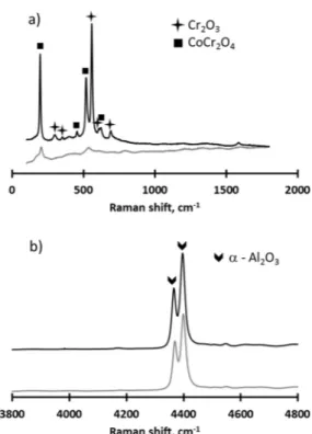
was detected by Raman spectroscopy (Fig. 3).
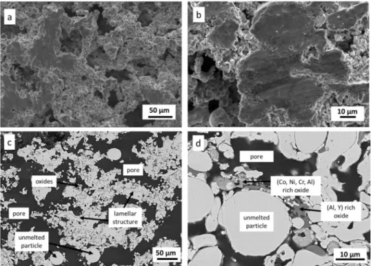
Fig. 4depicts the surface and cross sectional SEM observations of the as sprayed CoNiCrAlY/h BN abradable coating. It shows that this coating consisted of a lamellar structure, unmelted particles, pores and some oxides. It is a typical description of abradable coatings deposited by the thermal spray procedure [2]. The diameter of unmelted particles,
estimated from SEM images, varied from 1.4 to 27.5μm, whereas the
diameter of the CoNiCrAlY particles from the feedstock CoNiCrAlY/h
BN/polyester powder varied from 2.1 to 37.3μm. The distribution of
oxides was very heterogeneous and they were present across the entire thickness of the coating. EDS analysis shows that the dark grey areas correspond to Al and Y rich oxides. They can be easily distinguished from the mixed (Co,Ni,Cr,Al) rich oxides which exhibit a middle grey contrast. These oxides formed during the deposition process of the abradable coating. Their content seemed low as they were not present
in the XRD diffractograms. However, Raman bands assigned to the
CoCr2O4spinel and Cr2O3 were observed (Fig. 3). The formation of
similar oxides was also observed within an as sprayed CoNiCrAlY coating for thermal barrier coating systems [18].
The CoNiCrAlY/h BN coating exhibited a lamellar structure due to the deformation of melted particles upon contact with the substrate.
Fig. 3. Raman spectroscopy analyses of the as-sprayed CoNiCrAlY/h-BN abradable coating.
Fig. 4. Surface (a, b) and cross-sectional (c, d) SEM observations of the as-sprayed CoNiCrAlY/h-BN coating. (a) and (b) SE images, (c) and (d) BSE images. Fig. 5. Distribution of the pore diameter for the as-spayed CoNiCrAlY/h-BN abradable coating.
The formation of pores and the quantity of porosity are controlled through the amount of entrapped polyester in the coating [2]. To create the desired porosity, the coating requires a polymer removal by post deposition heat treatment. As a result, a web like metallic structure is
formed. This architecture allows excellent friability against titanium alloy, steel or superalloy blades. Coating porosity can vary from 35 to 60 vol.% [2]. In this study, the abradable coating exhibited a maximum porosity of 62 vol.% determined as explained above (Section2.2.1). The distribution of the pore diameter is shown inFig. 5. It is a tetramodal
distribution with the pore diameters of 6.1 nm, 0.84μm, 3.6 μm and
22.4μm. The biggest pores mainly contribute to the total volume of
porosity. This is consistent with the SEM pictures (Fig. 4. pores of several tens of microns) and characteristic of a macroporous material. The specific surface area of the abradable coating, equal to
0.6285 m2. g−1, is low for this kind of measurements but matches
perfectly the pore size description above. The obtained value was multiplied by the coating mass in order to obtain the total surface area of the CoNiCrAlY/h BN abradable coating. Its mean value of
61,744.75 cm2is enormous compared to the bulk material and comes
from the presence of macropores within the material.
Fig. S2. shows the XRD pattern of the as sprayed NiAl coating. The diffraction peaks can be attributed mainly to the γ phase. Fig. S1 depicts the surface and cross sectional SEM observations of this coating. The surface of the coating is quite rough and its roughness was accounted
Fig. 6. Mass variations versus time for (a) the 718+NiAl + CoNiCrAlY/h-BN sample, (b) the CoNiCrAlY/h-BN coating, (c) the 718 alloy and (d) the NiAl coating at 750 °C (grey symbols and line) and 900 °C (black symbols and line).
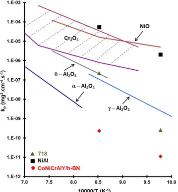
Fig. 7. Arrhenius diagram gathering kpdata obtained for the CoNiCrAlY/h-BN
and NiAl coatings as well as for the 718 alloy, and literature data for Al2O3
[19], NiO [20] and Cr2O3oxides [21]. The kpvalues were determined for time
interval between 50 h and 500 h.
Fig. 8. XRD patterns of CoNiCrAlY/h-BN abradable coating after oxidation in air at 750 °C (grey) and 900 °C (black) for 500 h.
for in the surface area calculations (as explained in Section2.2.3). Its
mean surface area of 9.23 cm2was 1.2 times larger than the smooth
material. The average thickness of the NiAl coating was 143μm and
consisted of lamellar structured, unmelted particles of a Ni rich matrix and Al rich oxides. These oxides formed during the coating deposition.
3.2. Oxidation kinetics
The mass variations of the 718+NiAl + CoNiCrAlY/h BN sample oxidized under laboratory air at 750 and 900 °C are shown inFig. 6a. At 900 °C, the sample exhibited three stages during the oxidation process. A transient growth stage occurred within thefirst hours, but since the first withdrawal of the sample was performed after 50 h, the corre sponding data points are not recorded. Afterwards, the oxidation rate
briefly decreased, followed by a high mass gain rate between 240 and
500 h. As seen inFig. 6b, the curves for the CoNiCrAlY/h BN coating
exhibit a similar behaviour. A similar trend was also described for a thermal barrier coating system based on a CoNiCrAlY/h BN coating
oxidized at 1100 °C [18]. Such behaviour was not observed for the
samples oxidized at 750 °C, indicating that the coating withstood well this temperature (Fig. 6a, b).
The 718 alloy and NiAl coating exhibited higher growth rates as compared to the CoNiCrAlY/h BN coating as seen inFig. 6b, 6c and 6d. The Arrhenius diagram (Fig. 7), from which the oxidation kinetics are determined using eq. 13, suggests that at 900 °C in air the 718 alloy
forms chromia, whereas the NiAl coating forms NiO the oxide with the
fastest oxide scale growth observed in this study. This was confirmed by XRD analysis (see Supporting Informations, Fig. S4). The CoNiCrAlY/h BN coating presented the lowest oxidation kinetics in this study with kp
values of 1.12 × 10⁻¹¹mg2. cm4.s1and 2.29 × 10¹⁰mg2. cm4.s1at
750 and 900 °C, respectively. The kpvalues were determined for time
interval between 50 and 500 h. To refine kinetics calculation, the
evolution of the abradable coating surface area due to oxidation could be taken into account. However, in this study, all calculations were done with the initial surface areas (i.e. before oxidation).
3.3. Characterization of coatings after oxidation
Fig. 8shows the XRD patterns of the CoNiCrAlY/h BN abradable
coatings after oxidation at 750 and 900 °C for 500 h. The γ and γ’
phases, Cr2O3, CoNiO2and CoCr2O4oxides were found on the coating
surface after oxidation. The quantity of oxides increased with in creasing temperature. Indeed, the corresponding XRD peak intensities were much higher at 900 °C than at 750 °C. The Raman spectroscopy
Fig. 9. (a) Raman spectroscopy and (b) fluorescence spectroscopy of the CoNiCrAlY/h-BN abradable coating after oxidation in air at 750 °C (grey) and 900 °C (black) for 500 h.
Fig. 10. SEM observations of the surface of CoNiCrAlY/h-BN abradable coatings after oxidation at 750 °C (a, b) and 900 °C (c, d) for 100 h (a, c) and 500 h (b, d). Observations realized using the SE detector.
results confirmed the presence of Cr2O3and CoCr2O4(Fig. 9a) while the
fluorescence spectroscopy analysis revealed the presence of α Al2O3
within the abradable coating (Fig.9b). A continuous scale of Al2O3acts
as a diffusion barrier to protect the coating from further oxidation,
thereby increasing the service life of the coating at elevated tempera tures [22 25]. However, due to alumina scale formation, the Al content within the coating decreases with time. Below a critical level of Al
within the coating, rapidly growing oxides such as NiO, Cr2O3 and
(Ni,Co)(Al,Cr)2O4start to nucleate [26,27], which can cause deviation
from a classical parabolic behaviour of the mass variations, as noted in this study (Fig.6a, b) and during previous investigations [18].
Fig. 10presents surface morphology of the abradable coating after oxidation at 750 and 900 °C for 100 and 500 h. The oxide grain size increased considerably with temperature and oxides exhibited poly hedral structures at 900 °C, mainly (Co,Ni) or (Co,Cr) rich oxides. At 750 °C, another interesting morphology can be observed, i.e. long nee dles. Some of them were also present after oxidation at 900 °C for 100 h, but none were observed after 500 h at this temperature. The presence of
well defined needles at 750 °C can be assigned to the formation of
metastableθ Al2O3during initial steps of oxidation that transforms ir
reversibly into α Al2O3 with time without changing its morphology
[19]. At 900 °C, the content of the needles decreased due to the ac celerated transformation fromθ Al2O3toα Al2O3at this temperature
[28].
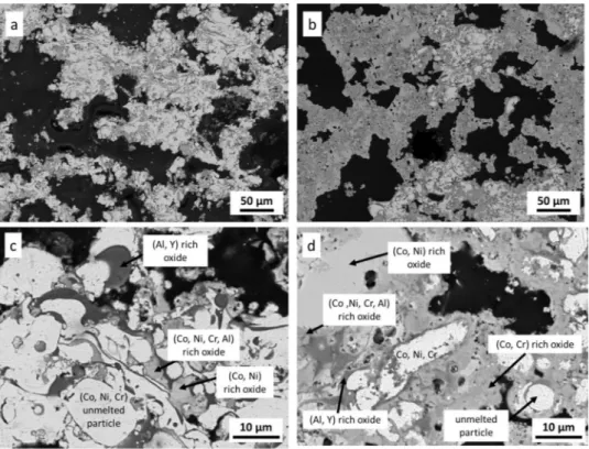
Fig. 11presents the cross sectional images of the CoNiCrAlY/h BN abradable coatings after oxidation at 750 and 900 °C for 500 h. As shown by EDS analysis, the (Al,Y) rich oxides exhibit a dark grey contrast while the (Co,Ni) , (Co,Cr) and (Co,Ni,Cr,Al) rich oxides ex hibit a medium grey contrast. As expected, the content of the oxides, especially the rapidly growing oxides, increased with increasing tem perature. The oxides were present in the whole volume of the coating. One can note that the (Al,Y) rich oxides appear mainly around un melted particles and lamellar structures. The interior of these structures remains metallic, but with a reduced quantity of Al. The latter diffused to the surface of the particles and lamellar structures and created a protective Al2O3 layer [18]. It suggests that the unmelted particles
exhibit a larger Al reservoir than the surrounding material. This ex plains the differences in the oxidation behaviour between different parts of the abradable coating and the heterogeneous oxide distribu tion. However, as explain previously, unmelted particles represent only a very small proportion of the coating. Such heterogeneous behaviour is therefore locally observed.
4. Conclusions
The high temperature oxidation resistance of a thermally sprayed CoNiCrAlY/h BN abradable coating was studied at 750 and 900 °C. The as sprayed coating exhibited a lamellar structure, unmelted particles, pores and some oxides (mainly (Al,Y) rich oxides and (Co,Ni,Cr,Al) rich oxides). The enormous surface area of the coating resulting from its high porosity was carefully characterised and then taken into account in the kinetics calculations. After 500 h at 900 °C in laboratory air, the mass variations exhibited deviation from a classical parabolic beha viour, indicating oxide growth acceleration mainly due to the formation of rapidly growing oxide. These oxides were distributed across the whole volume of the coating, except for some unmelted particles ob served locally across the coating thickness. The latter exhibited a large reservoir of Al which allowed the formation of a protective, thin and adherent alumina scale around the particles making them resistant to oxidation.
Data availability
The raw/processed data required to reproduce thesefindings cannot
be shared at this time due to the industrial character of our study. Acknowledgments
We would like to thank Safran Aircraft Engines (Site de Corbeil, Evry, France) for thefinancial support. We thank Alain Castillo from the GET OMP laboratory and David Neumeyer from the CEMES laboratory in Toulouse for the BET specific surface analysis. We acknowledge
Fig. 11. Cross-sectional SEM observations of CoNiCrAlY/h-BN abradable coatings after oxidation in air at 750 °C (a, c) and 900 °C (b, d) for 500 h. Observations realized using the BSE detector.
[1] W. Brandl, D. Toma, H.J. Grabke, The characteristics of alumina scales formed on HVOF-sprayed MCrAlY coatings, Surf. Coat. Technol. 108–109 (1998) 10–15, https://doi.org/10.1016/S0257-8972(98)00613-6.
[2] S. Wilson, Thermally sprayed abradable coating technology for sealing in gas tur-bines, The Future of Gas Turbine Technology, 6th International Conference (2012) Paper ID Number 51.
[3] P. Poza, P.S. Grant, Microstructure evolution of vacuum plasma sprayed CoNiCrAlY coatings after heat treatment and isothermal oxidation, Surf. Coat. Technol. 201 (2006) 2887–2896,https://doi.org/10.1016/j.surfcoat.2006.06.001.
[4] B.G. Mendis, B. Tryon, T.M. Pollock, K.J. Hemker, Microstructural observations of as-prepared and thermal cycled NiCoCrAlY bond coats, Surf. Coat. Technol. 201 (2006) 3918–3925,https://doi.org/10.1016/j.surfcoat.2006.07.249.
[5] M. Mohammadi, S. Javadpour, A. Kobayashi, S.A. Jenabali Jahromi, K. Shirvani, Thermal shock properties and microstructure investigation of LVPS and HVOF-CoNiCrAlYSi coatings on the IN738LC superalloy, Vacuum 88 (2013) 124–129, https://doi.org/10.1016/j.vacuum.2012.02.003.
[6] D. Sporer, S. Wilson, P. Fiala, R. Schuelein, Thermally sprayed abradable coatings in steam turbines : design integration and functionality testing, ASME Turbo Expo 2010: Power for Land, Sea, and Air Volume 7: Turbomachinery, Parts A, B, and C (2010) 2309–2317,https://doi.org/10.1115/GT2010-23568.
[7] N. Kostoglou, K. Polychronopoulou, C. Rebholz, Thermal and chemical stability of hexagonal boron nitride (h-BN) nanoplatelets, Vacuum 112 (2015) 42–45,https:// doi.org/10.1016/j.vacuum.2014.11.009.
[8] U. Bardi, C. Giolli, A. Scrivani, G. Rizzi, F. Borgioli, A. Fossati, K. Partes, T. Seefeld, D. Sporer, A. Refke, Development and Investigation on New Composite and Ceramic Coatings as Possible Abradable Seals, J. Therm. Spray Technol. 17 (2008) 805–811, https://doi.org/10.1007/s11666-008-9246-5.
[9] D. Aussavy, R. Bolot, F. Peyraut, G. Montavon, S. Selezneff, Thermomechanical Properties of CoNiCrAlY-BN-Polyester Composite Coatings Elaborated by Atmospheric Plasma Spraying, Key Eng. Mater. 606 (2014) 167–170,https://doi. org/10.4028/www.scientific.net/KEM.606.167.
[10] T.J. Nijdam, C. Kwakernaak, W.G. Sloof, The effects of alloy microstructure re-finement on the short-term thermal oxidation of NiCoCrAlY alloys, Metall. Mater. Trans. A 37 (2006) 683–693,https://doi.org/10.1007/s11661-006-0040-z. [11] G. Marginean, D. Utu, Cyclic oxidation behaviour of different treated CoNiCrAlY
coatings, Appl. Surf. Sci. 258 (2012) 8307–8311,https://doi.org/10.1016/j.apsusc. 2012.05.050.
[12] S. Nath, I. Manna, J.D. Majumdar, Kinetics and mechanism of isothermal oxidation of compositionally graded yttria stabilized zirconia (YSZ) based thermal barrier
coating, Corros. Sci. 88 (2014) 10–22,https://doi.org/10.1016/j.corsci.2014.06. 050.
[13] S. Salam, P.Y. Hou, Y.-D. Zhang, H.-F. Wang, C. Zhang, Z.-G. Yang, Compositional effects on the high-temperature oxidation lifetime of MCrAlY type coating alloys, Corros. Sci. 95 (2015) 143–151,https://doi.org/10.1016/j.corsci.2015.03.011. [14] T. Sanviemvongsak, D. Monceau, B. Macquaire, High temperature oxidation of IN
718 manufactured by Laser Beam Melting and Electron Beam Melting: effect of surface topography, Corros. Sci. 141 (2018) 127–145,https://doi.org/10.1016/j. corsci.2018.07.005.
[15] P. Richer, M. Yandouzi, L. Beauvais, B. Jodoin, Oxidation behaviour of CoNiCrAlY bond coats produced by plasma, HVOF and cold gas dynamic spraying, Surf. Coat. Technol. 204 (2010) 3962–3974,https://doi.org/10.1016/j.surfcoat.2010.03.043. [16] P. Richer, A. Zúñiga, M. Yandouzi, B. Jodoin, CoNiCrAlY microstructural changes
induced during Cold Gas Dynamic Spraying, Surf. Coat. Technol. 203 (2008) 364–371,https://doi.org/10.1016/j.surfcoat.2008.09.014.
[17] S. Saeidi, K. Voisey, D. Mccartney, The effect of heat treatment on the oxidation behavior of HVOF and VPS CoNiCrAlY coatings, J. Therm. Spray Technol. 18 (2009) 209–216,https://doi.org/10.1007/s11666-009-9311-8.
[18] J.J. Tang, Y. Bai, J.C. Zhang, K. Liu, X.Y. Liu, P. Zhang, Y. Wang, L. Zhang, G.Y. Liang, Y. Gao, J.F. Yang, Microstructural design and oxidation resistance of CoNiCrAlY alloy coatings in thermal barrier coating system, J. Alloys Compd. 688 (2016) 729–741,https://doi.org/10.1016/j.jallcom.2016.07.018.
[19] M.W. Brumm, H.J. Grabke, The oxidation behaviour of NiAl-I. Phase transforma-tions in the alumina scale during oxidation of NiAl and NiAl-Cr alloys, Corros. Sci. 33 (1992) 1677–1690,https://doi.org/10.1016/0010-938X(92)90002-K. [20] L. Berry, J. Paidassi, Contribution à l’étude de l’oxydation du nickel aux
températures élevées, Sci. Rev. Metall. 65 (1968) 651.
[21] H. Hindam, D.P. Whittle, Microstructure, adhesion and growth kinetics of protec-tive scales on metals and alloys, Oxid. Met. 18 (1982) 245–284,https://doi.org/10. 1007/BF00656571.
[22] Y. Bai, C. Ding, H. Li, Z. Han, B. Ding, T. Wang, L. Yu, Isothermal oxidation behavior of supersonic atmospheric plasma-sprayed thermal barrier coating system, J. Therm. Spray Technol. 22 (2013) 1201–1209, https://doi.org/10.1007/s11666-013-9979-7.
[23] W.R. Chen, X. Wu, B.R. Marple, P.C. Patnaik, The growth and influence of thermally grown oxide in a thermal barrier coating, Surf. Coat. Technol. 201 (2006) 1074–1079,https://doi.org/10.1016/j.surfcoat.2006.01.023.
[24] W.R. Chen, X. Wu, B.R. Marple, R.S. Lima, P.C. Patnaik, Pre-oxidation and TGO growth behaviour of an air-plasma-sprayed thermal barrier coating, Surf. Coat. Technol. 202 (2008) 3787–3796,https://doi.org/10.1016/j.surfcoat.2008.01.021. [25] W. Chen, X. Wu, P. Patnaik, B.R. Marple, D.R. Nagy, TGO growth behaviour in TBCs with APS and HVOF bond coats, Surf. Coat. Technol. 202 (2008),https://doi.org/ 10.1016/j.surfcoat.2007.09.042.
[26] M. Daroonparvar, M.A.M. Yajid, N.M. Yusof, M.S. Hussain, H.R.B.- Rad, Formation of a dense and continuous Al2O3 layer in nano thermal barrier coating systems for the suppression of spinel growth on the Al2O3 oxide scale during oxidation, J. Alloys Compd. 571 (2013) 205–220,https://doi.org/10.1016/j.jallcom.2013.03. 168.
[27] Y.J. Han, F.X. Ye, G.X. Lu, C. Liu, L.J. Hao, Residual stress evolution of thermally grown oxide in thermal barrier coatings deposited onto nickel-base superalloy and iron-base alloy with thermal exposure ageing, J. Alloys Compd. 584 (2014) 19–27, https://doi.org/10.1016/j.jallcom.2013.08.144.
[28] S. Kitaoka, T. Kuroyama, M. Matsumoto, R. Kitazawa, Y. Kagawa, Control of polymorphism in Al2O3 scale formed by oxidation of alumina-forming alloys, Corros. Sci. 52 (2010) 429–434,https://doi.org/10.1016/j.corsci.2009.09.031.
Gwenaelle Guittier from the SAP LGC laboratory in Toulouse for the macroporosity measurements. We thank our technicians and engineers Cedric Charvillat, Alexandre Freulon, Remi Garcia, Ronan Mainguy, Djar Oquab and Yannick Thebault for their precious help in setting up the experiments.
Appendix A. Supplementary data
Supplementary material related to this article can be found, in the online version, at doi:https://doi.org/10.1016/j.corsci.2019.02.030. References