OATAO is an open access repository that collects the work of Toulouse
researchers and makes it freely available over the web where possible
Any correspondence concerning this service should be sent
to the repository administrator:
[email protected]
This is an author’s version published in:
http://oatao.univ-toulouse.fr/20302
To cite this version:
Belaud, Jean-Pierre
and Negny, Stéphane
and Dupros, Fabrice
and Michéa, David and Vautrin, Benoît Collaborative simulation
and scientific big data analysis: Illustration for sustainability in
natural hazards management and chemical process engineering.
(2014) Computers in Industry, 65 (3). 521-535. ISSN 0166-3615
Official URL:
https://doi.org/10.1016/j.compind.2014.01.009
Collaborative simulation and scientific big data analysis:
Illustration for sustainability in natural hazards management
and chemical process engineering
Jean-Pierre Belaud a,b,*, Stéphane Negnya,b, Fabrice Dupros c,
David Michéa c, Benoît Vau trin d
a Université de Toulouse, INP-ENSIACET, 4, allée Emile Monso, F-31432 Toulouse Cedex 04, France b CNRS, LGC (Laboratoire de Génie Chimique), F-31432 Toulouse Cedex 04, France
c BRGM, 3 Avenue Claude Guillemin, 45060 Orléans, France ctoXALYA -OVH.COM Group, 6 bis, rue Riquet, 75019 Paris, France
AR T I C L E I N F O
Keywords:
ICI platform Computer-aided design 3D visualization
1. Introduction and scientific context
AB S TR A C T
Classical approaches for remote visualization and collaboration used in Computer-Aided Design and Engineering(CAD/E) applications are no longer appropriate due ta the increasing amount of data generated, especially using standard networks. We introduce a lightweight and computing platform for scientific simulation, collaboration in engineering, 3D visualization and big data management. This ICT based platform provides scientists an "easy-to-integrate" generic tool, thus enabling worldwide collaboration and remote processing for any kind of data. The service-oriented architecture is based on the cloud computing paradigm and relies on standard internet technologies ta be efficient on a large panel of networks and clients. In this paper, we discuss the need of innovations in (i) pre and post processing visualization services, (ii) 3D large scientific data set scalable compression and transmission methods, (iii) collaborative virtual environments, and (iv) collaboration in multi-domains ofCAD/E. We propose ouropen platform for collaborative simulation and scientific big data analysis. This platform is now available as an open project with ail core components licensed under LGPL V2.1. We provide two examples of usage of the platform in CAD/E for sustainability engineering from one academic application and one industrial case study. Firstly, we consider chemical process engineering showing the development of a domain specific service. With the rise of global warming issues and with growing importance granted ta sustainable development, chemical process engineering has tumed ta think more and more environmentally. Indeed, the chemical engineer has now taken into account not only the engineering and economic criteria of the process, but also its environmental and social performances. Secondly, an example of natural hazards management illustrates the efficiency of our approach for remote collaboration that involves big data exchange and analysis between distant locations. Finally we underline the platform benefits and we open our platform through next activities in innovation techniques and inventive design.
Sustainability is a paradigm for thinking about the future in which environmental, societal and economic considerations are
equitable in the pursuit of an improved lifestyle. Most of the economies are developing with breakneck velocities and are becoming epicenters of unsustainable global growth. Immense utilization of natural resources, waste generation and ecological
Abbreviations: API, Application Programming Interface; CAD, Computer-Aided Design; CAD/E, Computer-Aided Design/Engineering; CSV, Comma-Separated Values; GIS,
Geographical Information System; GUI, Graphical User Interface; GMT, Generic Mapping Tools; HTTP, HyperText Transfer Protocol; HTTPS, Hyper Text Transfer Protocol Secure; HPC, High Performance Computing; ICI, Information and Communication Technologies; IT, Information Technologies; LAN, Local Area Network; MS, Microsoft; Saas, Software As A Service; SME, Small Medium Enterprise; SOA, Services Oriented Architecture; SVG, Scalable Vector Graphies; TCP, Transmission Contrai Protocol; VTK, Visualization ToolKit; X3D, Extensible 3D; XML, eXtreme Markup Language; WAN, Wide Area Network; WYSIWIS, What You See Is What I See.
• Corresponding author at: Université de Toulouse, INP-ENSIACET, 4, allée Emile Monso, F-31432 Toulouse Cedex 04, France. Tel.: +33 05 34 32 36 48.
E-mail addresses: [email protected] Q.-P. Belaud), [email protected] (S. Negny), [email protected] (F. Dupros), [email protected] (D. Michéa),
[email protected] {B . Vautrin). https:/ /dx.doi.org/10.1016/j.compind.2014.01 .009
irresponsibility are the reasons for such a dire situation. With the world in majority debating over issues like climate change, water resources, food security, energy efficiency for the last few decades, it is evident that sustainability and green thinking have taken root in ail approaches and dialogs. Governments are rethinking their developmental paths adapted to ensure a sustainable lifestyle. Industry, academic institutions, public sectors are taking serious advancement to implement the same. A brief highlight of sustainability takes into consideration three pillars i.e. economic, social and environment. Engineering domains have to develop innovative solutions according to this new paradigm. One first industry to corne under scrutiny was the chemical processes and heavy industry sector; however this has tended to evolve to cover other sectors and different sizes of industry. Efforts in manufactur ing and chemical industries have been moving from "end of pipe" technological solutions to limit or control pollution, to the integration of the environmental preoccupation in early stage of product or process (preliminary) design at an industrial park level. Pollution control, eco-efficiency, life cycle thinking and industrial ecology are the main steps of sustainable manufacturing practices
[1].
At present scientific area of chemical process engineering and natural hazards management is recognized as a method to integrate an efficient sustainability analysis and strategy. Those two engineering domains provide handful solution to manage systems by enabling the use of modeling, simulation, optimiza tion, planning and control in order to develop a more sustainable product and process. In this context scientific simulation based on big data and collaborative work has to be developed for succeeding Computer-Aided Design/Engineering (CAD/E) of sustainable system.
In scientific simulation based High Performance Computing (HPC) area, pre and post-processing technologies are the keys to make the investments valuable. Besides, the data size and data mode! increase make it mandatory for industrial and academic users to have access to sufficient power on a remote and collaborative way. Our aim is to develop an open technological web platform that provides HPC, collaboration and 3D visualiza tion capabilities to end users and software developers for product design by simulation. A lot of research works, systems and toolkits have been proposed for distributed and remote scientific visualization of large data sets over scientific networks. A good overview of different solutions for distributed and collaborative visualization can be found in Brodlie et al. [2] and in Grimstead et al. [3]. Nevertheless, to our knowledge, a multi-domain collaborative platform for decision-making in simulation for complex systems, orchestrating transparently a set of advanced pre and post processing scientific visualization services is a real innovation. That is a fact that the collaborative part of the different existing systems is often reduced to basic tools such as "shared display". Current collaborative techniques have no advanced communication of visual objects and advanced person-machine interface dedicated to remote collaboration. As a consequence, the design of our platform will require innovations into: (i) pre and post processing semantic visualization services in distributed and parallel environments, (ii) 3D large scientific data set scalable compression and transmission methods, (iii) advanced collabo rative virtual environments for 3D data, and (iv) Computer-Aided Design/Engineering (CAD/E) usage for multi-domains of engi neering.
We discuss hereafter the three first items. Section 2 deals with last item for the needs for collaboration in CAD/E systems and illustrates some current industrial needs from BRGM experience. The Section 3 presents the platform without giving any deep technical information. This platform is now available as an open project with ail core components licensed under LGPL V2.1 and
advanced technical information can be found from the platform
documentation.1 Before drawing conclusion, the Section 4
provides two examples of usage of the platform in CAD/E for sustainability engineering from one academic application and one industrial case study.
1.1. Pre and post processing visualization services
The aim is to provide engineers and researchers with tools to operate on their meshes remotely. Mesh generation, optimization and adaptation are a topic highly studied in the literature [4]. The current solutions that actually enable such an analysis have two major drawbacks: they do not offer the possibility to distribute transparently the processing; they are mainly local solutions. The state of the art on scientific visualization environment has deeply evolved with the design of user-friendly solutions such as AVS, IBM/Data Explorer, Avizo, Covise, Ensight, VTK, Cassandra and many others. Recently, distributed and parallel visualization solutions such as the open source platform Paraview and the commercial package Ensight Gold/DR appeared. Nevertheless, there are still efforts to do for the deployment of these solutions on a large computing grid or HPC center.
1.2. Remote scientific 3D visualization
Due to the large volume of data handled, a lot of compression and progressive transmission methods have been proposed in the past to deliver in real time 3D content. These different methods can be classified into four main approaches:
• Image based streaming: the 3D data is stored on the server and only the 2D rendered images are streamed in real time to the server. It is the approach chosen by many solutions because it can be easily implemented and it ensures the best use of the network bandwidth.
• Object streaming: a 3D object is compressed and is progressively transmitted over the network. Specific file formats such as X3D and MPEG4-BIFS are generic formats for 3D object streaming. • Scene streaming: the data delivery is extended to the entire
scene. This approach is widely used for famous Massively Multiplayer Online Garnes such as Active Worlds or Second Life. • Scientific visualization streaming: the large volume of the scientific data, their time dependent deformation and the accuracy of mode! representation are important features that imply specific streaming methods.
In addition to this 3D visualization requirement, two optional needs for our platform are considered: (i) major 3D compression techniques; both mesh geometry and mesh connectivity compres sion techniques; to transmit 3D data over the internet and (ii) digital watermarking as a potential efficient solution for copyright protection. Those two capabilities are not developed in this article which is focused on the usage of the platform in engineering. 1.3. Collaborative environments and techniques
The DIS/HLA IEEE standard, on which most of military tactical simulations are based, illustrates how a distributed simulation manages a set of several entities which interact and communicate in "real time": when an action is executed, the related information or outputs are dispatched/broadcasted as "quickest" as possible in
the network. The more commonly used algorithms [5] deals with
the concept of "referentials" and "proxys", as we can find in
Simnet, NPSNet or OpenMASK platforms. The collaborative features are still limited:
• Only one remote shared display for ail the participants, • Very often only one cursor is visible to manipulate, navigate and
point out something on the screen,
• Users have to wait the authorization to navigate or to change the 3D content.
We aim to fill the gap between major available platforms and the new needs. Our project works on designing and demonstrating new mechanisms allowing several users to:
• Be aware of the presence of the other users, • Be aware of the actions of the other users, • Be aware of the bounds of other users' actions, • Better understanding of other users' activity,
• Join each other and collaborate thanks to ICI and common web usages,
• Share viewpoint between users.
2. CAD system and collaboration issues
2.1. CAD systems for multi-domains of engineering
Early efforts in computing tools for design were focused on solid modeling. Computing and computer system is now becoming a key position in any engineering field. The CAD system replies to the raw needs for an effective design process and a product delivery compliant with requirements. It relies on the evolution of computing materials, software technologies, architecture para digms and systems usages. The core pieces of CAD/E system are according to Zeng et al. [41]: (i) geometry, structure and process modeling, (ii) displays-based graphical visualization, (iii) numeric data-based behavioral analysis and simulation, (iv) network hosted remote collaboration, (v) data base-level functional integration, and (vi) product/process life cycle data management. Chandrasegaran et al. [6] discuss on the evolution and challenges of such system from "Pen-based digitizing" in 1963 to "collabora tive product development tools" in 2010 and list commercial packages of support tools for design in the industry. Recently the collaboration paradigm following the modern ICI has to be integrated within CAD/E system as argued by Goel et al. [7] who propose four characteristics for the next generation CAO systems: cognitive, collaborative, conceptual, and creative. The design is collaborative according to time, space, discipline and culture. Our frame is limited to time, space and discipline of collaboration.
The development of such computing systems is a practical solution for achieving remote collaboration. As a tool, they promote the creation and development of several types of teams, where ail members can communicate continuously on a flexible and constant basis. More especially, the collaboration paradigm, coupled with modern ICI, is a common means for expediting and improving engineering processes in CAO. Li et al. [8] examine the different methodologies and technologies of collaborative CAD systems. Collaborative product design in intra-organization and extra-organizations scope is now clearly recognized as an effective means for developing new products and improving competitive ness and creativity [9 ]. Such collaborative systems allow the design process to be developed by different, geographically separated teams. From a practical standpoint, modern ICI can reduce the carbon footprint of projects by cutting back on long-distance travel. But in addition to the remote collaborative engineering trend, they support the engineering process that invents innova tive solutions to deal with current sustainability engineering
issues. The new phase of the web (i.e. web 2.0) featuring new models, technologies and usages [ 10, 11] reveals that there is a potential to improve the quality of communication between the different engineers through a new generation of "CAD/E 2.0". 2.2. Collaboration issues
In current industrial practices, numerous activities or situations involve a multidisciplinary team of variable size. Due to the increasing complexity of product and processes, and to face the agility imperatives, new collaborative methods and tools must be created in order to facilitate exchanges between experts from different fields. Furthermore, it is not unusual that the team members can be dispatched to different part of the world. This diversity of thought, skills, backgrounds, gender is beneficial to appropriately solve the firms' problems but also to enable creativity. In addition to this internai diversity, firms have to include and manage externat knowledge and skills in their activities such as in open innovation [12]. The collaboration can be achieved at several time scales depending on its purpose: stealth in the case of an emergency situation, long term for a design project. Let us take two examples, in firms' activities to demonstrate the benefits of a collaborative platform.
Nowadays the design of product and/or process needs to staff an engineering organization with a diversity of disciplines and with various areas of expertise. For example in chemical related process engineering, we must create interdisciplinary team with various skills to solve design problems: physics, ultrasound, chemistry, materials, biochemistry, rheology and expertise within the chemical engineering (mixing, heat transfer, separation, drying, ... ). In this design phase, modeling and simulation play an important rote as they allow to study a broader range of options since they significantly reduce the risk of failure. In some firms in chemical engineering, 90% of the R&D is done in a virtual world with the remainder being physical validation [13]. As the process design progresses, the models become more detailed and increasingly complex. They include several thousands of equations often leading to systems with differential and algebraic equations to mode! the phenomenon that occur at the different temporal and spatial scales. The challenge consists in modeling various physical and chemical transformations coupled with fluids flows and heat and mass transfer. To build such models we need interdisciplinary skills: physics, chemistry, mathematics, informatics, ... The mode! is the result of a collaborative work that gives its quality. In addition to connect various experts across the world, a collabora tive platform allows to visualize rapidly the large amount of data produced by simulation, to enable learning at different physical scales, to achieve solutions with higher quality, to accelerate the design and to improve creativity. Like in chemical process engineering, numerous scientific domains have the same needs for a collaborative CAD/E platform for improving products and processes design thanks to modeling and simulation.
The second example deals with emergency situations: process supervision, natural hazards management, ... The specificities of such situations are that they are highly dynamic and constrained in time. In these situations, solving the problem requires decisions of stakeholders, more or less independently of each other's, but they must be pooled for efficiency reasons and synergy of means. To make a decision, an expert must consider a situation in its entirety, because the decision can be achieved by a situation that changes the environment and cause interactions. The development of such a collaborative environment involves significant locks; real time constraints, decisions in a limited time, a "light" decision-making system to accept multiple experts and that enables to visualize rapidly the consequences of some decisions and the evolution of a situation.
Collaborative platform for simulation-based design
10Mb/s 106
Worldwide networks
Fig. 1. A technological bottleneck.
2.3. Example of needs and usages from BRGM experience
Natural hazards events can have catastrophic impacts and trigger cascading effects (e.g., the Fukushima events). We are facing a shift from natural hazards protection to risk management. Assessing and managing multi-hazard and multi-risk phenomena require the combination and coordination of many capabilities and instrumental techniques, and involve expertise in various fields such as geophysics, social sciences, data analysis, and telecom munications. lt needs also a strong experience in crisis manage ment. The raie of ICT and CAD/E systems is to provide tools designed for sharing of data and risk information, best practices, and approaches in order to capitalize on knowledge and to feed decision-making process.
Severa! key features need to be considered in the design of a collaborative environment dedicated to Earth sciences. The importance of large three-dimensional data could be easily explained from the solid Earth domain. The large scale is not only coming from the spatial dimensions but also from the various properties/uncertainties that must be taken into account. This is also coming from the time domain. The ease of integration of new data formats is another requirement as Earth modeling gathers several research communities (geophysics, climate, geology, ... ). Based on a smooth access of the data, standard manipulations in a 3D volume (picking, clipping) have to be available as the interactions between scientists are mainly based on the explora tion of static or dynamic data.
Exploiting standard risk management approaches, collabora tive session with local stakeholders is of great importance. This leads to multiple flavors of the interface and several collaborative modes. In view of the dual raie of BRGM,2 the opportunity to strengthen remote collaboration between distant teams is also of key importance. BRGM is organized around its scientific center located at Orleans, France. This center brings together some one thousand experts in a wide range of natural hazard specializations in each administrative region in continental France and overseas (the French West Indies, Reunion Island, Mayotte). The regional team's size is limited, around 15 scientists who have developed a deep understanding of the local context. The computational facilities, with a cluster of more than 300 cores and 24 Terabytes of attached disk, are located in Orleans.
3. Collaborative simulation and 3D visualization platform
3.1. Main features and requirements
Our initiative is applied to scientific simulation and 3D visualization in hopes of breaking though some of the technologi cal bottlenecks confronting scientists by making possible collabo ration and remote processing of their data anytime and anywhere in the world with just a standard internet connection. With the collaboration of academics and industrial players, we are contending with a number of main challenges. The key objective
2 The French geological survey must provide support to public policy but also must maintain international industrial and commercial activities.
is to provide to academics and engineers from any simulation domain with an "easy-to-integrate" platform. Its characteristics should be open-process, web-based technologies, remote and reliable architecture, HPC capability, 3D visualization, collabora tive facility, common bandwidth, thin client-access (browser) and rich client-access (any modeling environment). It provides applications tailored to the approaches of very different commu nities such as geophysics, fluid dynamics, structure, biology, chemistry, and drug design. It considers mainstream technologies for service access (low bandwidth internet access, standard hardware for visualization, ... ). Its assets are in interactive and participative collaboration and not only remote "shared display" visualization. Moreover, these technologies must be easily accessible, and we provide the proper tools to manage ail the services from a user and administrator point of view, to gain full transparent access to these scalable resources: visualization clusters, grid computing, etc.
ln our scientific and industrial context, ICT helps facilitate and improve collaboration. The related technologies are computing platform, public/private cloud services, middleware, internet protocols and remote access via fixed or portable communication device. Our research activities aim at developing an innovative multi-domain collaborative platform for simulation-based design applications. Web-based technologies, based on shared High Performance Computing and visualization centers, enable researchers and engineers to manage very large data sets, including 3D data models, by using a single workstation anywhere in the world. A mere "standard" internet connection should be needed. Classical approaches to remote collaborative platforms for simulation-based design applications no longer afford a solution. One conclusion is that current approaches cannot efficiently support applications that generate huge amount of data (Fig. 1 ). This situation is critical for solid earth modeling as simulation and computation have corne to play a central raie. As an example, the EarthCube project,3 a community-driven data and knowledge environment for the geosciences, is providing seismologists with new data of tsunami. Modeling and imaging with this data requires powerful numerical modeling tools, automation of routine analysis tasks, and dedicated high-performance computing facilities due to the large temporal and spatial variability. Worldwide networks are still not powerful enough, especially with 10 Mb/s or Jess for an average daily user network, to retrieve data from centralized super-computer centers (from which data are transmitted to local clients for processing). Furthermore, researchers' and engineers' local computing resources are no longer suitable for processing such volumes of data. The real solution then is to deliver an ICT based platform for collaborative scientific simulations and 3D visualizations that relies on cloud computing architectures.
The platform aims to provide a versatile open platform for collaboration over large projects using three dimensional data. The previous part outlines the main issues faced today with virtual collaborative environments and one of the key-points is definitely the Jack of tools dedicated to the scientific community. The building of this platform has several objectives in mind:
Client Decompression
1
1
CollaborationIO
Dispatcher 1 Data Service Decompression Registry Service Manager Client11
CollaborationProject Manager
domain specific Service
Fig. 2. General architecture of the platform.
• Break the technical constraints and manage massive data and 3D visualization; working with large datasets, and more specifically on 3D representations, is network bandwidth consuming. The networking requirements for 3D collaboration have to be lowered using adapted and high-leveled compression methods and filtering techniques. Following the same idea, tools have to communicate through corporate firewalls. Therefore, one of the main key-points of this proposai is to allow the use of communications over HTTP/HTTPS. The need of network bandwidth is from 20 to 50 Mb/s allowing an interactive visualization of 20 frames per second (fps) at a resolution of 1280 x 1024 pixels. The use becomes inefficient and disappoint ing when the bandwidth falls to Jess than 10 Mb/s: the visualization is not interactive anymore with only 3-5 fps or Jess and lower the quality of the images introduces troubles and perception issues.
• Offer a generic platform for specific use cases; there is no single use case. Different domains in CAD/E with different needs will assure that the results of our project are not limited to one specific use. The idea behind this is to share as much as possible to provide while staying focused on the real expectations of the users. While the core of the system is conceived in a generic way, several industrial demonstrators are available to illustrate the versatility of the concept, with at stake, the ability for real user to appropriate the platform. As a proof of concepts, two main demonstrations from two different engineering domains are presented in Section 5.
• Share HPC resources and results to a larger audience; the deployment of the platform on clusters "on demand" can offer to Small and Medium Enterprises (SME) a first access to HPC resources. Moreover SME can share their simulations results with their contractors within the same environment. In the same line of sight, the project aims to provide access to high performance tools without costly investments in new computing hardware.
• Provide a collaborative virtual environment for distant partners; the platform provides tools for project teams of different partners, inside the same company or with subcontractors. Working remotely on the same project asks for a complete virtual platform both to work on the same data, and to share the results of the simulations. Furthermore, it must integrate with the existing tools.
Respecting these guidelines we ask for truly new tools adapted to the scientific community. Section 5 presents two CAD/E applications from different domains that take benefit from those capabilities. The parts below provide an overview of this platform.
3.2. Architecture overview
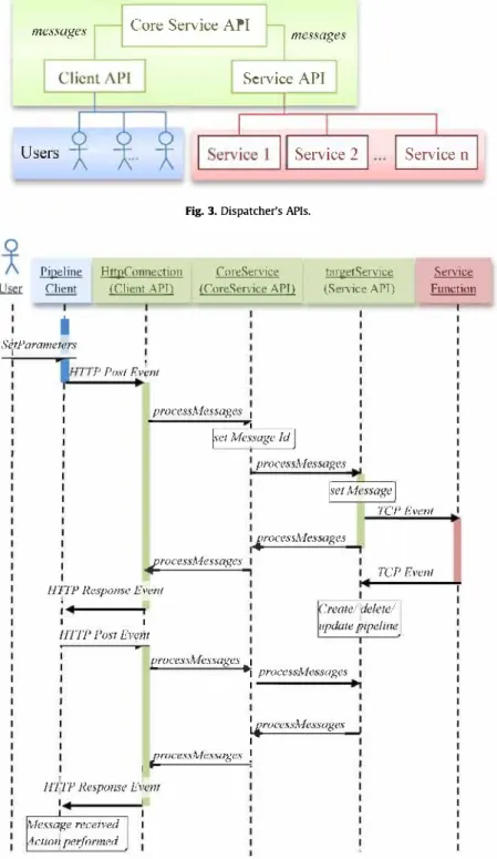
With high expectations from different domains, the architec ture must be capable of solving different problems. Our work aims not only at providing users with a complete solution via a simple internet connection, but also at allowing developers to easily provide new functionalities and customizations. To achieve this, the platform needs to be highly modular. Based on the outputs of earlier undertakings dealing with remote collaboration and remote scientific visualization, as demonstrated by Duval et al. [14], the proposed architecture is designed following SOA (Services Oriented Architecture) concepts, with clients connecting to a system providing services distributed on different servers (Fig. 2). Middleware is the core component, as well as collaboration oriented computing architecture, ensuring the consistency of the information across the whole system. It consists of four main parts: • Dispatcher, the communication sub-system, acting as an event loop and allowing clients, services and core components to exchange commands and notifications,
• Registry, the service description database, keeping trad< of ail functionalities provided by plugged-in services,
• Session, the session management component that handles client connections and the processing pipeline,
• Data proxy, the data exchange sub-system, which compresses and adapts data (including 3D data) to client and network capabilities.
The dispatcher component also provides the communication modules for clients and services to connect to the platform. To ease customization, ail the Application Programming Interfaces (API) of the different components have been specified prior to implemen tation, to be able to replace one implementation with another if the one provided by default does not suit user's needs. For example, the project provides communication layers for TCP, HTTP and HTTPS protocols between the clients and the middleware, but an additional one can be added as needed.
Services are the processing modules of the system. A service connecting to the middleware must describe the different functionalities it offers to users. Severa! "core" services are implemented, such as a Data Service exporting files from a shared file system, a Collaboration Service allowing people to interact on the same processing pipeline with different clients but also real processing services. For example, two different 3D data post processing engines have been implemented, displaying the features of Kitware' Paraview and CEi' Ensight, two of the tools most commonly used for scientific visualization.
me:.:mges Users Pipeline Client
i
Si'ParameiersCore Service API
HttpConnec.tion (Client A l'T)
messages
Service API
Service 2 Fig. 3. Dispatcher's APis.
CoreServic.e
(CoreSen·ice API) (Senice APT) targetService
·P Pos/ h•çnt processAJessages 1
__
,
__
J,·et Mdsuge Id-- --
j
processMessages fye/ MessageJ
Service n Service Function TCP Even/ /rocessA,Jessages H"J1P Response Even/ 1 1 llfT[' Post Ew1itf
rocess}vlessages TC!' Even/ .'reme/ de/etc/ update pipeline proces,ç./lA"essaxes 1•1 process.A1essages 1 1 : iruc-es.si\tfessages 1 froce.�·slv/essage.�· 1 11111P Respom·e Hvem ,'vfessage receinid ,Jc111m p,'ifnrnwd
Fig. 4. A sample scenario.
On the back office of the open cloud platform, due to the highly modular architecture the current solution offers several key features making it a real solution for "a sustainable adaptation" as defined by Elliot [15]: (i) elasticity of resources, with the possibility to support several identical services and load balance between them, it the available computing power can be adapted to the actual demand, using cloud resources for example; (ii) maintainability, adapting the platform to a new environment can be as simple as writing a new module to support a different communication protocol, for example; (iii) evolutivity, adding new capabilities can be achieved by writing new services without changing the core of the system; and (iv) collaboration, the platform offers a way to share costly resources and publish new research results. To validate these points, the platform was
developed from the start with users, not only to review it but also confront it with current and industrial use cases.
3.3. Service-oriented architecture
The services relation is supported by the dispatcher. Basically, the dispatcher is composed of three AP!s (Fig. 3). The core service API is an internai API used by the middleware to manage connections and user rights, sessions, etc. The client API allows client connection to the platform using TCP and HTTP as a failover. A service API allows service-plugging. The core service API communicates with the two others by sending and receiving messages. The sequence diagram, depicted in Fig. 4 illustrates a typical use of these AP!s. In this example, user sets parameters in
(1) lJ 08:L4] �tattcd ! l J 08: l 7] Usa l C!l3llCCt:i � FFF I Q"ftN< /, EEt-1 ($;cric ;
-: -·• [[�l-:i:'pomt :if\1e�i �- [[M (2)Pruph'pftu�&.tt: fi�: IE�lt-8e��-fl-J1S1;1-2501)..'(!r, tJ
1r.b:lrOl1',:;l•tLh;q.;m
(3)
(5)
Fig. 5. Client interface.
order to have an action performed by a target service and make it visible on its client. As services are accessed remotely, they can be distributed on different servers and, if needed, be deployed on a high-performance computing cluster. With this Software As A Service (Saas) approach, even if the client application runs on a simple laptop or any mobile device, users can benefit from ail the computing performance of the infrastructure on which the collaboration platform has been installed.
3.4. Generic client
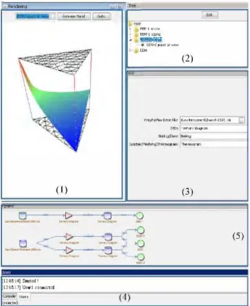
A generic client is also designed with 2D and 3D visualization capabilities. The middleware sends each client a complete description of ail the processes implemented by the registered services and its rights to use them. So this generic client provides a Graphical User Interface ( GUI) to the processing pipeline and off ers ail the possibilities of the platform. Fig. 5 provides a detailed representation of the client interface.
The Rendering view (Fig. 5-1) gives a graphie representation of a set of data. The platform provides three viewers by default. For "lD-view" models, like tables or data sets, the platform provides a CSV viewer. The main advantage of using the CSV viewer is the possibility to freely consult tables from the platform's client with no installation requirements. That is particularly useful for mobile devices like tablets and smartphones. 2D models are depicted using the SVG format. 3D models are represented according to an X3D viewer [16]. X3D is an open standard file format able to represent and communicate 3D scenes and objects using XML. Each viewer is implemented on the platform. Messages between services and a targeted viewer are ensured by the Dispatcher. The Tree view (Fig. 5-2) gives a hierarchical view of 3D elements scenes. Each scene can be composed from several points of view ( e.g. a particular view of the 3D element). The Edit window
(Fig. 5-3) sets needed parameters for targeted services to be
element element element
Fig. 6. Pipeline nomenclature.
computed. The Users window (Fig. 5-4) displays users connected for the active session. Data processing is represented through a Pipeline view (Fig. 5-5).
• Based on the nomenclature of Fig. 6, we can distinguish three kinds of elements in the Pipeline frame:
• Data Element represents an imported file (like .zip, .txt, .xis file, ... ) or generated data (like .x3d, .svg, .csv file, ... );
• Process Element indicates an action performed on a data element and that generates a new data element;
• View Element uses an appropriate viewer provided by the platform to visualize a data element. For a 3D mode!, it is called a Point of View.
Other clients can be developed, and existing visualization software can also be adapted to the platform to take advantage of it.
3.5. Users collaboration
To provide a workable collaborative platform, to synchronize several clients among each other and to ensure proper synchroni zation between clients and graphie performance are serious challenges as discussed in Sections 1 and 2 from a technical and usage perspective. A necessary formalization has been performed to allow several users to cooperate through distributed 2D and 3D GUI. It yields a globally strong synchronization (such as WYSIWIS) which guarantees consistency among the different points of views of a shared scene. It also results in a dedicated communication protocol based on HTTP/TCP. Thus co-operation between 2D and 3D interactions are possible. Master-Slave and Master-Master scenarios can be evaluated through actual case studies based on specific domain services. In addition to the five current frames of client, we plan to experiment the integration of common collaboration services 2.0 (i.e. instant messaging, experts' forum, and social networks). One subsequent issue is to initiate and develop a scientific community centered on collaborative simula tion and remote visualization thanks to the platform.
4. Result and illustration of usage
4.1. Delivery of the platfonn
The open cloud platform for collaborative scientific simulation and 3D visualization which is described in the previous section is now available for academic and industrial partners. Through a common versioning system, the platform can be deployed as cloud services on internet from any 1T and HPC provider (such as Oxalya OVH) or on intranet from inner 1T department. The platform is accessible as an open project on a forge web site.4 As such, while
being a true open-source project, the platform can also be linked to other commercial or proprietary products.
Software adaptation and domain-specific functionalities have to be developed in general by end-users in line with their specific needs. Severa! applications are already developed and deployed on
O.D Cl.99'2320.
-
·-klrUat �- � 0.111--
.
-
..
-
.
---Emllfl� �1nt 10.1> ---Eldll9- pr:a: ,t---�
0...11' �� !. Od> \'.11'\Jllllll. pnu..., <b:1lUL l'iil•m1.. 1111) J •• I:]�
.
Fig. 7. A client screenshot.
Fig. 8. Another client screenshot.
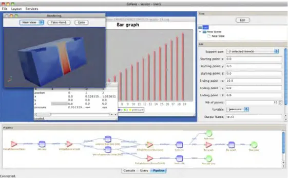
a few end-user LAN or WAN. Their development demonstrates the advantages provided by the cloud platform with a truly multi domain approach, intersecting interests of industrial and academic communities. Figs. 7 and 8 give screenshots of client side. Although most of the services of the platform are generic, major differences do remain in the specific areas of:
• Field of research: geophysics, structure, drug design, process engineering, ... ;
• Specific formats of data used by the communities involved: HDFS, MED, Ensight, ... ;
• Ergonomies related to specific needs and habits of each research community.
Tests of usability (functionalities & GUI), ease of access, performance and proposed feature improvements are carried
out as a common validation phase. The use of domain-specific applications with different needs ensures that the results are not limited to one specific use. While the core of the system is conceived generically, several present applications illustrate the versatility of the concept with, at stake, the ability for real users to appropriate the platform.
To demonstrate the approach and the benefits from the open cloud platform, we describe the scientific context and the scope statement of two different CAD/E usages: one academic applica tion targeting the chemical engineering domain and one industrial application dedicated to natural hazards management. The first application validates the platform by using it as a research support for sustainable process design in chemical engineering. That involves the development of a domain specific service to integrate into the platform architecture, the definition of a data handling process from a commercial application, and the choice of Windows
on server and client side. The second application completes this demonstration with an illustration of usage from BRGM in the management and monitoring of surface resources and risks. That assesses the large scale and big volume of data, the HPC capabilities of the platform, the deployment on Linux systems, and the remote collaboration and visualization from different geographic locations over the world.
4.2. Application to chemical process engineering 4.2.1. Scientific context
The chemical-related industry, which devotes its efforts to converting raw materials into a very wide range of products, is particularly concerned by sustainability [17]. Indeed, this industry plays a major role in the ecological impact of chemical product wastes and the consumption of non-renewable natural resources. The REACH regulation,5 the VOC directives6 and recent "roadmaps" from Anastas and Zimmerman [18] and IChemE7 go in this
direction by imposing strict constraints and new guidelines on chemical systems. These constraints are forcing chemical compa nies to give up some of their products or molecules. Diwekar and Shastri [19] review this "design for environment," and Ruiz Mercado et al. [20] propose a classification and definition of sustainability indicators for the evaluation and design of sustain able processes. We need to find substitution products or re-design separation operations respecting environmental constraints. Sustainability requires engineering at different scales, i.e. molecu lar, product, process, and system levels. At the product and process levels, to manage modeling of physical phenomena, simulation and visualization is a key milestone for engineers and scientists so as to succeed in meeting this challenge to devise sustainable chemical processes. Specific 2D/3D diagrams can help handle bio-physical chemical unit operations such as liquid-liquid extraction, absorp tion, distillation, reactive distillation, ... The aim of this service is to carry out necessary numerical calculations based on domain specific data in order to prepare equilibrium-phase diagrams like liquid-liquid equilibrium or liquid-liquid-vapour equilibrium. A phase diagram indicates a two or three-dimension graphical representation representing a system's physical states ( of a pure product or a mixture) with respect to variables such as composition, pressure and temperature. Typically, common MS Excel based 2D-visualization is used to construct these diagrams. However, these tools are inappropriate for dealing with the simultaneous representation of three components and additional parameters such as temperature or pressure. Although few tools do exist for generating 3D ternary models [21 ], none of them allow remote web access, HPC and collaborative engineering. By using a cloud platform for collaboration and visualization, we expect to facilitate the understanding and use of such scientific simulations. The service specific to the chemical engineering domain is developed and integrated into the platform architecture as illustrated by Fig. 2.
4.2.2. General design
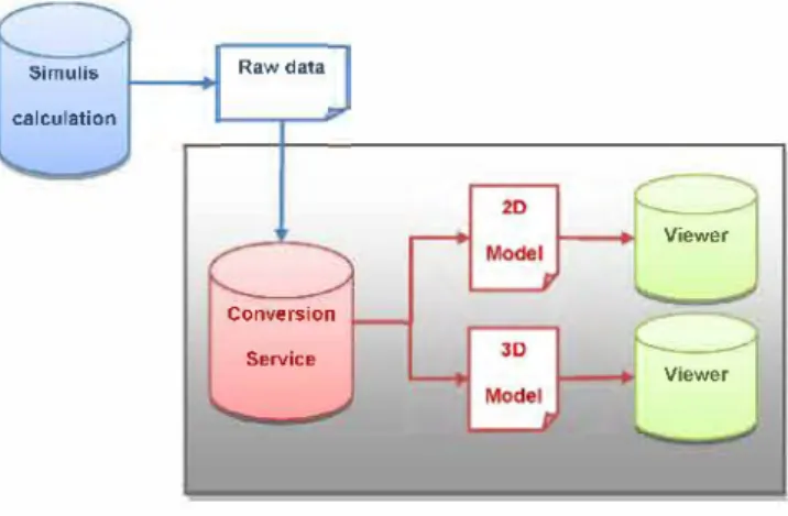
The main challenge is to create and deploy the chemical engineering domain specific service on the targeted collaborative platform, taking advantage of the infrastructure described in Section 3. Only a domain-specific application needs to be developed taking advantage of the platform core services, particularly the graphie generation of binary and ternary phase diagrams. Our raw data are obtained from a stand-alone Windows
5 http://ec.europa.eu/enterprise/sectors/chemicals/reach/index_en.htm.
6 The VOC Solvents Emissions Directive (Directive 1999/13/EC) amended through article 13 of the Paints Directive (Directive 2004/42/EC).
7 Institution of Chemical Engineers, http://www.icheme.org/.
Simulis calculation
Raw data
Conversion Service
Fig. 9. Model generation.
Viewel'
Viewer
software: Simulis from ProSim company, an application for thermodynamic properties calculations and phase equilibrium calculations. Severa! thermodynamic models are available, in particular models commonly used in the chemical industry. Thermodynamic property calculations ( density, enthalpy, entropy, ... ) and phase equilibria of mixtures can be performed for a system defined by its temperature, pressure and its composition. The Simulis tool can display binary diagrams or the cutting plane of ternary diagrams, but it cannot represent a 3D ternary diagram nor a thermogram. Based on Simulis raw data, the service is able to generate a 3D scatter plot, a meshing or a thermogram of a ternary diagram. The generation process is explained in Fig. 9.
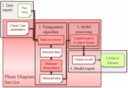
To achieve this, the service carries out a Delaunay triangulation following four major steps (Fig. 10):
• Data import: Simulis data and user/client parameters define the input data. A set of parameters is available to correctly describe the system;
• Triangulation algorithm: there are two main activities, data conversion and Delaunay triangulation [22 ]. Its properties are defined by [23,24]. We select the "Divide and Conquer'' algorithm proposed by [25] to compute this triangulation; • Mode! processing: the points are used to generate the output
mode!;
• Mode! export: this last step makes the output mode! visible on the client side.
4.2.3. Main usage
In chemical engineering, the need for 3D-visualization tool development arises from the following statement. After observing the diversity and complexity of binary systems, engineers generally feel uncomfortable with the greater diversity and complexity ternary systems can display. Chemical engineers calculate thermodynamic and physical properties and visualize 2D diagrams with MS Excel. However, the simultaneous represen tation of three-component compositions and other parameters such as temperature or pressure cannot be appropriately achieved with these tools. The platform is deployed via a private cloud. By using a 3D-visualization specific tool and related physical concepts, we expect to facilitate the understanding and use of these diagrams (Fig. 11 ). The study of such a ternary mixture is essential in order to design cleaner separation in chemical-related industries. Current goals are the calculation and visualization of binary and ternary phase diagrams and the determination of heteroazeotropic and azeotropic points. The process starts by studying each binary using the Simulis tool. We then study the ternary system following the four steps from Fig. 1 O. We simula te the ternary phase at a given pressure and export raw data in CSV
1. Data imp011
Phase Diagram
Service
2. Triangulation
algoritbm processineJ. Modcl
Output mode!
4 Mode! export
Collaviz Viewer
Fig. 10. Different steps of the service.
As:iei:t �ol�. 1;333 ---0 :}-�-��
...
~---
-�
_
Q_
�•�=l
-C:tid,!!ll5i!"!<�ne SL.��, ·---Fig. 11. A 3D visualization of a ternary mixture.
format on the platform. Delaunay triangulation service is executed. We obtain the necessary information to produce a meshing and a triangulation representation of the ternary diagram. Finally, an X3D transformation is performed. The X3D mode! obtained can be run using the platform client through a graphie user interface. We can interact with the 3D view, rotate, zoom, or focus on specific points, particularly the azeotropic points.
This application is slated for implementation in the framework of several scientific studies. For example, Rodriguez et al. [26] request for such a collaborative simulation and visualization service in order to work on heterogeneous batch azeotropic distillation by using heterogeneous entrainers to separate binary azeotropic mixtures by extractive distillation. The assessment of chemical component separation requires isovolatility curves and the volatility order diagram. A case is handled via rigorous simulation for separating the acetonitrile-water mixture with hexylamine or butyl acetate. Such work proposes a method for improving the distillation operation currently used by chemical related industries, and which respects environmental criteria.
4.2.4. Discussion
Chemical engineering has a need to compute a simulation of thermodynamic and physical properties and a 2D/3D ternary system visualization such as curves and diagrams for sustainable product design. At present, there is no accepted general methodology to guide sustainability. Although we can consider many proposais for integrating sustainability considerations into chemical process design [27,28,29] and agro-food process design [30]the area is stilljust emerging. But it is well accepted now that the scientific simulation of process life cycling, in "cradle to gate" or "cradle to grave" mode, is a key element in decision making for sustainability. We do believe that collaborative scientific simula tion and visualization compliant with ICT and 2.0 patterns can be a success factor in any computer-aided "ecodesign" process.
As a proof of concept related to the chemical engineering field, we deployed the platform on Windows server and client and adapted the platform to our specific activities. By taking advantage of this open platform, we developed a domain-specific service respecting the SOA architecture. This work allows a
2500000 1000000 !50000D M20000 09400CO œc.oooo 72Jl00l 70000,
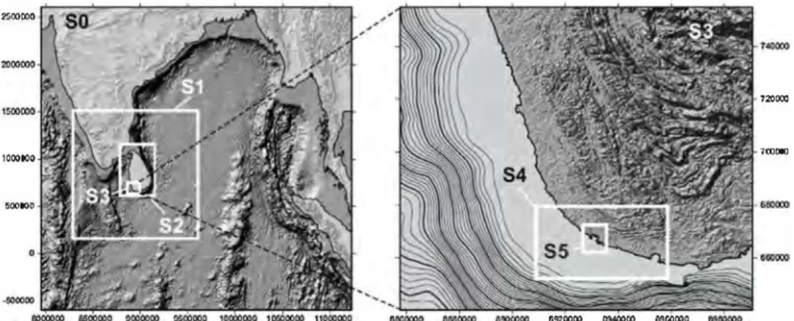
Fig. 12. The locations of the six nested grids used in our simulation.
3D representation to be made in collaborative web mode for research studies, e-leaming and lifelong leaming. Subsequent steps in our work will be to improve our service by adding advanced usage functionalities, taking more advantage from HPC for advanced chemical engineering simulation and optimization, and opening up new opportunities for distributed work in students' teamwork projects and research activities.
4.3. Application to natural hazards management 4.3.1. Scientific context
Efficient risk management requires prevention, emergency management and recovery tools that enable users to assess risk before the crisis, to optimize response capabilities during the emergency and to help promote recovery in the wake of a disaster. This standard description relies on the sustainable usage of the resources (material, human) available at these stages. Among the approaches available for risk management reviewed by Klügel
[ 31 ], scenario-based earthquake risk assessment constitutes a
powerful tool for estimating probable losses from future seismic events and the trade-off with respect to potential investments in infrastructure risk reduction ( considering, for instance, a single earthquake with given ground-motion characteristics).
In our case, the platform is deployed on Linux systems as a private cloud on BRGM's network. This solution provides security in the remote access to the computing resources. Moreover, we reuse existing 1T facilities with this smooth integration that maximize the sustainability of our tool. To evaluate the platform, we involve two regional centers in the French West Indies. These regions are prone to earthquakes and tsunamis, and the distance (more than 8 h of flight) requires adopting an efficient strategy of collaboration between distant scientists. Another important aspect is replacing standard visualization software by a customized view provided by the platform. In the case of tsunami modeling, one needs to consider two-dimensional data mainly post-processed with the Surfer commercial software package (Rockwave). For large-scale three-dimensional seismic data, Paraview (Kitware) is usually preferred.
4.3.2. Tsunami hazards
The study of tsunami risk has become a recurrent concem for crowded coastal areas, and this is true even for those that normally seem to be the least prone to the phenomenon. In this framework, several research teams have been compiling and managing historical databases devoted to tsunamis. Concurrently, simula tions of tsunamis for plausible major seismic or gravity-driven events have been conducted. In the wake of the catastrophic December 2004 tsunami in the Indian Ocean, a considerable
Table 1
Mesh and domain size for the six nested grids used. (Sub)grid Mesh size (m)
so
4860 S1 1620 S2 540 S3 180 S4 60 SS 20 Domain size 677 X 663 751 X 814 682 X 1006 739 X 637 829 x454 445 X 520amount of work was accomplished aimed at improving our understanding of structural and human vulnerability to tsunamis
[32].
In this example, we developed a service to view and analyze data from tsunami simulation performed using the Geowave software [33]. As the spatial resolution of the computational grid must be related to the wavelength, the resolution of the computational grid must increase as we near the coast, because of the tsunami wavelength that decreases due to the decreasing depth of the sea. Since Geowave can solve tsunami propagation only on a regular square grid, a system of six nested grids is implemented and a simulation runs on each grid (Fig. 12 and
Table 1 ).
Each sub-grid dataset is composed of GMT (Generic Mapping Tools)8 files containing the water height map for each point in the 2D grid and the water height at each time step for each gauge in the mode!. The data are 2D (grid) or 1D + time (gauge). The functionalities of the service are implemented using GMT scripts originally developed by our researchers and adapted for the platform. Severa! services are available. The user, for instance, can Joad new data on the server or choose the dataset location (i.e. the nested grid). He can also plot the water height over a given time period for a specified gauge and draw a col or map representing the maximum height reached by water for a specified area of the simulation grid. Finally, we implement a service for playing a movie corresponding to the water height along a given profile over a specific time period.
4.3.3. Seismic hazard
Seismic waves radiating from an earthquake propagate through the Earth, and the associated ground shaking is felt and recorded at (or near) the ground surface. Understanding wave propagation with respect to the Earth's structure and earthquake mechanisms is one of seismology's main objectives, and predicting the strong ground motion for moderate and large earthquakes is essential to
1"� 7'15' 7'21' 1'1.T 41".Sl' N
w
+
�
,o�48" s 41°45' 4.l'41 7WFig. 13. A map view of the study area. The rectangle indicates the approxima te size of the city of Nice, France. The epicenter is shown by the star (left). A 3-D view of the study area showing the different geological layers (right) .
..
Fig. 14. A client view devoted ta tsunami modeling.
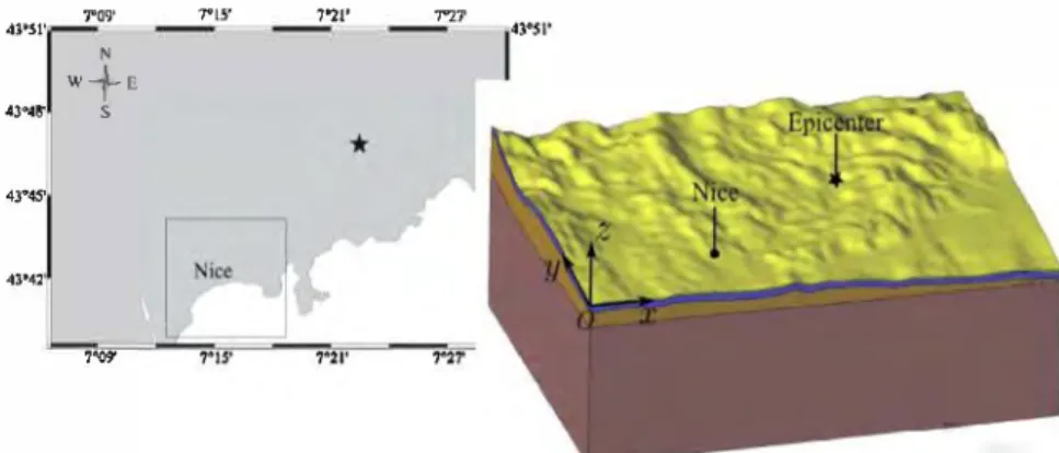
achieving a quantitative seismic hazard assessment. Numerical simulations of seismic wave propagation are an important tool for risk mitigation and damage assessment in future hypothetical earthquake scenarios. We simula te seismic wave propagation from a potential seismic source to a site located on the French Riviera, and the related ground motion response in the vicinity of Nice.
Fig. 13 shows a map of the study area, where the main
metropolitan area of Nice is framed by a rectangular bounding box (left). In the right-hand portion of the same figure, a 3-D view of the study area is shown where topography has been preserved but geology simplified. The size of the area is 30 km x 23 km x 10 km. The GEFDYN software package [34] is used to compute the maximum peak ground velocity [ 35 ]. Severa) hundred processors are used to obtain these data, representing 246 MB and 563 MB of VfK binary files.
We develop several services dedicated to the post-processing of these data. In this case, the most important point is to store the data on the computing facilities in order to process them on the server and only exchange a minimum volume of information between the remote clients. First, the user can either Joad new data on the server or he can choose an existing dataset. A standard VfK filter is proposed in order to clip the database. We used VfK's Python binding for scripting the VfK filter. This script is called
from our platform service with its arguments retrieved from the client.
4.4. Discussion
BRGM, as the French geological survey, must provide public authorities with the necessary tools for natural risk prevention. Engineers are active in more than 40 countries on behalf of governments, public companies, businesses and international funding organizations, whether in a cooperative or an institutional partnership context. Our scenario considers long-distance collab oration between two clients Iocated in Guadeloupe and Martinique (French West-Indies Islands), the server being Iocated in our head office, in Orleans, France. The distance covered by the information from Guadeloupe to Martinique via Orleans is approximately 14,000 km. The client's ease of use is an important aspect conditioning the platform's massive adoption in a large institution.
Figs. 14 and 15 illustra te the client views available to our scientists.
The standard functionalities required to post-process data for tsunami or earthquake modeling are available through the workflow.
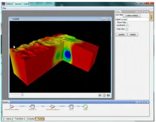
We only describe in detail the results obtained with the seismological service. This is much more significant, as it uses
Fig. 15. A client view devoted ta earthquake modeling.
Rt-6lRr1Pln1ipe - Advî=lm'.;ed PJrl[J 200
100
lq:<lfl n:r,o l'O:M J.0:lD f'D:,n ,o 1(1
Pkt l.OSS: D 1•2\. □ 3·5"ti □ 6•lfl% ■ 11·15"6 ■ 16"-SO"ti ■ 51·95'\s
■
-Qf:i-1GA" UnkrnwnAvg LOSS; 0.60� r1ax Loss; U.0131\
L.atency; Mln: 157.42 ms. Avg; 172.59 rr.s Max; 197.94 ms Dev;
A\'-Q L..at�ncy; ■ □
"'
100A.t-Ma rtinique - Advanced Ping
J(,f:t,tJ lt.l:JU :,O(l:Jlf /IJ:,�ll JU:Jll;I /t):'>ll Pkt Loss: 0 l-2'is □ ]-5"15- � 6-10% ■ 11-15"5 ■ 16-50� ■ '51-95'is
■
!l'5• ]0[l't; U11kttJ\IIIIAvg Loss: (LOO\; Max Loss: tl.li)@\;
Latency: llrn: 190.G<I s Avg: 221.6@ ms Ma,: 352.22 ms Oev:
Avg Latency:
■
□Fig. 16. Network latency for Guadeloupe and Martinique.
200000
100000 250000
Os 10, 20, o, lOs 20s 30s
Without manipulations White manipufating
Fig. 17. Client/server communication data flow rate (bits/sec) without manipulations (left) and with manipulations (right).
3D collaborative interactions and produces large X3D files. The impact of the network performance (latency and contention) could be easily evaluated. The network latency for our test case is about 400 ms; this appears to be good enough for the collaboration (negligible latency between Martinique and Guadeloupe, as shown
in Fig. 16). The minimum bandwidth used by basic client/server
communications (i.e. without manipulation by the operator) is nearly constant, ranging from 120 to 140 kbits/s. This is caused by data exchanges required to guarantee the synchronization between the two clients. With manipulations by the operator, it can reach 270 kbits/s, which is still reasonable for existing
networks (Fig. 17). This limited increase of the traffic rate during the collaborative phase results from the design of the platform. In our case, very little data (position of the camera, ... ) are exchanged when the mode! is manipulated.
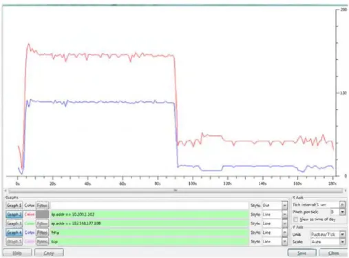
Fig. 18 provides the detail of the traffic between the clients in
Martinique and Guadeloupe and the server located in Orleans. One client manipulates the whole 3D mode! in order to analyze the outputs of the simulation in collaboration with the distant team. The scientists communicate by telephone. The red curve describes ail the network traffic and the blue one represents only the HTTP content (we choose here to encapsulate client/server traffic with
....
,,...lç.,o1,1)c-�
Gt J Ci;,i,ot� if..«I,�� IOJ(W)J.JOl
hil·,1d � ..,.addr .. 1.!12.Ui&..171.108 G, ... � ... r.::;;;:;J.r,;;;:;i.,. � � eo, 100. ''°'
,..,
-"'"
�Lrq-
""
·
��r"t � Lffl�...
1$, ]li>,...
g r.• .. -•., =,--ffi
1
-�
...
�f-u�ollM)'-
'
.
/Ur.c �fU/TIO: .. Sicilt. j�!Jto ��Fig. 18. JO analysis using wireshark: resuming an existing session. First the client loads the X3D file, then we manipulate the 3D mode!.
HTIP protocol ). The initialization of the collaboration process is the most costly phase, more than 80 s being required to upload the mode! from Orleans. Subsequently, the main phase of collabora tion with co-manipulation of the mode! generates a very low level of traffic.
The benefits accruing from a cloud-based platform able to provide smooth accesses to large-scale computing data and collaborative analysis tools are tremendous. The architecture we have described in Section 3 meets these requirements, with the opportunity to share data and knowledge. The deployment of this platform is not only a means to save computing resources by rendering the use of the centralized cluster easier. The impact is also in terms of management of human resources, as an emergency meeting can be conducted remotely by confronting several opinions based on the same data. The experiment we have conducted clearly demonstrates the feasibility of this organization of research teams. Considering the feature that replays selected exchanges between distant experts, such collaborative strategies strengthen knowledge-based sustainability.
Concerning standard network capabilities, we have observed smooth access to large-scale data produced by a seismic wave propagation simulation computed on several hundreds of pro cessors.
5. Conclusion
This paper discusses an open platform for collaborative simulation, scientific big data analysis and 3D visualization for CAE/D. The service-oriented architecture relies on standard internet technologies and the cloud computing paradigm. We introduce its involved technologies and architecture, its potential benefits and the opportunities it affords. We valida te the platform using it as a support for sustainability in chemical engineering. Furthermore, an industrial sustainability-based application for managing natural resources and the environment is explained and discussed. We take advantage of the cloud to underpin collabora tive simulation and visualization by engineers in different geographic locations. The value brought to the scientific and industrial community is to make remote analysis and collabora tion easily available and scalable. The current collaboration
process within the platform can be enhanced, in particular, by integrating innovative techniques with ICI in the era of web 2.0 as initiated by Hüsig and Kohn [36] and as demonstrated by
Negny et al. [37] for the sustainable management of resources.
A further step is to support this communication through web semantic technologies ( also viewed as the next phase of the web, web 3.0). Zanni-Merk et al. [38] suggest ontology for knowledge acquisition and capitalization in inventive design. In the natural hazard domain, ontologies can help describe such
knowledge [39] and could be integrated into the platform as a
dedicated workflow suited to emergency and disaster manage ment. Remote collaboration in a distributed virtual reality context is another promising avenue to be explored. Preliminary
experiments by Fleury et al. [40] show very promising results
for scientific data analysis. From these perspectives and our current experience of the platform, one big challenge should be to develop a community 2.0 of scientists and engineers, more strongly supported by ICI, dedicated to collaborative scientific simulation and visualization.
Acknowledgment
This work was supported by the French Research National Agency, Program COSINUS, ref: Collaviz-ANR-08-COSI-003
References
[1] OECD, Eco-Innovation in Industry: enabling green growth, Organisation for Economie Co-operation Development report, 2009.
[2] K.W. Brodlie, D.A. Duce, J.R. Gallop, J.P.R.B. Walton, J.D. Wood, Distributed and collaborative visualization, Computer Graphies Forum 23 (2) {2004) 223-251.
[3] I.j. Grimstead, D.W. Waiker, N.J. Avis, Collaborative visualization: a review and taxonomy, in: Proceedings of the 9th IEEE international Symposium on Distrib uted Simulation and ReaI-Time Applications, 2005, pp. 61-69.
[ 4] L. Freitag, P. Knupp, T. Munson, S. Shontz, A comparison of optimization software for mesh shape-quality improvement problems, in: Proceedings of the Eieventh International Meshing Roundtable, 2002, pp. 29-40.
[ 5] R. Gossweiler, R.J. Laferriere, M.L. Keller, R. Pausch, An introductory tutorial for developing muiti-user virtual environments, Presence: Teieoperators and VirtuaI Environments 3 (4.) (1994).
[6] S.K. Chandrasegaran, K. Ramani, R.D. Sriram, I. Horvath, A. Bernard, R.F. Harik, W. Gao, The evolution, challenges, and future of knowledge representation in product design systems, Computer-Aided Design 45 (2) (2013) 204-228.