Time-domain Analysis of Solar Concentrator Structure under
Gust Wind
Bassem Kaabia
a, Sébastien Langlois
a, Sébastien Maheux
a, Frédéric Légeron
ba Department of Civil Engineering, Université de Sherbrooke, 2500 boul. de l'Université,
Sherbrooke, QC, Canada, J1K 2R1
b Vice President, Parsons, Abu Dhabi PO5498, UAE
ABSTRACT: Accurate evaluation of wind load effects on solar structures is important for optimizing their design. Gust wind and its dynamic effect may be significant for this type of structure, however while time-domain numerical simulations are powerful tools to predict the dynamic response, they are rarely used for wind analysis because of the complexity of aerodynamic force models and the difficulty of performing full-scale validations. This paper aims to validate a time-domain dynamic analysis method used to predict the statistical parameters of 10 minute full-scale measurements response of a solar concentrator structure under service wind load conditions. A finite element model of the solar concentrator support was developed and time-domain dynamic (TD) analyses were performed. As a comparison, the acceptability of this method is also revisited in the light of the ASCE 7-10 and the spectral approach prediction. Full-scale measurements and corresponding simulations covered different configurations depending on the pitch angle and loading case. The measured wind speed is converted to drag force, lift force and pitching moment applied to the finite element model. An aerodynamic force model based on the buffeting indicial response function (IRF) associated to the aerodynamic admittance function for flat plate is used for TD analyses of different configurations. Results are compared in terms of statistical parameters, such as the standard deviation and gust effect factors. It was found that, despite the simplified hypotheses taken especially for wind load and structural model, in many cases the proposed approach gives slightly better results for the statistical parameters compared to the spectral approach. Therefore, its overall acceptability is validated. This time-domain approach could then be used to study the linear and nonlinear dynamic structural response of solar concentrator structures under wind load and thus identify optimal design configurations to meet both serviceability and ultimate loading conditions.
KEYWORDS: Finite Element Model, Time-domain Analysis, Wind Load, Solar Concentrator, Spectral Approach, Gust Effect Factor
1 INTRODUCTION
Accurate evaluation of wind loading is a primary concern in optimizing solar structure design. Full-scale measurements are costly solution for the pre-design studies. Wind tunnel investigation, especially conducted in the Sandia Laboratory (Peterka and Derickson, 1992; Hosaya et al., 2008), are well recognized but generalization in quantitative research including dynamic effect is recom-mended (Banks, 2014) (CPP, Inc). Then, there is a strong need for investigations of numerical tools as a cost-effective alternative. Since its development by Davenport (1961), the stochastic spectral approach is the common method to study the response under turbulent wind. A key con-cept developed in this approach is the aerodynamic admittance function, which is inspired by thin airfoil theory (Sears, 1941), and adapted by Davenport (1961) to civil engineering structures. The current standard ASCE 7-10 formulation to predict the equivalent static peak response is developed
based on the early work of Davenport (1961), and it was improved through research such us the work of Vickery (1968), Kareem (1986) and Solari & Kareem (1998). These methods, based on a frequency domain analysis, require significant simplifications in the structural response modeling to represent the complex dynamic behavior. Time domain methods are better to incorporate the non-linear behavior of the structures, and many studies in time-domain have been conducted for various structure types. In many cases, these studies focus on the modeling of wind force in the time-domain. For example, Chen & Kareem (2002) proposed advanced aerodynamic force models applied for long-span bridges. Letchford et al., (1993) evaluated the acceptability of the quasi-steady approach to predict the peak response and RMS values for full-scale low rise buildings at low frequency range. Other time-domain studies looked at the non-linear behavior of certain types of structures. For example, Wegner (2006) and Gani & Légeron (2010) compared the time-domain nonlinear analysis to the standard equivalent static force method for guyed tower structures. Ad-vanced time-domain methods have rarely been used to study the dynamic response of solar struc-tures. Recently, the research group at the Sandia Laboratory were interested in modeling and simulating the dynamic response of a heliostat structure prototype (Zang et al., 2014; Griffth et al., 2014). However, more studies are needed to evaluate the capacity of different analysis methods to predict the global dynamic response of solar structures to turbulent wind. The
The indicial response is the equivalent time domain representation of the aerodynamic admit-tance. Wagner in 1925 first used thin airfoil theory to introduce indicial functions to predict self-excited forces on airfoils. Its application is then extended to bluff body sections where thickness effects, unsteady viscous flow effects and flow separation effect could be more important. It could be also used to model the lift, moment and drag force for both the buffeting and the self-excited components. The expressions of the indicial functions can be derived or approximated via various approaches, such as analytical (Chen & Kareem, 2002; Chang, 2010), computational fluid dynam-ics (Farsani, 2012), or via experimental studies.
The objective of this paper is to present a time-domain method which predicts the dynamic response of solar concentrator prototype under measured gust wind samples and approaches the statistical parameters of the full-scale global response. The acceptability of the method is also reviewed in the light of the results from the equivalent static approach based on the spectral ap-proach.
The present study is composed of two main parts. The first part concerns the description of the numerical model, the time-domain analysis process and the aerodynamic force model. In the sec-ond part, the results are presented in its deterministic description by comparing the measured full-scale base moment measurement and the calculated numerical moment in time-domain. Then, the statistical parameters issued from both frequency and time-domain analyses are compared to meas-urements on a full-scale prototype for over 45 test samples, which were subjected to comparable wind conditions.
2. STUDY DESCRIPTION
2.1. Concentrated Photovoltaic (CPV) Prototype
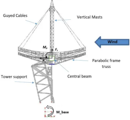
The CPV structure prototype was modeled based on the technical drawings and full 3D model (Fig. 1). For this purpose, Salome-Meca, an open-source simulation platform related to the finite element solver Code Aster, was used. The geometry was composed of three principal parts. First, a double guyed mast is used as a support of the Dense receiver array (DRA). Second, the dish reflector surface is composed of 128 mirrors and a parabolic frame truss supporting structure.
Third, the tower support structure is a truss structure, which is mainly composed of six L203*102*13 section members, and an azimuth motor drive which is fixed to the ground. The HSS 200*200*9.5 torque central beam rests on the tower with two actuators fixed on both sides of the central beam through two roller bearings supported by two vertical rigid plates. The central beam can turn around the transversal X axis by moving the actuators to get the target elevation 𝛾°. This beam is also considered as the primary load transfer element between the dish frames and the tower supporting structure by principally resisting to induced torque and bending moment. The total weight of the CPV prototype is approximately 135 kN.
Figure 1. Side view of the CPV structure prototype (3D CAD model).
2.2. Measurement of structure response
Twelve Linear Variable Differential Transformer (LVDT) sensors were installed on the structure. They were attached by pairs to each of the six main tower members. Compression and tension forces are calculated from displacement for each member. The current configuration was used to calculate a global instantaneous base moment in the along wind direction (Fig. 1). The total mo-ment is calculated as a sum of the product of the forces in each member by its distance from the base center. Simultaneously, the wind characteristics were measured using four ultrasonic ane-mometers. The first and the second anemometers were fixed at 7.5 and 10 m height on the reference tower located at 28 m in the S-W direction from the center point of the prototype. The third and fourth anemometers were fixed at 10 m height on two towers located respectively at 10 m North and 10 m South from the reference tower. The recorded data were treated by 10 min samples with sampling frequency of 20 Hz. Force and moment aerodynamic coefficients are deduced at different
prototype configurations. The measurements were taken in different pitch angle 𝛾 and different wind characteristics. The detailed description of the experimental program methodology and the main results are given in Kaabia et al., (2017). In this paper, only the configurations in which wind direction is perpendicular to the normal axis to dish collector were analyzed (Fig. 1).
2.2.Numerical Modeling
In this part, two modeling strategies were tested. The first consist of modeling the complete CPV prototype. All the structure components (masts, the parabolic frame truss and the supporting tower truss) were modeled as beam elements. The mirrors were modeled by rigid elements, representing only the part where they are attached to the ribs. The cables were also modeled by beam elements with initial tension applied as a temperature gradient. Fixed boundary conditions were assumed at the tower base. Steel material properties were assigned to all parts of the structure except for the mirrors for which the density of the rigid elements was adjusted to represent the total mass of the mirrors. The supporting tower members were rotated in such a way that they respect the actual orientation of the tower members. The elevation bearing mechanism was modeled as discrete spring element having only one rotational degree of freedom around the central beam (X axis). Because, it was found difficult to quantify the stiffness of the elevation bearing mechanism, spring rigidity was calibrated to obtain the main measured natural frequencies. To do that, the two main natural frequencies at 1.0 and 3.8 Hz, corresponding to the pitching and swaying mode shapes were chosen from the PSD (Power Spectral Density) of the measured base moment for many test samples.
The second strategy consisted in modeling only the supporting tower, the central beam and the drive mechanism. It was assumed that the rest of the structure (parabolic frame and mast) could behave like a rigid body. Then, the entire weight of the parabolic dish collector and masts (~68 kN) was distributed uniformly along the central beam length. Discrete mass elements were affected to the central beam node, where elementary mass matrix including the mass and the mass moment of inertia values with respect to the eccentricity, were assigned.
2.3. Model Simplification and Modal Analysis
Preliminary modal analyses were conducted for the complete structure at different elevation an-gles. The analysis resulted in a high number of global and local mode shapes. Only a few of them in the low frequency range could be excited and thereby induce an important structural dynamic response at the tower base in the studied along-wind-direction case. For example, based on Dav-enport (1961), pitching and swaying mode shapes are the most important to be considered for such type of structure. Therefore, it would be of interest to simplify the structure as mentioned in the second modeling strategy. In order to validate this simplified model, a modal analysis was con-ducted for both the complete and simplified model. It was found that the pitching and swaying mode shapes, corresponding respectively to the rotation of the dish collector (Fig. 2a) and the displacement of the tower in the along wind direction (Fig. 2b) were observed at 1.0 and 3.8 Hz for both models. In order to achieve the objective of studying the global response at the base tower in the along wind direction, it was decided to use only the simplified model for the rest of the study.
Figure 2a. Pitching mode shape (f1=1.0) Figure 2b. Swaying mode shape (f2=3.8) Figure 2. Modal analysis in Code_Aster : principal mode shapes.
2.4. Time Domain Method
Newmark direct integration scheme with coefficients 𝛽 = 0.25, 𝛼 = 0.5 was used for the time-domain analysis. This implies that no numerical damping is introduced into the numerical integra-tion. The time step was set to 0.05 s which is equivalent to the experimental sampling period. This gives about 20 calculations per eigen-period for the first mode shape, which ensures that the rela-tive period error is small. The total wind load components including drag and lift forces as well as pitching moment were calculated from the wind speed test samples. Then, they were uniformly distributed through the central beam nodes.
2.4.1. Damping Considerations
The structural damping was included in this study using Rayleigh damping by fixing the structural damping ratio of two chosen natural frequencies 1.0 and 3.8 Hz, corresponding to pitching and swaying mode shapes, to values of ξ=0.25% and ξ =0.1%, respectively. The values were based on the recommendations of Davenport (1964) for a parabolic antenna structure with a similar geom-etry. It also appears realistic when compared to the experimental study of Griffth et al., (2014). Aerodynamic damping (C) was evaluated according to the quasi-static theory as proceeded in Gani & Légeron (2010) where the aerodynamic damping is evaluated using the simplified formulation. The aerodynamic damping values were introduced as discrete concentrated dampers for drag, lift and moment and distributed equally on the central beam nodes where the wind loads were applied. Eq. 1 present the applied aerodynamic function for the drag force.
𝐶 = 𝜌𝑎𝑖𝑟𝐶𝑑𝑈̅𝐴 (1) where 𝜌𝑎𝑖𝑟 is the air density, 𝑈̅ is the mean wind speed, 𝐴 is total dish area and 𝐶𝑑 is the drag force coefficient used to evaluate the aerodynamic damping for the swaying mode case.
2.4.2. Aerodynamic Force Model
This study is concerned with the prediction of the maximum probable response of the CPV proto-type in the along-wind direction. It is conventional to separate the along-wind force into buffeting
and self-excited forces. In this paper, it is assumed that the most important component is related to the buffeting forces, and the self-excited force is simply considered by introducing the aerody-namic damping as mentioned in the precedent subsection. The time-domain varying wind load components including drag and lift forces as well as pitching moment were calculated from the wind speed test samples. Then, they were uniformly distributed through the central beam nodes. The lift and moment aerodynamic coefficients used here were evaluated from wind tunnel meas-urements made by Gani et al., (2011). The drag force coefficients were adjusted according to full-scale measurements on the CPV prototype (Kaabia et al., 2017). The forces in the main supporting tower members are extracted from the numerical analysis and the global base moment is calculated with the same methodology as for the experimental base moment. In addition, it is found that the plate is the form that comes closest to the parabolic dish geometry, for which the experimental aerodynamic admittance was evaluated in the past (Davenport, 1961; Vickery, 1968). The larger the focal ratio 𝑓/𝐷, the more solar structures behave like flat plates. Then, the approximate form of the aerodynamic admittance function for buffeting along wind force could be presented as fol-lows:
𝜒𝑎2(𝑛) = ⎸𝛷(𝑘)⎸2 = 1
(1+𝑘)4/3 (2)
𝑘 =𝑛𝑐
𝑈 (3) where 𝜒𝑎2(𝑛) is the aerodynamic admittance function, 𝛷(𝑘) is Sears' function, 𝑘 is the re-duced frequency, 𝑛 is the frequency. The variable 𝑐 is defined as the characteristic scale length taken equal to √𝐴, the square root of the projected area of the dish collector depending on its elevation angle. Theoretically, this characteristic length, as compared to the wind wave length, could define how important is the correlation between wind speed and the induced aerodynamic wind force.
The need to use the aerodynamic admittance function concept in time-domain analysis gave rise to the indicial response function (IRF) approach. This time-domain aerodynamic force mod-eling approach represents a modified form of the quasi-steady nonlinearized approach QS as re-viewed in Scanlan (1993) and Chen & Kareem (2002) in the modeling of wind force applied to bridge decks. The non-correlation between turbulent wind speed and the induced force, which is not considered with the quasi-steady model (QS), is mathematically presented with the convolu-tion product where the participaconvolu-tion of the precedent turbulent wind speed values in the current wind force are weighted according to the IRF form as shown in equations 4-7. The turbulent lift force and the turbulent pitching moment would be formulated in a similar way.
𝐹(𝑡) = 𝐹̅ + 𝑓(𝑡) (4) 𝑓(𝑡) = 𝜌𝑎𝑖𝑟𝑈̅𝐴𝐶𝑓𝑥∫ [𝑢(𝑠) − 𝜑′(𝑠 − 𝜎)] 𝑠 0 𝑑𝜎 (5) 𝜑′= 0.075𝑒−0.513 𝑠+ 1.794𝑒−2.111𝑠 (6) 𝑠 = 𝑈̅𝑡/√𝐴 (7)
As formulated, the total drag force 𝐹(𝑡) is linearized to be composed of mean 𝐹̅ and turbulent parts 𝑓(𝑡). 𝜑′ is the derivative of the indicial function 𝜑 for flat plate, 𝑠 is the nondimensional
time. The derivative of the indicial function 𝜑′ for a flat plate is already evaluated in Chang (2010).
2.5. Statistical Dynamic Parameters
The measured moment at the base is the reference parameter to be evaluated in the numerical work. It is considered that the along-wind response is coming from the pitching moment 𝑀𝑝 and the
drag force 𝐹𝑥. Then the overturning base moment could be deduced from Eq. 8.
𝑀 = 𝐹𝑥 . 𝐻 + 𝑀𝑝 (8) Where 𝐻 is the height of the central beam.
The study focuses especially on comparing the peak response from the experimental and nu-merical results. Therefore, as is presented in its basic formulation in the literature, the gust effect factor 𝐺𝐸𝐹, a key dimensionless parameter to separate the peak response in its background and resonance form from the static gust wind effect, is calculated in Eq. 9.
𝐺𝐸𝐹 =𝑀𝑚𝑎𝑥/𝑀̅̅̅
𝐺𝑣 2 (9)
where 𝑀𝑚𝑎𝑥 and 𝑀̅ are respectively the maximum and the 10-min time average moment and
𝐺𝑣 is the wind gust factor based on 3-s gust duration in order to fit the ASCE 7-10 current formu-lation (ASCE 7-10).
In this study, three force modeling methods in time-domain including QS, IRF and a modified QS issued from Lawson's TVL formula (Lawson, 1980) using a 0.3-s moving average wind speed as a size reduction filter were tested. In frequency domain, Davenport's spectral approach in its basic form (Davenport, 1961) and ASCE 7-10 method are implemented and validated. All param-eters in ASCE 7-10 as well as Davenport's spectral approach were adapted to the CPV prototype geometry and to the measured wind characteristics, including wind spectrum, turbulence intensity and peak wind factor, for each test sample. The ASCE 7-10 is applied by only including the first mode shape as it is recommended by the code. Then, the peak response factor 𝑔𝑟 is calculated using only the first natural frequency. The hypothesis and the procedure are detailed in (Kaabia et al., 2017). However, the Davenport's spectral approach is adapted to calculate the statistical pa-rameters related to the base moment response for 10-min duration by including the two principal mode contributions. It is considered that the along-wind maximum response is coming from the pitching moment 𝑀𝑝 and the drag force 𝐹𝑥. The peak value of 𝑀𝑝 and 𝐹𝑥 do not occur at the same time because they are caused by different flow conditions. Then, it was calculated using the square-root-of-sum-of-squares (SRSS) combination method. The measured wind spectrum is also used for this application. The summary of the mathematical model and the hypothesis is detailed in the following paragraph.
Assuming that wind speed and consequently wind response are stationary random series fol-lowing the normal stochastic law (Davenport, 1961), the peak moment response and the 𝐺𝐸𝐹 are then evaluated in Eqs 10-13.
𝜎𝑀 = 𝜎𝐵+ 𝜎𝑅 (11) 𝐺𝐿𝐹 =1+√𝑔𝑣2𝜎𝐵2+𝑔𝑟2𝜎𝑅2 𝑀̅ (12) 𝐺𝐸𝐹 =𝐺𝐿𝐹 𝐺𝑣 2 (13) Where 𝑔𝑣 is the quasi-static peak response factor or the wind peak factor. 𝑔𝑟 is the resonance peak factor, which is calculated using the extremum statistics law (Davenport, 1961) for a duration T=600 s. 𝜎𝐵, 𝜎𝑅 are the standard deviation for the quasi-static and the resonance response. 𝜎𝐵 was evaluated as the area under the analytical response spectrum (PSD) by ignoring any dynamic effect. 𝜎𝑅 was evaluated by considering a narrow band response at the natural frequency. It was
also more coherent to split the total peak factor 𝑔 into terms 𝑔𝑣 and 𝑔𝑟. This procedure was separately applied for both the drag force and the pitching moment induced response. Then, the combination to get the total response and the statistical parameters was applied.
3. RESULTS AND DISCUSSIONS
3.1.Time domain
This study focuses on determining the maximum base moment response of the CPV prototype subjected to operational wind conditions in a direction coincident with the wind for different con-figurations. However, it is interesting to have information about the complete time history of the studied response and how often peak values could occur in a time period.
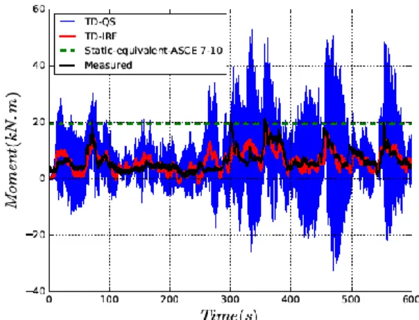
Figs. 3a and 3c present a dynamic time history analysis issued from the QS and IRF approach and compare the results to the measured response for two typical test samples at different config-urations. The constant dashed line illustrates the static equivalent peak values issued from ASCE 7-10 prediction using the evaluated 3-s wind gust. The measured response for two samples display average responses of approximately 7 kN.m and 15 kN.m respectively, with some narrow peaks due to significant gusts. It is also shown that the use of IRF method decreases the important fluc-tuations and the high peaks observed for the QS method, therefore better approaching the measured response.
Figs. 3b and 3d present the PSD calculated from the same test samples. In fig. 3b, it is observed that the graph for the frequency range 0-3.8 Hz is better fitting the measured response for the IRF method. This is consistent with the role played by the indicial response function and the aerody-namic admittance function which attenuates the response above ~0.5 Hz for this case. After this value, the gust becomes ineffective in producing total forces on the structure. The resonant peak at 3.8 Hz also better fits the measured response when using the IRF method. Its frequency peaks are reduced compared to QS method and the standard deviation represented by the surface under the spectrum are better represented. Above ~4 Hz, the simulated response is much lower than the measured response. However, for this frequency the contribution to the global response of the structure is limited. Similar observations can be made from Fig. 3d for the configuration 𝛾 = 90°. The main difference is that the resonant response obtained in the simulations at 3.8 Hz for the swaying mode is much less important in the measurements compared to the pitching mode peak. This may be due to the weak peak contribution of the drag force to the global response in that configuration of the structure. It is concluded that the role played by the IRF in time-domain and
by the aerodynamic admittance in frequency domain seems to be essential to predict the response in high frequency range where the natural frequency could exhibit significant energy. On the other hand, the dynamic effect coming from the pitching mode at 1.0 Hz is more important for the con-figurations 𝛾 close to 90°, where the turbulent pitching moment is higher and the wind spectrum energy is more important.
Figure 3a. Instantaneous base moment Figure 3a. Normalized PSD
Figure 3c. Instantaneous base moment Figure 3d. Normalized PSD
Figure 3. Comparison of measured and simulated moment response for two typical samples at pitch angle 𝛾 = 0° and 𝛾 = 90°.
3.2.Statistical parameters comparison
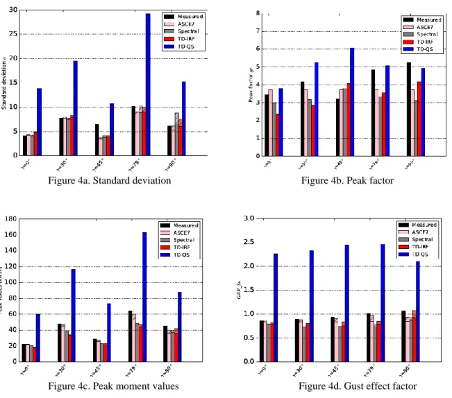
The statistical study was carried out for 45 test samples in order to calculate the conformity be-tween values derived from the full-scale measured data and the simulated data. The ratios bebe-tween simulated and measured values were calculated for each test and 𝐸 represents the average of these ratios over all tests and 𝜎𝐸 is the standard deviation for this ratio. The results are summarized in Table 1. Moreover, five typical test results representing the five tested configurations are shown in Fig. 4. In this figure, the dynamic contribution in the total response is highlighted in lighter hatched color. The dynamic contribution part for each parameter was calculated as a difference
between the results from the total dynamic response and the response issued from a time-depend-ing static analysis ustime-depend-ing the turbulent wind loadtime-depend-ing.
Figure 4a. Standard deviation Figure 4b. Peak factor
Figure 4c. Peak moment values Figure 4d. Gust effect factor Figure 4. Comparison of different methods in predicting response statistical parameters.
Table 1. Comparison between the calculated statistical parameters from the measured and simulated base moment using different methods
Parameters
Spectral stochastic TD
ASCE7-10 Davenport QS Lawson’s TVL IRF
E 𝜎𝐸 E 𝜎𝐸 E 𝜎𝐸 E 𝜎𝐸 E 𝜎𝐸
𝜎𝑀 0.85 0.14 0.99 0.16 2.50 0.65 1.81 0.49 0.98 0.24
𝑔 0.86 0.26 0.84 0.22 1.17 0.31 1.15 0.30 0.82 0.20 𝐺𝐸𝐹 0.96 0.18 0.88 0.15 2.38 0.69 1.79 0.43 0.92 0.20
For this final comparison, all the results relating to the base moment, shown in Table 1, were summarized. In general, good agreement and similar results could be observed for the standard deviation, the peak factor and the gust effect factor of the time-domain analyses based on the IRF, the spectral approach and the ASCE 7 formulation. The ASEC 7 and the spectral approach results are always within the limit of E ± 𝜎𝐸 from those of the IRF analyses. Table 1 shows also that, in
term of standard deviation values, the background and the resonance response are better repre-sented by the aerodynamic admittance function and the IRF used for the Davenport’s spectral ap-proach and the time-domain method, respectively. The ASCE 7 prediction slightly underestimates this value because of its less conservative aerodynamic admittance function compared to flat plate. However, the QS approach highly overestimates the standard deviation for all tests which leads to high discrepancies in predicting the maximum values. In term of peak factor values, more discrep-ancies are recorded between the investigated methods and the experimental results. It seems that the statistical extrema law introduced to calculate the response factor 𝑔𝑟 could contribute in slightly underestimating the peak values for the study of loading cases at service conditions (see Fig .4b).
Overall, it is observed in Table 1 that the IRF method was successful to predict the GEF and the standard deviation of the base moment response. The results of the IRF method are coherent with both Davenport's spectral approach and ASCE 7 prediction and by far better than the QS prediction which is overestimating the peak response for all test samples. It was also investigated that applying the Algebric Combination (AC) instead of the Square-Root-of-Sum-of-Squares (SRSS) for the Davenport's spectral approach, could improve the prediction of the GEF and there-fore the peak value by 8% in average. However, the time-domain method is still the most efficient to include correctly the mode shape interaction effect.
It is shown in Figure 4c, that depending on the CPV structure configurations and the wind loading cases, the peak equivalent static response calculated from Davenport’s spectral approach or ASCE 7 formulation and the maximum response calculated with the IRF may underestimate or overestimate slightly the possible dynamic response. However, QS approach highly overestimates the total response for all tests. For example, it is shown in Fig. 4a that the dynamic contribution in the standard deviations for QS seems to be out of range and could represent more than about ~50% of the total response for all the selected tests. Therefore, it is confirmed that the filtering role played by the IRF in time domain and the aerodynamic admittance in the frequency domain is successful to evaluate the turbulent response and its dynamic part for this type of structure under service wind conditions. In fact, the unsteady events like flow separation which could be important for this type of structure with a complex aerodynamic profile don’t have an instantaneous effect on the body surface. Then, the quasi-steady theory may not be applicable for the prediction of aerodynamic forces in separation regions as investigated in Tieleman (2003). It is also noted that neglecting the second order turbulence effect by linearizing the total force formulation could contribute to reduce the mean value of the calculated time-domain response. This could explain that the spectral ap-proach may give higher peak value compared to the IRF method in Fig. 4c. Then, the GEF is a more consistent parameter to compare the dynamic effect in its normalized form (Fig .4d).
In the same figure, the dynamic part contribution could slightly vary depending on the method for the same test configuration. This point is also confirmed from the previous statistical compar-ison, and it is found that the contribution of the dynamic part in the peak response for all test samples, in terms of GEF, varies between 0 and 22% for IRF, between 0 and 8% for Davenport's spectral approach, and between 1 and 21% for ASCE 7. It is also observed that dynamic effect is likely to be significant for the configurations around the 𝛾 = 90° when the pitching moment is important. The non-consideration of this pitching moment with its turbulent component in the nu-merical analysis could lead to high errors for this type of structure.
It is concluded that the IRF could be confidently used in time-domain analysis instead of the QS as an alternative to the common frequency domain methods. It is also observed that the dy-namic effect contribution could be important in the design of such special structures at security position for high wind conditions and the dynamic contribution could be well predicted using the IRF method. The spectral approach give also a coherent result in predicting statistical dynamic
parameters. However, it could be sensible to dynamic structural mode interaction and its results alone gives no indication about how often peak values could occur in a period of time.
4. CONCLUDING REMARKS AND FUTURE WORK
The present study is the continuation of previous full-scale work for which the wind speed and the base moment of a CPV prototype were measured instantaneously. This paper shows the results of a deterministic time-domain analysis of the CPV prototype numerical model. It compares this time-domain method to common frequency domain methods as well as full-scale measurements. A statistical comparison study over many test samples has shown that time-domain method, using indicial function derived for a flat plate and applied to the simplified CPV numerical model, can predict with acceptable variation the statistical parameters of the global wind response. The im-portance of possible dynamic effects caused by the turbulent wind could vary depending on wind cases and structure configurations. It is observed that, even though the drag force is not very im-portant for positions near to the security position at 𝛾 = 90°, the pitching moment could lead to important dynamic effects.
The methodology developed here is a simplified tool to obtain the global response of a solar structure. Important simplifications were made regarding the dynamic behavior of the CPV proto-type, for the structural behavior of the cables and dish collector. The across-wind response which could be caused especially by vortex shedding was not considered, owing to the difficulty to per-form a validation procedure. Moreover, the proposed method simplifies the aerodynamic force caused by the complex fluid flow around the structure. Nonetheless, the proposed simplification hypotheses could be advantageous for engineering design application for such type of structures. A simplified time-domain method could be effectively used to extend the study for design condi-tions where high wind speed cases and nonlinearities could be included. It could be also used to conduct parametric study to evaluate the effect of wind and structural parameters to meet optimal design criteria for similar structures under wind load.
5. ACKNOWLEDGEMENTS
The authors would like to thank SpaceWatts division of Gestion TechnoCap for the technical contributions and financial support for the research, along with NSERC, PROMPT and Hydro-Sherbrooke. We are also grateful for the financial contributions of the Canadian Foundation for Innovation (FCI), the Ministère de l’Économie, Science et Innovation of Québec and the Université de Sherbrooke for the unique CPV infrastructures. Finally, the technical contribution of M. Richard Norman for the work related to the CPV prototype is greatly acknowledged.
6. REFERENCES
1 ASCE7-10, Minimum Design Loads for Buildings and other Structures. ASCE, Reston, VA, 2010. 2 Chang, B., Time-Domain Model for Predicting Aerodynamic Loads on a Slender support structure for
fa-tigue design, Journal of Engineering Mechanics, 2010, 136 (6), 736-746.
3 Chen, X., Kareem, A., Advances in Modeling of Aerodynamic Forces on Bridge Decks, Journal of Engi-neering Mechanics, 2002, 128 (11), 1193-1205.
4 Davenport, A., The Application of Statistical Concept to the Wind Loading of Structures, Journal. I.C.E, 1961.
5 Davenport, A., Buffeting of Large Superficial Structures by Atmospheric Turbulence, Proceedings of the Conference on Large Radio Antennas. Annuals of New York Academy of Sciences, 1964, 116, 11-34. 6 Banks, D., How Wind Load Studies will Impact the Solar Industry, Fort Collins, 2014.
7 Farsani, H. Y., Indicial Function Predictions of Two Dimensional Unsteady Viscous Flows Around Bluff Bodies Based on Discrete Vortex Simulations, 2012.
8 Gani, F., Légeron, F., Dynamic Response of Transmission Lines Guyed Towers Under Wind Loading, Ca-nadian Society of Civil Engineering, 2010, 37, 450-464.
9 Gani, F., Légeron, F., Norman, R., Refinement of Design for Parabolic Truss Structure for Solar Concen-trating Photovolataic Tracker System, Annual Conference of the Canadian Society of Civil Engineering, 2011, 788-799.
10 Griffth, T. D., Moya, A. C., Ho, C. K., Hunter, P. S., Structural Dynamics Testing and Analysis for Design Evaluation and Monitoring of Heliostats, Journal of Solar Energy Engineering, 2014, 137 (2), 21010. 11 Hosoya, N., Peterka, J. a., Gee, R. C., Kearney, D., Wind Tunnel Tests of Parabolic Trough Solar
Collec-tors. Tech. rep., National Renewable Energy Laboratory, 2008.
12 Kareem, A., Synthesis of Fluctuating Along-Wind Loads on Tall Buildings, Journal. Mech. Div., ASCE, 1986, 112(1), 121-125.
13 Lawson, T., Wind Effect on Buildings, Applied Science Publishers Ltd.1, 1980.
14 Letchford, C. W., Iverson, R. E., McDonald, J. R., The Application of the Quasi-Steady Theory to Full Scale Measurements on the Texas Tech Building, Journal of Wind Engineering and Industrial Aerodynam-ics, 1993, 48 (1), 11-132.
15 Peterka, J.A., and Derickson, R.G., Wind Load Design Methods for Ground Based Heliostat and Parabolic Dish Collectors, Sandia National Laboratories, 1992.
16 Scanlan, R. H., Problematics in Formulation of Wind Force Models for Bridge Decks, Journal of Engineer-ing Mechanics, 1993, 119 (7), 1353-1375.
17 Sears, W., Some Aspects of Non-Stationary Airfoil Theory and its Practical Application, Journal. Aero. Sci, 1941, 8(3), 104-108.
18 Solari, G., Kareem, A., On the Formulation of ASCE7-95 Gust Effect Factor, Journal of Wind Engineering and Industrial Aerodynamics, 1998, 77-78, 673-684.
19 Sparling, B. F., Wegner, L. D., Comparison of Frequency and Time-domain Analyses for Guyed Masts in Turbulent Winds, Canadian Society of Civil Engineering, 2006,182, 169-182.
20 Tieleman, H. W., Wind Tunnel Simulation of Wind Loading on Low-rise Structures : A review, Journal of Wind Engineering and Industrial Aerodynamics, 2003, 91(12), 1627-1649.
21 Vickery, B., The Application of Statistical Concept to the Wind Loading of Structures, Journal. Eng. Mech. Div., ASCE, 1968, 94(1), 31-46.
22 Zang, C., Christian, J., Yuan, J., Sment, J., Moya, A., Ho, C., Wang, Z., Numerical Simulation of Wind Loads and Wind Induced Dynamic Response of Heliostats, Energy Procedia 49, 2014, 1582-1591.