UNIVERSITÉ DE MONTRÉAL
INTRA-OPERATIVE NEEDLE TRACKING USING OPTICAL SHAPE SENSING TECHNOLOGY
KOUSHIK KANTI MANDAL
DÉPARTEMENT DE GÉNIE INFORMATIQUE ET GÉNIE LOGICIEL ÉCOLE POLYTECHNIQUE DE MONTRÉAL
MÉMOIRE PRÉSENTÉ EN VUE DE L’OBTENTION DU DIPLÔME DE MAÎTRISE ÈS SCIENCES APPLIQUÉES
(GÉNIE INFORMATIQUE) MARS 2016
UNIVERSITÉ DE MONTRÉAL
ÉCOLE POLYTECHNIQUE DE MONTRÉAL
Ce mémoire intitulé:
INTRA-OPERATIVE NEEDLE TRACKING USING OPTICAL SHAPE SENSING TECHNOLOGY
présenté par : MANDAL Koushik Kanti
en vue de l’obtention du diplôme de : Maîtrise ès sciences appliquées a été dûment acepté par le jury d’examen constitué de :
M. LANGLOIS J. M. Pierre, Ph. D., président
M. KADOURY Samuel, Ph. D., membre et directeur de recherche M. MARTEL Sylvain, Ph. D., membre et codirecteur de recherche M. LEBLOND Frédéric, Ph. D., membre
ACKNOWLEDGEMENTS
First and foremost, I would like to express my deepest appreciation to my supervisor, Professor Samuel Kadoury, for his guidance, encouragement and the pieces of advice during my graduate studies.
I would like to thank my co-supervisor Professor Sylvain Martel sincerely for giving me the opportunity to work and share the resources in his lab.
I wish to thank Professor Raman Kashyap for sharing his expertise on fiber Bragg gratins in this project.
I would like to say a big "thank-you" to all my colleagues at the “MEDICAL Lab”, “APCL Lab” and "NANOROBOTICS Lab" who shared knowledge, wisdom and joy with me. Special thanks go to François Parent for the fiber fabrication and Eric Hideki Watanabe Fernandes for helping me in taking measurements during the experiments.
I wish to thank the jury members: Professor Pierre Langlois and Professor Frédéric Leblond for their valuable time and interest in reading this thesis.
Last but not the least, I am deeply grateful to my parents, for their unconditional love and support.
RÉSUMÉ
Contexte : Les métastases hépatiques colorectales sont la principale cause de décès liée au cancer du foie dans le monde. Au cours de la dernière décennie, il a été démontré que l’ablation par radiofréquence (RFA, pour radiofrequency ablation) est une méthode de traitement percutané très efficace contre ce type de métastases. Cela dit, un positionnement précis de l’embout de l’aiguille utilisé en RFA est essentiel afin de se départir adéquatement de la totalité des cellules cancéreuses. Une technologie prometteuse pour obtenir la forme et la position de l’aiguille en temps réel est basée sur l’utilisation de réseaux de Bragg (FBG, pour fiber Bragg grating) à titre de senseur de contrainte. En effet, ce type de senseurs a une vitesse d’acquisition allant jusqu’à 20 kHz, ce qui est suffisamment rapide pour permettre des applications de guidage en temps réel. Méthode : Les travaux présentés au sein de ce mémoire décrivent le développement d’une technologie, compatible aux systèmes d’imageries par résonance magnétique (IRM), permettant d’effectuer le suivi de la forme de l’aiguille utilisée en RFA. Premièrement, trois fibres contenant une série de réseaux de Bragg ont été collées dans une géométrie spécifique et intégrées à l’intérieur d’une aiguille 20G-150 mm. Ensuite, un algorithme de reconstruction de forme tridimensionnelle a été développé, basé sur les mesures de translation spectrales des FBGs acquises en temps réel durant le guidage de l’aiguille. La position du bout de l’aiguille ainsi que la forme tridimensionnelle complète de celle-ci ont été représentées et comparées à la position de la zone ciblée à la suite d’une simple méthode de calibration. Finalement, nous avons validé notre système de navigation en effectuant une série d’expériences in vitro. La précision du système de reconstruction tridimensionnelle de la forme et de l’orientation de l’aiguille a été évaluée en utilisant deux caméras positionnées perpendiculairement de manière à connaitre la position de l’aiguille dans le système d’axes du laboratoire. L’évaluation de la précision au bout de l’aiguille a quant à elle été faite en utilisant des fantômes précisément conçus à cet effet. Finalement, des interventions guidées en IRM ont été testées et comparées au système de navigation électromagnétique NDI Aurora (EMTS, pour Electromagnétic tracking system) par le biais du FRE (fiducial registration error) et du TRE (target registration error).
Résultats: Lors de nos premières expériences in vitro, la précision obtenue quant à la position du bout de l’aiguille était de 0,96 mm pour une déflexion allant jusqu’à ±10,68 mm. À titre comparatif, le système d’Aurora a une précision de 0.84 mm dans des circonstances similaires.
Les résultats obtenus lors de nos seconds tests ont démontré que l’erreur entre la position réelle du bout de l’aiguille et la position fournie par notre système de reconstruction de forme est de 1,04 mm, alors qu’elle est de 0,82 mm pour le EMTS d’Aurora. Pour ce qui est de notre dispositif, cette erreur est proportionnelle à l’amplitude de déflexion de l’aiguille, contrairement à l’EMTS pour qui l’erreur demeure relativement constante. La dernière expérience a été effectuée à l’aide d’un fantôme en gélatine, pour laquelle nous avons obtenu un TRE de 1,19 mm pour notre système basé sur les FBG et de 1.06 mm pour le système de navigation par senseurs électromagnétiques (EMTS). Les résultats démontrent que l’évaluation du FRE est similaire pour les deux approches. De plus, l’information fournie par les caméras permet d’estimer la précision de notre dispositif en tout point le long de l’aiguille.
Conclusion : En analysant et en interprétant les résultats obtenus lors de nos expériences in vitro, nous pouvons conclure que la précision de notre système de navigation basé sur les FBG est bien adaptée pour l’évaluation de la position du bout et la forme de l’aiguille lors d’interventions RFA des tumeurs du foie. La précision de notre système de navigation est fortement comparable avec celle du système basé sur des senseurs électromagnétiques commercialisé par Aurora. L’erreur obtenue par notre système est attribuable à un mauvais alignement des réseaux de Bragg par rapport au plan associé à la région sensorielle et aussi à la différence entre le diamètre des fibres et celui de la paroi interne de l’aiguille.
ABSTRACT
Background: Colorectal liver metastasis is the leading cause of liver cancer death in the world. In the past decade, radiofrequency ablation (RFA) has proven to be an effective percutaneous treatment modality for the treatment of metastatic hepatic cancer. Accurate needle tip placement is essential for RFA of liver tumors. A promising technology to obtain the real-time information of the shape of the needle is by using fiber Bragg grating (FBG) sensors at high frequencies (up to 20 kHz).
Methods: In this thesis work, we developed an MR-compatible needle tracking technology designed for RFA procedures in liver cancer. At first, three fibers each containing a series of FBGs were glued together and integrated inside a 20G-150 mm needle. Then a three-dimensional needle shape reconstruction algorithm was developed, based on the FBG measurements collected in real-time during needle guidance. The tip position and shape of the reconstructed 3D needle model were represented with respect to the target defined in the image space by performing a fiducial-based registration. Finally, we validated our FBG-based needle navigation by doing a series of in-vitro experiments. The shape of the 3D reconstructed needle was compared to measurements obtained from camera images. In addition, the needle tip accuracy was assessed on the ground-truth phantoms. Finally, MRI guided intervention was tested and compared to an NDI Aurora EM tracking system (EMTS) in terms of fiducial registration error (FRE) and target registration error (TRE).
Results: In our first in-vitro experiment, the tip tracking accuracy of our FBG tracking system was of 0.96 mm for the maximum tip deflection of up to ±10.68 mm, while the tip tracking accuracy of the Aurora system for the similar test was 0.84 mm. Results obtained from the second in-vitro experiment demonstrated tip tracking accuracy of 1.04 mm and 0.82 mm for our FBG tracking system and Aurora EMTS, respectively for the maximum tip deflection of up to ±16.83 mm. The tip tracking error in the developed FBG-based system reduced linearly with decreasing tip deflection, while the error was similar but randomly varying for the EMTS. The last experiment was done with a gel phantom, yielding a TRE of 1.19 mm and 1.06 mm for the FBG and EM tracking, respectively. Results showed that across all experiments, the computed FRE of both tracking systems was similar. Moreover, actual shape information obtained from the camera images ensured the shape accuracy of our FBG-based needle shape model.
Conclusion: By analyzing and interpreting the results obtained from the in-vitro experiments, we conclude that the accuracy of our FBG-based tracking system is suitable for needle tip detection in RFA of liver tumors. The accuracy of our tracking system is nearly comparable to that of the Aurora EMTS. The error given by our tracking system is attributed to the misalignment of the FBG sensors in a single axial plane and also to the gap between the needle's inner wall and the fibers inside.
TABLE OF CONTENTS
ACKNOWLEDGEMENTS ... III RÉSUMÉ ... IV ABSTRACT ... VI TABLE OF CONTENTS ... VIII LIST OF TABLES ...XII LIST OF FIGURES ... XIII LIST OF SYMBOLS AND ABBREVIATIONS... XIX
CHAPTER 1 INTRODUCTION ... 1
1.1 Malignancy of the liver ... 1
1.2 Percutaneous liver cancer treatments ... 2
1.3 Research objectives ... 3 1.4 Thesis structure ... 4 CHAPTER 2 BACKGROUND ... 6 2.1 Liver anatomy ... 6 2.2 Liver cancer ... 7 2.2.1 Hepatocellular carcinoma ... 7
2.2.2 Metastatic liver cancer ... 8
2.3 Treatment of liver cancer ... 8
2.3.1 Resection operation ... 9
2.3.2 Nonsurgical treatment ... 9
2.3.2.1 Ablation therapy ... 10
2.3.2.2 Percutaneous intratumoral injection ... 10
2.3.2.4 Cryoablation ... 11
2.3.2.5 Radiofrequency ablation ... 11
2.4 Summary ... 12
CHAPTER 3 LITERATURE REVIEW ... 14
3.1 Image-guided interventions in liver tumors ... 14
3.1.1 Optical tracking system (OTS) ... 15
3.1.1.1 Working principle of OTS... 15
3.1.1.2 Classification of OTS ... 16
3.1.1.3 Procedural steps with OTS in IGLI ... 17
3.1.1.4 Studies of OTS in IGLI ... 18
3.1.1.5 Advantages of OTS ... 21
3.1.1.6 Disadvantages of OTS ... 21
3.1.2 Electromagnetic tracking system (EMTS) ... 21
3.1.2.1 Working principle of EMTS ... 22
3.1.2.2 Classification of EMTS ... 23
3.1.2.3 Procedural steps in image guided intervention using EMTS ... 23
3.1.2.4 Studies related to EMTS in IGLI ... 25
3.1.2.5 Advantages of EMTS ... 26
3.1.2.6 Disadvantages of EMTS ... 27
3.2 MRI guided interventional procedure ... 28
3.2.1 MRI guided needle interventions ... 28
3.3 Optical sensing technology ... 31
3.3.1 Fiber Bragg Gratings ... 32
3.3.3 Shape sensing ... 33
3.4 Summary ... 38
CHAPTER 4 METHODOLOGY ... 39
4.1 Experimental setup ... 39
4.2 Needle fabrication ... 40
4.3 Acquiring sensor data from the Deminsys© interrogator ... 42
4.4 Calibration procedure ... 44
4.5 Needle shape reconstruction ... 46
4.6 Navigation software ... 47
4.6.1 Real-time visualization of needle profile ... 47
4.6.2 3D Model generation ... 48
4.6.2.1 Planar phantoms ... 48
4.6.2.2 Anatomical gel phantom ... 49
4.6.3 Robotic system for needle translation ... 50
4.6.4 Point-based registration ... 53
4.7 Validation methodology ... 57
4.8 Summary ... 58
CHAPTER 5 RESULTS ... 59
5.1 Needle shape representation in Slicer ... 59
5.2 Connecting NDI Aurora EMTS with Slicer ... 61
5.3 In-vitro experiment with planar phantom-1 ... 64
5.4 In-vitro experiment with planar phantom-2 ... 74
5.5 In-vitro experiment with gel phantom ... 77
CHAPTER 6 DISCUSSION ... 81
6.1 Comparing FBG-based tracking with Aurora EMTS ... 82
6.2 Comparison with other shape sensing methods ... 85
6.3 MRI compatibility ... 86
6.4 Maximum curvature supported by our fiber system ... 88
6.5 Limitations ... 90
6.6 Summary ... 90
CHAPTER 7 CONCLUSION ... 91
LIST OF TABLES
Table 3.1: Classification of MRI guided needle intervention methods with their advantages... ...(light background) and disadvantages (deep background) ... 30
LIST OF FIGURES
Figure 2.1: Segments of the human liver based on Couinaud segments [12]. Used with
...permission. ... 6 Figure 2.2: The image presents the percutaneous radiofrequency ablation (RFA) procedure
...in the liver (image source from [35]). Used with permission. ... 11 Figure 3.1: 3D reconstruction by triangulation for an optical tracking system. Image source:
...http://iotracker.com/indexdaed.html?q=optical_tracking. Used with permission. ... 15 Figure 3.2: Examples of various commercial OTS with (a) active system (NDI Optotrak),
...passive system based on (b) retro-reflective infrared markers (NDI Polaris), (c) ...visible light patterns (Claron MicronTracker), (d) active markers and (e) passive ...markers. Image source: (a), (b), (d), (e) www.ndigital.com and (c)
...http://www.clarontech.com. Used with permission. ... 17 Figure 3.3: Optically tracked surgical tools: (a) active probe, (b) passive probe. (image
...source: www.ndigital.com) (c) an ex-vivo experiment where optical tracking
...markers are attached to a gamma probe and phantom [42].Used with permission. .... 18 Figure 3.4: Application of OTS in the operating room: (a) Polaris localizer camera used to
...track a surgical instrument in an image-guided liver resection procedure [46], ...(b) NDI Vicra, a passive OTS mounted in an operating room [47]. Used with
...permission. ... 19 Figure 3.5: The prototype surgical navigation system, proposed by Lango et al.; various
...surgical tools that could be tracked by the proposed system: (a) a preoperative ...planning pointer that could be used for patient registration, (b) a dedicated ...intraoperative laparoscopic pointer, (c) a video laparoscope, (d) a grasper for ...navigation during resection, (e) a radio frequency ablation probe, (f) a flexible ...ultrasound probe with electromagnetic tracking sensors on the tip [49]. Used ...with permission. ... 20 Figure 3.6: Working volume offered by OTS (a) NDI Polaris and (b) NDI Vicra. (image
Figure 3.7: EMTS working principle. An EM sensor experiences a spatially and ...temporarily varying magnetic field, produced by the field generator, that
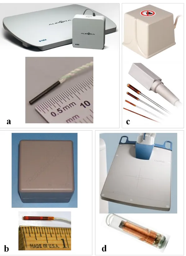
...induces a current in it. ... 22 Figure 3.8: Magnetic field generator and sensors of different commercially available EMTS.
...AC-driven (a) NDI Aurora, (b) Polhemus Fastrak; DC-driven (c) Ascension ...miniBIRD and (d) passive transponder based "Calypso GPS for the body system" ...from Varian Medical System Inc. Image source: (a) www.ndigital.com, (b) ...www.polhemus.com, (c) www.ascension-tech.com, (d) www.varian.com. ...Used with permission. ... 24 Figure 3.9: (A) A common EM tracking procedure with the tracking workstation and a US
...machine for prostate biopsies, (B) EM field generator (circled in blue near the ...top center of image) is placed close to the target and the fiducial patches (yellow ...arrow in center of image) [61]. Used with permission. ... 25 Figure 3.10: A fiber optic cable containing fiber Bragg gratings. ... 31 Figure 3.11: Principle of fiber Bragg grating sensor [74]. Used with permission. ... 32 Figure 3.12: Application principle of FBG sensors for shape sensing in minimally invasive
...surgical tools. ... 34 Figure 3.13: Reconstructed needle shape while the needle was inserted into a soft-tissue
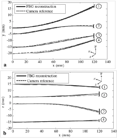
...phantom, (a) top view and (b) side view. Mean tip error for (1) single bend ...(error 1.5±0.8 mm), (2) double bend (error 2.0±0.7 mm), (3) 3D double bend ...(error 2.1±1.1 mm) and (4) drilling insertions (error 1.7±1.2 mm) [80]. ...Used with permission. ... 35 Figure 3.14: 3D Plot of four different fiber shapes, (a) 3D view of the fiber shapes and three
...corresponding orthogonal views, (b) x-y, (c) x-z, and (d) y-z [86]. The green ...line segments indicate Bragg gratings locations. Used with permission. ... 37 Figure 4.1: (a) The complete experimental setup of our FBG-based tracking system, (b)
...calibration plate holding the needle tip inside a groove,(c)three Newport PM500 ...linear stages, (d) two manual linear stages, (e) camera-1 and (f) camera-2. ... 40
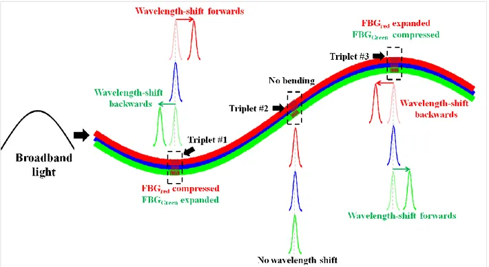
Figure 4.2: 3D shape reconstruction of a needle using the shape sensing technique where ...bending is characterized by the wavelength shift. The left side of the Figure ...shows the orientation of three FBGs at one triplet. The shift of the wavelengths ...λ7, λ8, λ9 occurs due to the bending at triplet #3, while the wavelengths λ1...λ6
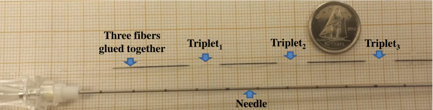
...remain fixed as no bending takes place at triplets #1 and #2 [88]. ... 41 Figure 4.3: Image shows a 20G Spinal needle and three fibers glued together. Each fiber
...includes three FBGs triplets. ... 42 Figure 4.4: A FBG-based needle with three optical fibers having a 120° configuration.
...Each fiber has 3 FBGs placed at three different locations (35, 75 and 115 mm) ...along the needle shaft. ... 42 Figure 4.5: Web server showing the acquisition settings and acquisition control interface. ... 43 Figure 4.6: The overall structure of a UDP packet payload provided by the Deminsys
...interrogator. ... 44 Figure 4.7: During the calibration procedure, the needle tip is stabilized inside the grooves
...(a) without bending and (b) with bending for a known amount of displacement ...of the needle tip. The distance between the successive grooves was 1.4 mm. ... 45 Figure 4.8: Data flow from FBG data acquisition to visualization of shape sensing in
...real-time. ... 48 Figure 4.9: Fabricated planar phantoms, (a) calibration phantom, and (b) validation phantom. ... 49 Figure 4.10: (a) Original gel phantom and (b) the generated model from the preoperative
...MRI image. ... 50 Figure 4.11: Various parts of the robotic system, (a) vertical and (b) horizontal PM500 linear
...stages; (c) rear side of a controller and (d) National Instruments GPIB-USB-A ...Controller for universal serial bus (USB). Image source from: (a-c)
...www.newport.com and (d) https://www.ni.com. Used with permission. ... 51 Figure 4.12: Illustration of the communication between the PM500 system and a computer. ... 52 Figure 4.13: Six multi-modality radiology disk-shaped markers used for the point-based
Figure 4.14: In Slicer, fiducial points were selected at the center of the multi-modality
...radiology disk-shaped markers visible in the MRI DICOM images. ... 54 Figure 4.15: Several landmarks such as grooves and corners were selected as the fiducials. ... 55 Figure 5.1: A line is fitted between the measured wavelength-shift and the strain values
...(calculated from the applied tip bending) to define the calibration matrix. ... 60 Figure 5.2: Slicer interface showing the reconstructed needle shape with two OpenIGTLink
...connectors. ... 61 Figure 5.3: Experimental setup with an Aurora NDI EMTS where the field generator was
...placed close to the needle tip. ... 62 Figure 5.4: Acquiring needle tip tracking information from the NDI Aurora system to Slicer
...through an OpenIGTLink connection. A model in Slicer represents the needle ...tip with orientation. ... 63 Figure 5.5: The interface of the module named, 'Fiducial Registration' in Slicer with its
...input and output parameters. ... 65 Figure 5.6: Real-time visualization of the reconstructed needle shape in Slicer for various tip
...deflections using the planar phantom-1. ... 66 Figure 5.7: TRE is defined as the RMS distance between the actual target location and the
...estimated needle tip position in Slicer. ... 67 Figure 5.8: Accuracy of the estimated needle tip position of our FBG-based tracking at
...various deflections in both (a) xy and (b) xz planes of phantom-1. ... 68 Figure 5.9: Real-time visualization of the EM-based needle navigation in Slicer for various
... tip deflections using planar phantom-1. ... 69 Figure 5.10: Accuracy of the estimated needle tip position of the Aurora system at various
... tip deflections in both (a) xy and (b) xz planes of phantom-1. ... 70 Figure 5.11: The markers on the needle shaft were used to find the needle shape from the
Figure 5.12: Comparison between the physical and approximated needle shape for several ...amounts of tip deflections in the xy plane. The plots show the position of the
...markers on the needle tip along the y-axis. ... 73 Figure 5.13: Real-time visualization of the reconstructed needle shape with its tip position
...in Slicer for various amount of tip deflections using planar phantom-2. ... 74 Figure 5.14: (a) Phantom-2 containing a set of holes and (b) its 3D model, the non-deflected
...needle tip position is shown as a black star, (c) RMS error distribution of the ...needle tip position at various deflections (shown in individual color) for the ...FBG-based tracking system. ... 75 Figure 5.15: Real-time needle navigation with phantom-2 made in plastic in Slicer using
...NDI Aurora EMTS for various tip deflections. ... 76 Figure 5.16: (a) Phantom-2 made of plastic containing a set of holes and (b) its 3D model,
...the non-deflected needle tip position is shown as a black star, (c) RMS error ...distribution of the needle tip position at various deflections (shown in individual ...color) for the Aurora EMTS. ... 76 Figure 5.17: Needle navigation through various tubes of a gel phantom. The reconstructed
...needle shapes (shown in blue color) were well inside the segmented tubes. ... 78 Figure 5.18: Needle navigation using the Aurora EMTS through different tubes of a gel
...phantom. ... 79 Figure 6.1: (a) The plastic model of the phantom-2 where white arrows show the distorted
...holes. (b) 3D model of the phantom-2. ... 83 Figure 6.2: (a) A needle orientation for which the tip was not tracked by the Aurora system,
...(b) the tip position (indicated by arrows) is shown well inside the working
...volume in NDI tool tracker interface. ... 84 Figure 6.3: Side-by-side physical dimension comparison between a Deminsys© interrogator
...and an Aurora field generator with its system control unit. ... 85 Figure 6.4: Image shows the fibers placed inside the bore of a 1.5T MRI scanner. ... 87
Figure 6.5: The calculated strain of all the FBG sensors both (a) inside and (b) outside ...the MRI. ... 88 Figure 6.6: A cylindrical cone shaped plastic object with an inner diameter ranging from
...6.2 mm to 30 mm. ... 89 Figure 6.7: Image shows the curvature measuring experiment where the fibers were
LIST OF SYMBOLS AND ABBREVIATIONS
AC Alternating current
BNC Bayonet Neill–Concelman
CHUM Centre hospitalier de l'Université de Montréal CRC Colorectal cancer
CRLM Colorectal liver metastases
CT Computed tomography
DICOM Digital imaging and communications in medicine
DC Direct current
EM Electromagnetic
EMTS EM tracking system FBG Fiber Bragg grating FBR Fiducial-based registration FRE Fiducial registration error GPIB General purpose interface bus HCC Hepatocellular carcinoma IGI Image guided interventions IGLI Image guided liver interventions IP Internet protocol
LED Light emitting diode MIS Minimally invasive surgery MRI Magnetic resonance imaging MWA Microwave ablation
NDI Northern Digital Inc. OTS Optical tracking system PEI Percutaneous ethanol injection PET Positron-emitting tomography PDMS Polydimethylsiloxane
RFA Radiofrequency ablation RMS Root mean square
SVD Singular value decomposition SLED Superluminescent LED SCU System control unit TRE Target registration error
3D Three dimension
UDP User Datagram Protocol
US Ultrasound
USB Universal serial bus
UV Ultraviolet
CHAPTER 1
INTRODUCTION
1.1 Malignancy of the liver
The liver is a vital organ which is at the core of our metabolism and performs various important functions. Cancers may arise from the liver itself or more commonly, spread to the liver from other parts of the body. As venous blood from the intestine must pass through the liver, colon cancers are by far the most common type of cancerous lesions of the liver. Colorectal cancer (CRC) is the leading cause of cancer death in the world, causing over 600,000 deaths per year [1]. Approximately 1.2 million new cases of CRC are diagnosed each year [1]. In Canada, one in fourteen males and one in sixteen females are expected to develop CRC in the course of their lifetime [2]. An alarming increase by 79% by the year 2030, has been predicted [3]. About 20% of CRC cases have liver metastasis (CRLM) at the time of diagnosis and about 50% will develop them during the course of the disease. The incidence of primary liver cancer (mostly hepatocellular cancer, HCC) has also increased worldwide over the last several decades. HCC results in one million deaths worldwide per year. Thus, liver cancer is a very significant clinical problem. Involvement of liver from any cancer usually means the disease is in an advanced stage with a poor prognosis. If left untreated, survival in these cases is usually up to 6-12 months [4].
Generally speaking, treatment of these CRLM and HCC lesions depends on the type, location and stage of cancer, reserve of liver function and normal parenchyma, and patient overall health. Resection of the liver lesion(s) along with resection of the primary colon tumor is the only potentially curative treatment for metastatic CRC. Unfortunately, only about 10% of the CRC patients with liver metastases are eligible for this type of curative surgery. The large size of the primary colon or liver lesion, extensive local spread of the primary colon cancer, multifocal tumors involving various segments of liver, underlying liver disease and other comorbidities usually render most of the patients surgically unfit. If the liver lesion(s) cannot be resected but the patient is otherwise a candidate for surgery, liver transplantation can be the next curative option. Unfortunately, there is a long waiting time for liver transplantation due to the shortage of donor livers. Furthermore, most patients do not meet the stringent criteria for liver transplantation and neither can have resection. In lieu of resection, various palliative treatments are used ranging from local ablation, regional chemotherapy and local radiotherapy to systemic chemotherapy.
While these therapies are mostly for disease control (not curative) and for prevention or treatment of complications, they are increasingly being used to keep the current transplant candidates eligible by reducing tumor burden and preserving healthy liver tissue. In some cases, successful locoregional therapies may render an otherwise non-transplant candidate eligible for a liver transplant.
1.2 Percutaneous liver cancer treatments
Ablation of liver tumor is possible by targeted delivery of a lethal dose of various types of chemicals (alcohol or acetic acid) or energy (heat, microwave, laser). Various devices and methods are available to perform hepatic tumor ablation during laparotomy or laparoscopy but also through percutaneous interventional radiology procedures. In recent years, radiofrequency ablation (RFA) has emerged as the most widely used tumor ablative technique for the treatment of CRLM and HCC [5]. It is effective, relatively safe, cheap and can be performed as an outpatient procedure. Under ultrasound (US) guidance a needle or electrode is placed in the center of the lesion. When RF energy is transmitted to the lesion through the electrode, mobile ions in the surrounding tissue attempt to travel in the alternating directions of the electric field. The movement of these ions raises the temperature (>60°C) causing tissue damage and cancer cell death. RFA is used to treat small lesions having a diameter less than 3.5 cm.
During a typical RFA procedure to ablate a liver cancer lesion, real-time ultrasound (US) is used to guide a needle as close as possible to the target tumor that was previously identified in computed tomography (CT) and/or magnetic resonance (MR) diagnostic imaging. However, in many cases, US cannot show the tumors that were visible in CT or MR for various reasons [6, 7]. Also, during thermal ablation, microbubbles are formed that appear as hyperechoic artifacts with shadows in US images, limiting the visibility significantly, requiring multiple needle insertions. To overcome these problems, multimodal image fusion (to localize the lesions exactly based on registration data from different image techniques, like CT, MR and US) and various needle tracking technologies (usually, electromagnetic or optical) are utilized to track the position of the needle tip in real-time. However, electromagnetic (EM) tracking suffers from interference caused by electromagnetic induction of nearby ferromagnetic materials such as a metallic operation table or any metallic medical diagnostic devices. EM tracking is also incompatible with MR-guided interventions because of the magnetic field interference between the local field generator and the
MR magnet [8]. In the case of optical tracking, the "straight line of sight" requirement limits tracking to the tip of a bent needle [9]. In actuality, precise needle tip placement becomes further challenging due to needle tip deflection caused by needle asymmetry (beveled tip) and due to inhomogeneities in the liver tissue, especially with increasing insertion depth and needle length [10]. Without precise positioning of the needle tip into the center of the target lesion, adequate energy is not delivered to ablate the tumor and adjacent healthy tissue is damaged. Therefore, it is essential to correctly track the needle in real-time for successful delivery of radiofrequency energy. An alternative tracking technology free of limitations of EM or optical tracking, yet MR compitable, is needed.
A promising technology to obtain real-time information of the needle shape is by using fiber Bragg grating (FBG) sensors. An FBG sensor is a type of distributed Bragg reflector constructed inside the core of a glass fiber that reflects one specific wavelength and transmits all others. These miniature FBGs are immune to electromagnetic interference and are capable of accurately sensing even submicron displacement. They are also able to provide read-out at a high sampling rate (>20 kHz), which is important for real-time tracking of a medical device. By placing a series of FBGs along the ablation needle and reading each of them via optical multiplexing, it is possible to retrieve precise, real-time data of the fiber inside the needle. Thus, the 3D shape of the entire needle can be reconstructed by using the MR-compatible FBG sensor measurements that could safely track the needle in real time and in a strong electromagnetic field during MRI-guided interventions on liver tumors, satisfying the main objective of this study.
1.3 Research objectives
In this research project, the global objective was to develop an MR-compatible needle tracking technology designed for RFA procedures in liver cancer. Towards this end, the 3D shape reconstruction of a flexible needle using FBG sensor measurements was studied. The specific objectives of the project were as follows:
(i) Construction of the needle tracking device: Three optic fibers each containing a series of FBGs, were glued together so that the FBG sensors across the fibers were aligned and oriented in 120° to each other. Then, we integrated these three fibers inside a 20G-150 mm needle.
(ii) Development of 3D shape reconstruction algorithm: Once the needle prototype was fabricated, we developed a three-dimensional needle shape reconstruction algorithm based on the FBG measurements collected in real-time during needle guidance.
(iii) Implementation of a navigation software: In addition, to infer the position and 3D shape of the needle in real-time during the RFA procedure, it is important to visualize the needle’s position and shape with respect to the internal anatomy of the patient based on a prior CT or MRI imaging. So, the next step was to perform a fiducial-based registration (FBR), by identifying markers on the patient in order to register the FBG tracking space with the image space of the preoperative MRI and to visualize the needle in the image space. actual shape information obtained from the
(iv) In-vitro validation: Finally, we validated FBG-based needle navigation by doing a series of in-vitro experiments. The shape of the 3D reconstructed needle was compared to the measured shape information of the needle obtained from camera images. Needle tip tracking accuracy was also assessed on a ground-truth phantom. Lastly, MRI guided tracking was tested and compared to EM tracking system (EMTS) in terms of fiducial registration error (FRE) and target registration error (TRE).
1.4 Thesis structure
The remainder of this thesis is organized as follows. Chapter 2 presents background information related to this project such as the etiology of liver cancer and various treatment techniques available. Various ablation therapies for CRLM and HCC as well as their individual pros and cons and corresponding mortality and morbidity outcomes are described. Chapter 3 gives an overview of tracking technologies for image guided liver interventions, describes needle tracking techniques under MRI guidance and provides a literature review of optical shape sensing technology. Chapter 4 first describes needle fabrication and FBG calibration processes followed by the methodology for reconstructing the shape of the needle in 3D. This chapter also shows the steps needed to generate various synthetic phantoms used for this project. The results of all the in-vitro experiments with our FBG-based tracking system are presented in Chapter 5. The results obtained from the NDI Aurora system for similar experiments are also demonstrated for comparison. The experimental results are discussed and analyzed in Chapter 6 along with the
limitations of our developed system. Finally, Chapter 7 summarizes the project and proposes future extensions.
CHAPTER 2
BACKGROUND
This section presents the background related to this research project. First, the anatomy of the liver, primary (hepatocellular carcinoma, HCC) and secondary (or metastatic) malignant tumors of the liver will be briefly described. Various treatments of CRLM and HCC such as surgical resection, liver transplantation and different types of locoregional therapies will be presented next along with their advantages and limitations. RFA will be discussed in detail along with some of the challenges with prior image registration and intra-procedure needle tracking.
2.1 Liver anatomy
The liver is the largest organ in the abdomen weighing approximately 1500 g [11]. It is located under the diaphragm to the right side of the abdomen, almost entirely covered the rib cage. The liver moves with respiration and from pulsation from blood circulation in the hepatic arteries. It possesses one large right lobe and a much smaller left lobe. The two other minor lobes called caudate and quadrate lobes, can be seen on the posterior surface.
Figure 2.1: Segments of the human liver based on Couinaud segments [12]. Used with permission.
The major blood vessels (portal vein and hepatic artery) after entering the liver divide into right and left branches and supply respective lobes of the liver. However, from a more
functional-anatomic point (Couinaud classification) [13], the liver can be divided into eight independent segments (see Figure 2.1). Every segment has its individual vascular inflow (segmental portal vein and hepatic artery), outflow (segmental hepatic vein) and biliary drainage (biliary duct). The segmental anatomy is the basis for various types of anatomic liver resections. Blood enters the liver through the portal vein (75%) and hepatic artery (25%) [14]. The portal vein, formed by the union of the splenic vein and superior mesenteric vein, brings blood to the liver from the spleen and gastrointestinal tract. The hepatic artery is a branch of the celiac artery and provides 50% of the oxygenation of the organ. The hepatic artery in the liver is divided into two lobar branches, left and right hepatic arteries and each branch gives rise to segmental branches and further ramifications in the parenchyma [15]. The vascular outflow from each segment (segmental veins) links to form the right, middle and left hepatic veins which later merge into the inferior vena cava.
2.2 Liver cancer
Based on the origin of cancer, liver cancer can be classified into primary (originates in the liver) and secondary or metastatic cancer (cancer cells spread by blood from other organs, embed in the liver and then grow to become a mass). Among primary liver cancers, hepatocellular carcinoma (HCC) is the most common, while colorectal liver metastasis (CRLM) is the most common among the secondary liver cancers.
2.2.1 Hepatocellular carcinoma
Hepatocellular carcinoma (HCC) is the most common primary liver cancer [16], accounting for 662,000 deaths worldwide each year [17]. In fact, HCC is the sixth most frequent malignancy and the third leading cause of cancer death worldwide [18]. It is more prevalent in sub-Saharan Africa, China, Japan, central and southeast Asia [18]. Chronic viral hepatitis due to hepatitis B and C viruses, liver cirrhosis from other causes like alcohol and obesity (non-alcoholic fatty liver disease), various toxins and chemicals are identified as likely reasons for HCC. Men in the age group of 30-50 years are affected 2-5 times more frequently than women in similar age group [19]. HCC usually presents at a late stage and life expectancy of non-operable cases at diagnosis ranges between 6 and 24 months [20]. Overall survival rates at 1-year, 3-years, and 5-years have been reported as 66.1%, 39.7%, and 32.5% [20].
2.2.2 Metastatic liver cancer
Cancers originating from other organs like colon, pancreas, lungs or breasts spread to the liver through the bloodstream and lymphatic drainage. However, the majority of liver metastases arise from colorectal cancer as venous blood from the intestine drains through the liver. In fact, 20% of CRC cases have liver metastasis at diagnosis and another 30% develop them during disease progression. With an annual incidence of 1.4 million of CRC worldwide, CRLM continues to be a severe health problem. Naturally, liver metastases are more common than primary liver cancers. Life expectancy without treatment is 6-12 months and the five-year survival rate is <5%. Even with modern chemotherapy, only <10% of patients with metastatic colon cancer who could not have a resection remain alive after five years. With resection of limited CRLM and primary colon cancer combined with chemotherapy, this can be increased to 50% [21].
2.3 Treatment of liver cancer
Malignant liver lesions are treated with a variety of therapeutic modalities, which is an active research area by itself. Though treatments and patient selection vary from institution to institution and country to country, in general, surgical resections (of segments or lobes), liver transplantation, various types of locoregional therapies and systemic chemotherapy, alone or in combinations are typically used to treat HCC and CRLM. Various local treatments include: surgical resection of the affected part of the liver and local ablation of the tumor using different techniques like instillation of ethanol or acetic acid, hyperthermic coagulation using radiofrequency, microwave or laser, cryotherapy, transhepatic arterial chemoembolization, radioembolization and hepatic intra-arterial chemotherapy. These modalities may be employed alone or in various combinations. Resection is potentially curative in HCC and has the best outcome. Resection of the limited liver metastatic lesion with the removal of the primary colon tumor in combination with chemotherapy can be curative in CRC. Liver transplant is another potentially curative treatment for HCC without extrahepatic spread. Many factors like tumor size, number and location in liver, reserve of healthy liver tissue and function, and surgical fitness dictate which method is best for an individual patient.
2.3.1 Resection operation
When patients are eligible for surgery, resection offers the best outcome in the treatment of HCC and some cases of CRC with limited CRLM. Surgical removal of primary colon lesions along with surgical removal of limited metastatic lesion(s) in liver combined with pre- and/post-operative chemotherapy can be curative in >40% cases. Resection of liver metastasis also helps systemic chemotherapy by reducing the cancer burden. This technique involves surgically removing the portion of the liver harboring cancer, while carefully preserving healthy residual parenchyma. During a resection, up to 80% of the volume of liver can be removed. The 5-year survival rate of patients with isolated liver metastases from CRC treated with resection is between 30% and 58% [22]. However, 90% of patients with metastatic CRC are not candidates for surgical resection due to bilobar disease, proximity to critical structures that precludes complete resection, and comorbidities rendering patients unfit [23]. Due to better surgical techniques, this area is changing quickly and more and more patients are now offered resection that in the past were deemed to have unresectable tumors. Tumor recurrence after surgical resection is common, especially if the resected margin is positive for cancer (70% of the patients at five years) but also due to microvascular invasion and satellite nodules [24, 25]. Improvements in surgical techniques, post-resection chemotherapy and use of RFA showed promising results.
2.3.2 Nonsurgical treatment
Most of the patients with CRLM are unsuitable for liver resection or transplantation due to the extent of the disease (multiple metastases, locations), limited healthy hepatic parenchyma and lack of a donor. Various locoregional treatments and systemic therapies are available in this situation to prevent tumor progression and delay the need for systemic chemotherapy. Ablation of the tumor is done through intratumoral injection of chemicals, radiofrequency ablation (RFA) or new technologies, such as microwave or laser ablation. Cryoablation and irreversible electroporation are other ablative methods. Results of systemic chemotherapy (using fluorouracil, leucovorin, oxaliplatin, irinotecan, bevacizumab, etc.) in advanced CRC are good, where it (mostly sorafenib) is mostly used as a palliative therapy.
2.3.2.1 Ablation therapy
Ablation is a minimally invasive treatment that applies an effective toxic or lethal dose of chemicals or temperature change (high or freezing temperature) on the cancerous area to kill the cancer cells. Ablation is done by intratumoral injection of acetic acid or ethanol, radiofrequency ablation (RFA) or using new technologies, such as microwave, laser, irreversible electroporation or cryogenics. The percutaneous route is usually preferred while lesions in the dome of the liver or close to the inferior liver margin are treated laparoscopically or need a laparotomy. However, access to the tumor is not always possible and risks of bowel perforation, ischemic liver injury, bleeding, and infection are present.
2.3.2.2 Percutaneous intratumoral injection
Percutaneous ethanol injection (PEI) generally requires repeated sessions: tumors less than 2 cm usually need 3 to 4 sessions, while tumors 2 to 3.5 cm are treated in 8-12 sessions. This technique is effective for small tumors (<3 cm) [26]. It is more efficient in treating HCC lesions than CRLM as HCC has a capsule, which together with the surrounding cirrhotic liver tissue prevents dissemination of the alcohol or acetic acid. Complications of PEI were addressed in a report of 270 patients with small liver tumors (≤2 cm) where the major complication rate was only 2.2% and no mortality was reported [27].
2.3.2.3 Microwave ablation (MWA)
In the case of microwave ablation (MWA), a thin microwave antenna is placed percutaneously directly into the tumor to deliver electromagnetic microwave energy. The microwaves create an agitation of water molecules inside or near the tumor regions, causing friction that generates heat leading to cancer cell death via coagulation necrosis. The main advantages of MWA over other thermal ablation techniques are: 1) increased stability in higher intratumoral temperature, 2) ability to ablate larger tumor volumes, 3) quicker ablation times, and 4) improved convection profile to cover the tumor [28]. Most of the data are from Asian countries and recent studies demonstrated complication rates of 14.2 to 20.6% [29]. A study of 94 RFA treatments for 224 lesions in 87 patients reported overall mortality rate of 2.3% [30].
2.3.2.4 Cryoablation
This technique involves inserting cooled thermally conductive fluids, such as liquid nitrogen and argon gas, into the tumor through cryoprobes to freeze the tumor cells. The main drawback with cryoablation is that it requires laparotomy. Cryoshock has a reported mortality of 8% [31] along with other local complications such as hemorrhage, subphrenic abscesses, bilomas and biliary fistula [32], restricting its use in current clinical practice. Several studies with cryoablation reported high complication rate (>50%) [33] and high mortality rate (maximum of 17%) [34]. 2.3.2.5 Radiofrequency ablation
Radiofrequency ablation (RFA) is a popular treatment modality for unresectable hepatic tumors in a non-transplant candidate. It is usually performed percutaneously, by an interventional radiologist, as an outpatient (i.e. without being admitted to a hospital) procedure. RFA is a safe and effective. A typical RFA procedure involves inserting a needle inside a target liver tumor through the skin (percutaneously, but can also be done laparoscopically) under image (commonly ultrasound) guidance. Once the needle tip is inserted in the center of the cancerous lesion, 400 to 500 KHz sinusoidal excitation is applied from the RFA source.
Figure 2.2: The image presents the percutaneous radiofrequency ablation (RFA) procedure in the liver (image source from [35]). Used with permission.
Due to the RF current flow in the lesion, mobile ions in the surrounding tissue attempt to travel in alternating directions of the electric field. The movement of these ions (also called, "ionic agitation") produces heat that spreads into surrounding tissues until thermal equilibrium is achieved. Typically, the temperature for ablation ranges from 50° to 100°C. Above 45-50°C tissue damage is caused by thermal coagulation and protein denaturation while cell death occurs at around 60°C.
Various types of needle electrodes have been developed that deploy an array of multiple curved stiff wires (diameter of 2~4 cm) in the form of an umbrella. RFA is suitable for CRLMs that are smaller than 3.5cm and not located close to major blood vessels [36]. However, tumors having diameters of ≥5 cm are unsuitable for complete ablation using the current RFA devices and requires multiple sessions. A meta-analysis of 1000 RFA treatments for 2140 lesions in 664 patients showed that the number of needle insertion increases as the size of the tumor increases - mean number of needle insertions is 1.5, 2.3, 4.2 and 11.7 times for nodules of <2, 2.1 to 3, 3.1 to 5, and >5 cm, respectively [37].
Generally, the overall survival rates of patients treated with RFA at 3 and 5 years are 70-91% and 48-77% [38], respectively which are higher than those of patients treated with other ablative treatments. The similar survival rates of patients at 3 and 5 years with PEI are 54% and 39% [39], respectively and with MWA are 72%, and 52%, respectively [40]. Even though RFA was primarily developed for patients who were not suitable for surgical resection, its application has expanded as a bridging therapy to convert nonresectable tumors to resectable ones [41]. The main advantages of RFA over other ablation techniques are its cost-effectiveness and its low complication rates. It has a local recurrence rate of 3.6-6% and procedural mortality rate of up to 2%. The limiations are: difficulty with percutaneous access of the tumor, close proximaty (<1cm) of the tumor to major blood vessels rendering RFA unsuitable due to heat sink effect from rapid blood flow and the difficulty of assessing the extent of tissue damage.
2.4 Summary
This chapter highlighted the etiology of liver cancer and the various treatment techniques for liver cancer, particularly for CRLM. Even though surgical resection is considered as the gold standard to treat CRLM, unfortunately, only 10% of patients are eligible for this treatment. Among non-surgical treatments, RFA is accepted as the primary ablative modality due to its
cost-effectiveness and low complication rates. The next chapter will focus on image-guidance systems for RFA.
CHAPTER 3
LITERATURE REVIEW
This section begins with an overview of various tracking technologies for image guided interventions (IGI); In particular, image guided liver interventions (IGLI) such as thermal ablation of the tumor with RFA, MWA, etc. and surgical resection. Various needle tracking techniques under MRI guidance are also discussed. It also highlights the problems and limitations of the existing tracking technologies, especially in an MRI suite or operation room containing ferromagnetic materials. Recent applications of the optical shape sensing technology as an alternative tracking system to circumvent issues related to incompatibility of the MRI and electromagnetic tracking, are also reviewed.
3.1 Image-guided interventions in liver tumors
Image-guided intervention for liver tumors is challenging because of a complex anatomical structure and large deformation of the liver topology, as well as patient's breething and changes in posture. Typically, a surgical plan is performed based on the preoperative CT or MRI scans, due to their ability to visualize precisely the location of tumor in relation to vascular structures and surrounding anatomy. During intervention, this plan is transferred to the operating theater, to match the patient's anatomy with the corresponding structures seen in preoperative images. A proper alignment of the coordinate systems, commonly called “image-to-patient registration”, is essential to achieve precise positioning of the surgical tools in the preoperative image space. A soft-tissue organ such as the liver deforms significantly during surgery because of the patient being under the effect of anesthesia or positioned differently on the surgical table, or for laparoscopy due to distention of the abdomen with gas. Therefore, the surgeon cannot rely on the preoperative image alone to estimate the location of the tumors and related vessels under the surface or inside the liver. Generally, intraoperative navigation of a needle or catheter is facilitated by using a real-time intraoperative imaging system, such as ultrasound imaging, incorporating with various tracking technologies such as electromagnetic or optical systems. In this section, we describe the general working principles and the classification of various tracking systems along with their applications in IGLI and surgical resection. Challenges for each of the tracking systems are highlighted, which will motivate the introduction of a novel tracking technology.
3.1.1 Optical tracking system (OTS)
In its early years, optical tracking was the most established tracking modality for IGI due to its relatively high accuracy over a large workspace. It is widely used in image-guided surgery to determine the position and orientation of line-of-sight surgical instruments.
3.1.1.1 Working principle of OTS
OTS includes two components: a series of cameras and markers/patterns. The working principle relies on triangulation. Typically a set of cameras, mounted at known positions from each other, capture the images of the markers attached rigidly to the surgical tools (as shown in Figure 3.1). The markers are segmented in the camera images and from these segmented images, the disparity of the markers in each frame is calculated, which then allows calculating the 3D position of the markers. If the 3D positions of at least three markers are known, the 3D orientation of the surgical tool can be computed directly.
3D Reconstruction
by Triangulation
Targeted rigid body
(x y z)
markers
Figure 3.1: 3D reconstruction by triangulation for an optical tracking system. Image source: http://iotracker.com/indexdaed.html?q=optical_tracking. Used with permission.
3.1.1.2 Classification of OTS
OTS can be classified into two categories: active and passive tracking. The active system (e.g. Northern Digital Inc., (NDI) Optotrak) uses a collection of (minimum of three) infrared light emitting diodes (LEDs) attached to a surgical tool in a fixed and non-symmetric fashion. LED markers can emit signals on their own (referring to the term “active”) to be received by cameras. The non-symmetric arrangement of the markers ensures correct determination of the pose of the surgical tools from the camera images. The active systems are typically wired, so the markers can be identified implicitly by activating them in a sequence. Therefore, more than one surgical tool having similar marker topology can be tracked.
In contrast, passive OTS uses markers that cannot generate signals by themselves and need external activation to be localized (hence the term “passive”). The passive system itself can be divided into two further categories, one that uses retro-reflective infrared markers (e.g. NDI Polaris) and another that is based on visible light patterns (e.g. Claron MicronTracker). In the former passive system, a group of spherical retro-reflective markers is lit up when infrared light is emitted onto them. As a result, the markers appear as circles in the infrared camera images, irrespective of their orientation. However, as all the markers look identical to each other in the images, the topology of the markers attached to the surgical tools should be distinct from others. The later passive system uses known, specific patterns that have high contrast edges for robust segmentation. The benefit of these patterns is that they can be tracked by a stereo camera pair, without the assistance of infrared markers.
Overall, the performance of the tracking system may be improved by optimizing the camera and marker configuration. For example, increasing the distance between the cameras increases fiducial registration error, while target registration error (TRE) can be reduced by increasing the distance between markers attached to a single surgical tool. However, a larger camera system also requires a larger working space and handling of larger surgical tools might be problematic during an intervention. Figure 3.2 shows various commercial OTS available in the market.
Figure 3.2: Examples of various commercial OTS with (a) active system (NDI Optotrak), passive system based on (b) retro-reflective infrared markers (NDI Polaris), (c) visible light patterns (Claron MicronTracker), (d) active markers and (e) passive markers. Image source: (a), (b), (d),
(e) www.ndigital.com and (c) http://www.clarontech.com. Used with permission. 3.1.1.3 Procedural steps with OTS in IGLI
Optical tracking systems can track markers attached to a surgical tool, patient or object that needs to be located in real-time (as shown in Figure 3.3). For percutaneous procedures, at least, three markers are mounted on the needle base. Calibration of the needle is performed to determine the transformation between the markers and the needle tip, subsequently allowing an OTS to track the needle tip in real-time.
An image-to-patient registration (typically, fiducial-based registration) is done so that the needle tip can be guided precisely to a selected target in the preoperative image space. During a registration procedure, a set of landmarks in the preoperative image is selected and the corresponding positions of the landmarks in patient space are retrieved by touching the markers with the needle tip. Finally, a verification step is performed to validate the registration accuracy to ensure reliable navigation of the needle.
Figure 3.3: Optically tracked surgical tools: (a) active probe, (b) passive probe. (image source: www.ndigital.com) (c) an ex-vivo experiment where optical tracking markers are attached to a
gamma probe and phantom [42]. Used with permission. 3.1.1.4 Studies of OTS in IGLI
Herline et al. reported one of the earliest image-guided hepatic surgery systems in 1999. They developed a liver motion compensation model which they tested on a porcine liver to investigate the tracking accuracy of surgical tools using an OPTOTRAK 3020 OTS (NDI, Waterloo, ON, Canada) in open and laparoscopic surgeries [43]. Cash et al. extended this work by incorporating a commercially available laser range scanner (RealScan 200C; 3D Digital Corp., Sandy Hook, CT, USA) in open abdominal hepatic tumor resections for the liver surface registration [44]. Intraoperative data obtained from a laser range scanner were shown to be more robust and yield
accurate registration results compared to the optical tracker, as the laser scanner was capable of acquiring thousands of points on the liver surface [45].
Figure 3.4: Application of OTS in the operating room: (a) Polaris localizer camera used to track a surgical instrument in an image-guided liver resection procedure [46], (b) NDI Vicra, a passive
OTS mounted in an operating room [47]. Used with permission.
Lange et al. used another optical tracking system, (NDI Polaris, Waterloo, ON, Canada) for a 3D US based navigation system aimed at tumor resection [46] (as shown in Figure 3.4(a)). An intraoperative US image, obtained from a tracked 3D US probe, was matched with a preoperative CT image using a non-rigid registration algorithm. Another method for open surgery was proposed by Markert et al. [48]. Their method was based on manual registration between a 3D vascular model extracted from the intraoperative 3D ultrasound image and the preoperative CT-based model. Optical sensors were attached to the US probe and were tracked by an optical position measurement system (NDI Vicra®, Waterloo, ON, Canada) to get the spatial orientation [48]. In another study, Peterhans et al. also used NDI Vicra OTS (shown in Figure 3.4(b)) to develop a navigation system for efficient visualization and tool guidance during surgery. Their simple and clinically applicable navigation system was validated on nine patients [47].
The studies described so far are related to open liver surgery. However, in the case of minimally invasive surgery (MIS), the surgeon does not have the privilege of direct visualization of the liver or the operating field. This limitation has motivated the development of image-guided navigation systems that allow effective navigation of surgical tools to the estimated tumor location laparoscopically. Typically, a small laparoscopic ultrasound probe, capable of generating 2D images, is inserted into the patient’s body through a small incision. These laparoscopic US
images are combined with the tracking system to improve the safety, accuracy, and outcome of the overall laparoscopic surgery. Lango et al. developed a navigation prototype for laparoscopic surgery, which could be used with an optical (e.g. NDI Polaris) or an electromagnetic (e.g. NDI Aurora) tracking system (Figure 3.5) [49]. Beyond the live scene obtained via the laparoscope alone, the surgeons benefited from the augmented laparoscopic images with the intraoperative ultrasound data [50].
Figure 3.5: The prototype surgical navigation system, proposed by Lango et al.; various surgical tools that could be tracked by the proposed system: (a) a preoperative planning pointer that could
be used for patient registration, (b) a dedicated intraoperative laparoscopic pointer, (c) a video laparoscope, (d) a grasper for navigation during resection, (e) a radio frequency ablation probe, (f) a flexible ultrasound probe with electromagnetic tracking sensors on the tip [49]. Used with
permission.
Feuerstein et al. used an OTS, consisting of four optical tracking cameras (ARTtrack2, ART GmbH), to determine the position and orientation of both the mobile C-arm scanner and the laparoscope in a single coordinate system [51]. So, additional registration was not required to augment the intraoperative CT on the live laparoscopic video.
3.1.1.5 Advantages of OTS
The main advantage of OTS is that it can offer a large working volume (as shown in Figure 3.6) with sub-millimeter accuracy. According to NDI, the major manufacturer of medical tracking systems, the positional accuracy of NDI Polaris OTS is 0.50 mm with a precision of 0.25 mm [52]. It is not susceptible to magnetic interference, so can be used alongside MRI or in the presence of other metal objects. Also, a wireless system simplifies the operation environment.
Figure 3.6: Working volume offered by OTS (a) NDI Polaris and (b) NDI Vicra. (image source: www.ndigital.com). Used with permission.
3.1.1.6 Disadvantages of OTS
On the other hand, OTS requires an unobstructed line of sight between the cameras and the tracked instruments. This constraint limits the application of OTS tracking the instrument inside the patient. For example, the tip of a flexible needle that is not visible by the cameras cannot be tracked directly. Besides, the attachment of a set of markers to the tracked instruments often makes their use very cumbersome.
3.1.2 Electromagnetic tracking system (EMTS)
The advent of the electromagnetic tracking system (EMTS) occurred as a method of choice where the line of sight is blocked, since OTS is no longer a suitable option. EMTS does not
require a direct line of sight to its markers. As a result, its application has surged in various medical fields - especially in image guided interventions that utilize flexible instruments inside the body.
3.1.2.1 Working principle of EMTS
EMTS includes a field generator that produces an ultra-low magnetic field with spatially and temporarily variable field strength (see Figure 3.7). When an electromagnetic sensor coil is placed in this varying magnetic field, a weak but detectable electrical current is generated in the sensor coil according to Faraday’s law of electromagnetic induction. Depending on the strength of this induced current, the position and the orientation of the coil is defined within a Cartesian coordinate system defined by the field generator. Modern field generators have six or nine coils in a tetrahedral configuration that allows computing 5 degrees of freedom (DOF) from a single sensor coil (three translational and two rotational) [53]. As the size of this sensor is very small (less than 1 mm), two sensors can be coupled in a non-parallel manner to determine all the 6-DOF (three translational and three rotational).
Figure 3.7: EMTS working principle. An EM sensor experiences a spatially and temporarily varying magnetic field, produced by the field generator, that induces a current in it.
3.1.2.2 Classification of EMTS
EMTS can be classified into three categories: alternating current (AC) driven, direct current (DC) driven and passive or transponder systems. As implied by their name, AC-driven systems use AC magnetic fields where inductive sensors measure the variation of the magnetic flux; DC-driven systems use fluxgate sensors in DC magnetic fields [54]. AC-driven EMTS are available from NDI Aurora (Figure 3.8a) and Polhemus Fastrak (Figure 3.8b) while Ascension miniBIRD (Figure 3.8c) offer DC-driven EMTS. Passive or transponder EMTS uses either small permanent magnets or implanted transponders. Tracking is done either by measuring the magnetic field of the magnets or analyzing the emitted signal properties (e.g. intensity, delay or phase shift) from the transponders [55]. For example, Calypso GPS for the body system, from Varian Medical System Inc. (Palo Alto, CA, USA), is a passive transponder based tracking technology (see Figure 3.8d).
3.1.2.3 Procedural steps in image guided intervention using EMTS
Electromagnetic tracking provides real-time tracking (refresh rate 40 Hz) of a variety of surgical tools by integrating miniature-size EM sensors. For instance, in image guided needle interventions, the tip of the needle includes a 5-DOF EM sensor that facilitates tracking the tip in real-time. Typically, the intervention procedure begins with the acquisition of preoperative images with a set of fiducial markers (e.g. skin markers). Then, to perform image-to-patient registration (e.g. fiducial-based registration), a set of fiducial markers in the patient space are chosen by touching with the needle tip and consequently, the corresponding markers are selected in the image space. After the registration step, the tracked needle tip can be represented in the same image coordinate space. Finally, the registration accuracy is verified to confirm successful navigation.
Figure 3.8: Magnetic field generator and sensors of different commercially available EMTS. AC-driven (a) NDI Aurora, (b) Polhemus Fastrak; DC-AC-driven (c) Ascension miniBIRD and (d) passive transponder based "Calypso GPS for the body system" from Varian Medical System Inc. Image source: (a) www.ndigital.com, (b) www.polhemus.com, (c) www.ascension-tech.com, (d)
3.1.2.4 Studies related to EMTS in IGLI
Integration of a miniature electromagnetic sensor inside a needle tip enables spatial tracking of needles and facilitates needle navigation in various thermal ablation procedures. Generally, in these procedures, preoperative CT, MRI or positron-emitting tomography (PET) images are fused with real-time US images, where EMTS is typically used to localize the needle or the US probe in the fused image space. Percutaneous biopsy and RF ablation in the liver has been performed under CT/US guidance [56, 57] or in combination with PET [58] or MRI [59] guidance using an EM tracking system.
Some clinical studies reported needle tracking accuracy with EM navigation system for biopsy and RFA procedures in the liver and various other organs such as lung, spine and kidney [57, 60]. Krucker et al. achieved a spatial tracking error of 3.8 ± 2.3 mm in a 40-patient clinical trial [57]. In another study, Penzkofer et al. performed twenty-five procedures where the spatial tracking accuracy was 3.1 ± 2.1 mm [56]. The tracking accuracy was sufficient enough to perform the needle intervention successfully during the biopsy and RF ablation.
Figure 3.9: (A) A common EM tracking procedure with the tracking workstation and a US machine for prostate biopsies, (B) EM field generator (circled in blue near the top center of image) is placed close to the target and the fiducial patches (yellow arrow in center of image)
[61]. Used with permission.
EMTS was also used in guiding the needle tip precisely to the liver tumor without using any conventional real-time imaging modality [62, 63]. The EM system can track a 5 DOF small
![Figure 2.1: Segments of the human liver based on Couinaud segments [12]. Used with permission](https://thumb-eu.123doks.com/thumbv2/123doknet/2338470.33357/26.918.248.681.575.925/figure-segments-human-liver-based-couinaud-segments-permission.webp)
![Figure 2.2: The image presents the percutaneous radiofrequency ablation (RFA) procedure in the liver (image source from [35])](https://thumb-eu.123doks.com/thumbv2/123doknet/2338470.33357/31.918.222.700.615.997/figure-image-presents-percutaneous-radiofrequency-ablation-procedure-source.webp)
![Figure 3.4: Application of OTS in the operating room: (a) Polaris localizer camera used to track a surgical instrument in an image-guided liver resection procedure [46], (b) NDI Vicra, a passive](https://thumb-eu.123doks.com/thumbv2/123doknet/2338470.33357/39.918.119.813.178.406/application-operating-polaris-localizer-surgical-instrument-resection-procedure.webp)
![Figure 3.11: Principle of fiber Bragg grating sensor [74]. Used with permission.](https://thumb-eu.123doks.com/thumbv2/123doknet/2338470.33357/52.918.106.819.606.1015/figure-principle-fiber-bragg-grating-sensor-used-permission.webp)
![Figure 3.14: 3D Plot of four different fiber shapes, (a) 3D view of the fiber shapes and three corresponding orthogonal views, (b) x-y, (c) x-z, and (d) y-z [86]](https://thumb-eu.123doks.com/thumbv2/123doknet/2338470.33357/57.918.133.799.371.901/figure-different-fiber-shapes-fiber-shapes-corresponding-orthogonal.webp)