UNIVERSITÉ DE MONTRÉAL
OPTICAL ROTARY SENSORS FOR AVIONIC APPLICATIONS
TAHEREH AHMADI TAMEH
DÉPARTEMENT DE GÉNIE ÉLECTRIQUE ÉCOLE POLYTECHNIQUE DE MONTRÉAL
THÈSE PRÉSENTÉE EN VUE DE L’OBTENTION DU DIPLÔME DE PHILOSOPHIAE DOCTOR
(GÉNIE ÉLECTRIQUE) AVRIL 2017
UNIVERSITÉ DE MONTRÉAL
ÉCOLE POLYTECHNIQUE DE MONTRÉAL
Cette thèse intitulée:
OPTICAL ROTARY SENSORS FOR AVIONIC APPLICATIONS
présentée par: AHMADI TAMEH Tahereh
en vue de l’obtention du diplôme de: Philosophiae Doctor a été dûment acceptée par le jury d’examen constitué de:
M. AKYEL Cevdet, D. Sc. A., président
M. KASHYAP Raman, Ph. D., membre et directeur de recherche M. SAWAN Mohamad, Ph. D., membre et codirecteur de recherche M. LAURIN Jean-Jacques, Ph. D., membre
DEDICATION
To my love, Mehdi
To my parents
ACKNOWLEDGEMENTS
First, I would like to express my sincere gratitude to my thesis supervisors, Prof. Raman Kashyap and Prof. Mohamad Sawan, who gave me an opportunity to pursue the Ph.D. studies at the Polytechnique Montréal. This Ph.D. project could not be accomplished without their continuous support, their consistent encouragement, their inspiring guidance, and their extraordinary foresight. I would like to thank Mr. Yann Le Masson from Bombardier and Mr. Franck Gansmandel from Thales for their wonderful mentorships.
I am also very grateful to all the personnel at the Poly-Grames Research Center, especially all the technicians including Mr. Jules Gauthier, Mr. Steve Dubé, Mr. Traian Antonescu, and Mr. Maxime Thibault. My gratitude extends to Mrs. Rachel Lortie for her assistance with all the administrative works and also to Mr. Jean-Sébastien Décarie for his technical support for solving all the IT problems.
My special thanks go to the members of the examination jury for reading my thesis and providing their invaluable comments.
I would like to thank all the colleagues in the Poly-Grames Research Center, in particular, Dr. Amirhossein Tehranchi and Dr. Jerome Poulin as well as NSERC-CREATE Integrated Sensor Systems (ISS) group at McGill University.
Last but not least, I would like to dedicate this thesis to my husband Seyed Mehdi Mozayan who was always by my side.
RÉSUMÉ
Cette thèse concerne des nouveaux capteurs optiques dédiés aux systèmes de contrôle de vol d’avions «fly-by-wire (FBW)». Les capteurs de déplacement sont utilisés dans les systèmes de contrôle de vol pour détecter la distraction du pilote, les déplacements de l'actionneur et ceux de la surface de vol. Actuellement, les capteurs « Rotary variable displacement transducers - RVDTs» utilisés dans les systèmes de contrôle de vol d'avions FBW sont les capteurs basés sur des circuits magnétiques et électroniques analogiques. Donc, une interface électronique est nécessaire pour la démodulation et numérisation des signaux reçus. Par conséquent, des paires de fils longs torsadés sont utilisés pour connecter le RVDT à l’ordinateur installé à bord de l’avion. Les paires de fils torsadés sont lourds et sensibles aux interférences électromagnétiques (IEM) et aux coups de foudre qui peuvent se produire pendant le vol. Nous proposons des capteurs optiques intelligents pour réduire le poids de l’avion, la consommation du carburant pour un environnement vert, l’IEM et pour utiliser moins de pièces métalliques afin de protéger davantage l’avion contre les coups de foudre.
La conception des encodeurs de capteurs optiques rotatifs (Optical rotation sensors - ORSs) est basée sur trois exigences importantes, soient la fiabilité, la linéarité, et l’exactitude de mesures. Ces capteurs intégrés dans le système de vol doivent être intelligents. Pour la fiabilité, la réponse du capteur est calculée à partir du ratio des deux puissances optiques ou celui de la différence divisée par la somme de ces deux puissances optiques. Cependant, pour la linéarité, la réponse du capteur consiste en une relation linéaire avec le paramètre à mesurer qui est l’angle de rotation. Quant à l’exactitude, l’erreur doit être moins de 1% sur toute la gamme de mesures. De plus, pour un capteur intelligent, le capteur basé sur des circuits analogiques, les convertisseurs au monde numérique et l’étape de démodulation doivent être emballés dans un boîtier commun.
Dans un premier prototype, un capteur de déplacement ratio-métrique, auto-référant, analogique et optique a été proposé pour les applications avioniques. La position de rotation est déterminée par le ratio de deux puissances lumineuses réfléchie et transmise qui rendent le capteur indépendant de fluctuations de puissance. L’encodeur multi-gradient original proposé compense pour l’usage d’une source non-uniforme.
En se servant d’un substrat en verre de format circulaire avec traitement antireflet, de diamètre extérieur de 27mm, nous avons réalisé le motif de l’encodeur par dépôt d'aluminium. Les résultats
expérimentaux montrent que le ratio des puissances transmise et réfléchie a une précision de 0.53% sur toute la gamme, correspondant aux spécifications des applications avioniques. En plus, il est expérimentalement prouvé que l’opération ratio-métrique n’est pas affectée pas le changement de la puissance de la source ce qui le rend fiable pour les applications avioniques. L’optimisation supplémentaire de design fera de ce type de capteur un excellent choix pour les futures applications nécessitant des capteurs de déplacement légers et écologiques.
Dans le second prototype, nous présentons un ORS auto-référé à large gamme. Pour atteindre la haute fiabilité requise pour l'utilisation aérospatiale, l’encodeur rotatif fonctionne en mode ratio-métrique ce qui le rend insensible à la variation de puissance de la source de lumière utilisée. Ce capteur a une plage de fonctionnement plus élevé que celui du RVDT actuellement utilisé dans les avions FBW. L’encodeur de l’ORS proposé est fabriqué sur un substrat de verre avec traitement antireflet en utilisent l’aluminium. Les résultats expérimentaux prouvent que la précision du capteur est de 0.8% sur tout le contour de 0° à 356.5°. Comparé au RVDT ayant une précision de 1% sur une plage de 80º, la plage d’opération de l’ORS proposé est au moins 4 fois meilleure que celle du RVDT. Nous avons prouvé également l’insensibilité du capteur contre les fluctuations de source, ce qui confirme qu’il est auto-référé.
Finalement, le premier prototype de notre ORS intelligent proposé pour les applications FBW est implémenté et utilisé pour détecter les changements au niveau du cockpit et le mouvement de surfaces de contrôle de vol. L’encodeur rotatif, le système optique, les circuits électroniques, et un microcontrôleur regroupant des convertisseurs analogique/numériques (ADC) sont assemblés dans un seul boitier de 80mm x 80mm x 50mm. Pour simuler les changements aux niveaux du cockpit et des surfaces de contrôle de vol, an actionneur est tourné à l’aide d’un ordinateur et les signaux résultants en sortie sont récupérés en utilisant le bus sériel universel (USB). Le traitement du signal nécessaire est fait en deux étapes; filtrage par logiciel et prélèvement de la puissance optique à partir des signaux mesurés et numérisés. Les résultats expérimentaux montrent que le capteur a une sensibilité de 17.5 mV/V/degré et une précision de 0.5% sur toute la gamme de 180º. En plus, nous avons testé la fiabilité du capteur en examinant sa réponse lors du changement de la puissance de la lumière appliquée à son entrée et nous avons démontré que ce capteur est très fiable, une exigence vitale pour les applications avioniques. Le capteur remplit les exigences d’applications avioniques, il requiert peu d'entretien, il est plus résistant aux IEM et il est très léger.
ABSTRACT
This thesis is on novel optical sensors for smart sensor system needed in flight control system (FCS) of fly-by-wire (FBW) aircraft. Displacement sensors are needed in FBW-FCS to detect pilot inceptors, actuator displacements, and flight control surface movement. Currently, the sensors used for rotary variable displacement transducers (RVDTs) are analog electronic sensors, hence an electronic interface is needed for demodulation and digitization of analog signals. As a result, long twisted wires are drawn from the sensor to the flight control computer (FCC) interface which are heavy and susceptible to electromagnetic interference (EMI) and lightning strike. By proposing smart optical sensors, we aim to reduce the aircraft weight to decrease the fuel usage towards a greener environment, reduce EMI, and protect the aircraft against a lightning strike by using fewer metallic parts.
The encoders of the optical rotation sensors (ORS) are designed based on three important requirements of reliability, linearity, and accuracy. In addition, they must be smart sensors to be integrated into the smart sensor system needed in FBW aircraft. For reliability requirements, the designed sensor response is the ratio of two optical powers or the ratio of the difference to the sum of two optical powers. For linearity requirement, the sensor response must be a linear relation with the measurand which is the rotation angle. For accuracy requirement, the error should be less than 1% over the full range. In addition, for a smart sensor, the analog sensor and the electronics for digitization and demodulation have to be packaged into a single housing.
In the first design, an optical, analog, self-referencing, ratio-metric, smart displacement sensor is proposed for avionic applications. The position of rotation is determined by an encoder by the ratio of the transmitted and reflected light powers, which makes the sensor independent of power fluctuations. A single multi-gradient encoder design compensates for the use of a non-uniform source. An anti-reflection coated glass window with the outer diameter of 27mm is used with an encoder pattern mapped on it using aluminum deposition. The experimental results show that the ratio of the transmitted and reflected powers has an accuracy of 0.53% over the full range, matching the specifications for avionic applications. It is also experimentally shown that the sensor operates ratio-metrically and is not affected by the change in the source power which makes it highly reliable
for avionic applications. Further optimization of the design will make this type of sensor an excellent choice for future lightweight and greener aircraft technology.
In the second design, we present a self-referenced broad range ORS for avionics applications. To achieve the high reliability required for aerospace use, the rotary encoder operates ratio-metrically to make it insensitive to source light power variation. This sensor has a larger operating range than RVDTs currently used in FBW aircraft. The ORS encoder is fabricated on an anti-reflection coated glass substrate with a reflective aluminum coating. Experimental results show that the sensor accuracy is 0.8% over the full rotation range from 0° to 356.5°. Compared to RVDTs, which have an accuracy of 1% over a full range of only 80°, the operating range of the proposed ORS is at least two times better than RVDTs. We also test the insensitivity of the sensor to source fluctuations which confirms that the sensor is self-referenced.
Finally, the first prototype of our proposed smart ORS for FBW applications is implemented and used to detect simulated cockpit inceptors or flight control surfaces movement. A rotary encoder, optical setup, electronic circuits, and a microcontroller with built-in analog to digital converters (ADCs), are assembled in a single housing with dimensions of 80mm x 80mm x 50mm. To simulate cockpit inceptors or flight control surfaces displacement, an actuator is rotated by a computer controlled driver and the output voltages are sent to the computer using a universal serial bus (USB). Signal processing is performed in two steps: software filtering and optical power extraction from the measured digitized voltages. Experimental results show that the sensor has the sensitivity of 17.5 mV/V/deg. and an accuracy of 0.5% over the full range of 180°. Moreover, we test the sensor reliability by examining the sensor response while changing the input power of the light source and we demonstrate that the sensor is highly reliable, a vital requirement for avionic applications. The sensor not only meets the requirements for avionic application but also it is smart which leads to less maintenance, less EMI, and huge weight reduction.
TABLE OF CONTENTS
DEDICATION ... iii ACKNOWLEDGEMENTS ... iv RÉSUMÉ ... v ABSTRACT ... vii TABLE OF CONTENTS ... ixLIST OF TABLES ... xiv
LIST OF FIGURES ... xv
LIST OF SYMBOLS AND ABBREVIATIONS ... xxiii
CHAPTER 1 INTRODUCTION ... 1 1.1 Project overview ... 1 1.2 Introduction to FCS ... 1 1.2.1 Conventional FCS ... 3 1.2.2 FBW FCS ... 4 1.3 Motivation ... 5
1.4 Contributions in this Thesis ... 7
1.5 Research objectives ... 9
1.6 Thesis outline ... 10
CHAPTER 2 LITERATURE REVIEW: ROTATION SENSORS ... 11
2.1 Magnetic rotation sensors ... 11
2.1.1 Working principle ... 11
2.1.2 Pros and Cons ... 12
2.2 Resistive rotation sensors ... 12
2.2.2 Pros and Cons ... 13
2.3 Resolver and synchro ... 13
2.3.1 Working principle ... 13
2.3.2 Pros and Cons ... 14
2.4 Rotation sensor based on MEMS ... 14
2.4.1 Working principle ... 14
2.4.2 Pros and Cons ... 16
2.5 Rotation sensor based on Gyro ... 16
2.5.1 Working principle ... 16
2.5.2 Pros and Cons ... 17
2.6 Optical rotation sensors ... 17
2.6.1 Different types of optical rotation sensors (Working principle) ... 17
2.6.2 Different types of optical rotation sensors (Schemes) ... 18
2.6.3 Pros and Cons ... 19
2.7 RVDT ... 20
2.7.1 Working principle ... 20
2.7.2 Pros and Cons ... 20
2.8 Comparison of various rotation sensors ... 21
CHAPTER 3 DESIGN AND METHODOLOGY ... 26
3.1 Introduction ... 26
3.2 Rotary encoder design ... 26
3.2.1 Hypothesis ... 26
3.2.2 Rotary sensor requirements for avionic applications ... 29
3.3.1 Resolution of drawing ... 32
3.3.2 Filling reflective areas ... 33
3.3.3 Drawing with equations in polar coordinates ... 33
3.3.4 Diffraction prevention ... 34
3.4 Fabrication ... 34
3.4.1 Anti-reflection (AR) coating ... 35
3.4.2 Deposition of reflective material ... 36
3.5 Rotary encoder installation ... 42
3.5.1 Primary mechanical setup ... 42
3.5.2 Final mechanical setup ... 43
3.6 Test of the sensor ... 44
3.6.1 Mechanical pre-test ... 44
3.6.2 First testing approach with HeNe Laser ... 47
3.6.3 Second testing approach: with optoelectronic devices ... 49
3.7 Summary ... 51
CHAPTER 4 ANALOG OPTICAL ROTARY ENCODER (0º TO 180º) ... 52
4.1 Introduction ... 52
4.2 Device design ... 52
4.3 Fabrication of rotary encoder ... 60
4.4 Error analysis ... 62
4.4.1 Design error ... 62
4.4.2 Fabrication error ... 63
4.4.3 Experimental error ... 64
4.6 Summary ... 71
4.7 Future works related to this design ... 72
4.7.1 Lower range with higher sensitivity ... 72
4.7.2 Optical linear displacement encoder ... 72
CHAPTER 5 ANALOG OPTICAL ROTARY ENCODER (0º TO 356.5º) ... 75
5.1 Introduction ... 75
5.2 Rotary encoder ... 75
5.2.1 Theory ... 75
5.2.2 Device design ... 76
5.2.3 Design error analysis ... 81
5.3 Results and analysis ... 84
5.3.1 Experimental setup ... 84
5.3.2 Sensor response ... 86
5.3.3 Operating range ... 87
5.3.4 Self-referencing property ... 88
5.3.5 Error analysis ... 89
5.3.6 Comparison with the design of Chapter 4 ... 92
5.3.7 Comparison of our sensor, RVDTs, and optical sensors ... 93
5.4 Summary ... 94
5.5 Future works related to this design ... 95
5.5.1 Lower range with higher sensitivity ... 95
5.5.2 Optical linear displacement encoder ... 96
CHAPTER 6 PROTOTYPE OF SMART OPTICAL ROTARY SENSOR ... 98
6.2 Prototype development ... 100 6.2.1 Concept ... 100 6.2.2 Mechanical assembly ... 101 6.2.3 Optical setup ... 102 6.2.4 Electrical module ... 104 6.3 Signal processing ... 106 6.4 Prototype testing ... 110 6.4.1 Test setup ... 110 6.4.2 Sensor tests ... 112 6.5 Summary ... 118
CHAPTER 7 CONCLUSIONS AND FUTURE WORKS ... 119
7.1 Conclusions ... 119
7.2 Future works - Fabrication improvements ... 120
BIBLIOGRAPHY ... 124
APPENDIX A – OPTICAL SENSORS FOR FBL-FCS ... 132
LIST OF TABLES
Table 2.1: Rotary position sensors: resistance to/source of EMI, Accuracy, Single-turn/Multi-turn,
and contact/non-contact. ... 22
Table 2.2: Rotary position sensors: temperature range, operating range, and Analog/digital. ... 23
Table 2.3: Rotation displacement sensor: Price, and size/weight. ... 24
Table 2.4: Rotation displacement sensor: applications and manufacturers. ... 25
Table 3.1 Design target for AR coating. ... 35
Table 4.1 Comparison of our sensor and digital optical sensors ... 60
Table 4.2 Different rotary encoder made and their related problems. FS: Front surface and SS: Second surface. ... 61
Table 5.1 Rotary sensor specification ... 85
Table 5.2 Comparison of two designs, in Chapter 4 and in this paper. ... 93
Table 5.3 Comparison of our sensors, RVDT, and optical sensors. ... 94
Table 6.1 Specifications of the mechanical assembly ... 102
Table 6.2 Optical setup specifications ... 104
Table 6.3 Electrical module specifications. ... 106
Table 6.4 Constant parameters in the reflection and transmission directions. ... 109
Table 6.5 Actuator and driver specifications. ... 112
LIST OF FIGURES
Figure 1.1 Three axes of an airplane. ... 2
Figure 1.2 Primary flight control surfaces. ... 3
Figure 1.3 Conventional FCS in which cables and pulleys are used to transfer captain command in the airplane nose to actuators in flight control surfaces. ... 3
Figure 1.4 Conventional FCS of cables and pulleys. ... 4
Figure 1.5 an example of FBW-FCS to adjust elevator position. ... 5
Figure 1.6 block diagram of FBW-FCS. FCC: flight control computer, LVDT: linear variable differential transformer. ... 6
Figure 1.7 Smart sensor in FCS. ... 6
Figure 2.1. Magnetic sensor. PM: Permanent magnet, MR: Magneto-resistive, I: electric current. ... 11
Figure 2.2. The principle of working (Magnetic rotation sensors). ... 12
Figure 2.3 Resistive rotary sensor (Resistive rotation sensors). ... 12
Figure 2.4. The principle of working (Resistive rotation sensors). ... 13
Figure 2.5: Resolver and synchro [19]. ... 13
Figure 2.6. The principle of working (Resolvers/synchros). ... 14
Figure 2.7 MEMS accelerometer for rotation angle measurement. Vector A shows the projection of the gravity vector on the sensitive axis. ... 15
Figure 2.8 MEMS Gyroscope: mass suspended by use of four springs, 𝑘𝑥/𝑦 𝑎𝑛𝑑 𝑐𝑥/𝑦 are spring constants and damping factors, respectively [27]. ... 15
Figure 2.9. The principle of working (MEMS). ... 16
Figure 2.10. The principle of working (Gyro). ... 17
Figure 2.11. The principle of working (Optical rotation sensors). ... 18
Figure 2.13 Absolute rotary encoder [50]. ... 19
Figure 2.14 RVDT, AC: Alternating current. ... 20
Figure 2.15. The principle of working (RVDTs). ... 20
Figure 3.1 Rotation sensor concept. ... 26
Figure 3.2 A series of transformations required to encode the rotation angle to electrical signals in our sensor. ... 27
Figure 3.3 Rotary encoder with unknown curve r(θ). Gray and white show reflection and transmission areas, respectively. ... 27
Figure 3.4 Light distribution in the reflection and transmission areas in the rotation angle θ ... 28
Figure 3.5 Rotary encoder with different possibilities of r(θ). Gray and white show reflection and transmission areas, respectively. ... 29
Figure 3.6 Fabricated mask with polylines instead of curves. ... 33
Figure 3.7 Filling tricks: (a) multiply connected domain which is impossible to fill, (b) and (c) conversion of multiply connected domain to two simply connected domains to be able to fill the area between two circles. ... 33
Figure 3.8 Reflectance and transmittance of glass after AR coating vs. wavelength, using OpenFilter Software ... 36
Figure 3.9 Anti-reflection coating on both sides of the glass substrates. ... 36
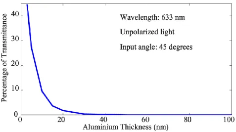
Figure 3.10 Reflection, absorption, and transmission of 10 nm aluminum on the glass substrate for the input angle of 45º and unpolarised light. ... 37
Figure 3.11 Percentage of transmitted power vs. thickness of aluminum, for 633nm, input angle of 45º and unpolarised light. ... 38
Figure 3.12 Reflection, absorption, and transmission of aluminum with the thickness of 100nm on the glass substrate for the input angle of 45º and unpolarised light. ... 38
Figure 3.13 Aluminum deposition. ... 39
Figure 3.15 UV exposure. ... 39
Figure 3.16 PR development. ... 40
Figure 3.17 Aluminum etching. ... 40
Figure 3.18 PR Removing. ... 40
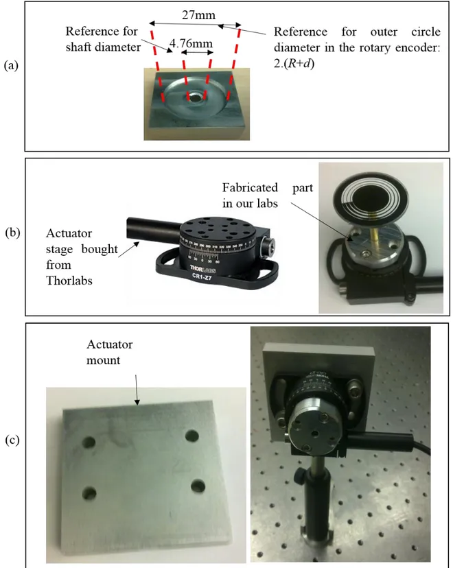
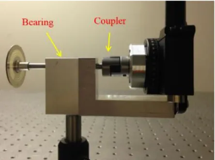
Figure 3.19 Primary mechanical setup, (a) Alignment part to find the center of rotary encoder while its installation on the shaft, (b) to install the rotary encoder on the motor stage bought from Thorlabs a mechanical piece was fabricated, and (c) installation of the actuator on the optical table. ... 41
Figure 3.20 Alignment device with two reference circles to get the center of the rotary encoder. 43 Figure 3.21 Increase the shaft area at its end. ... 43
Figure 3.22 Coupling the shaft to the actuator and its installation on the optical table. ... 44
Figure 3.23 Make a long path of 4.5 m using a series of mirrors. ... 45
Figure 3.24 Displacement of the reflected ray on the wall while rotating the rotary mask. ... 46
Figure 3.25 When a mirror rotates through an angle αº a beam of light reflected from it will rotate through an angle of 2αº. ... 46
Figure 3.26 Slot length calculation. ... 47
Figure 3.27 Fabricated rectangular slot (a) before and (b) after black painting and mounting. .... 48
Figure 3.28 Setup with HeNe laser. ... 48
Figure 3.29 (a) 3D view and (b) 2D view of slot coverage with the beam cross section. ... 49
Figure 3.30 Setup with laser diode and photodiodes. ... 50
Figure 3.31 (a) 3D view and (b) 2D view of slot coverage in the setup with a laser diode (diverging angles of 25º and 5º). ... 51 Figure 4.1 (a) Concept of the self-referencing rotation sensor showing the rotary encoder installed
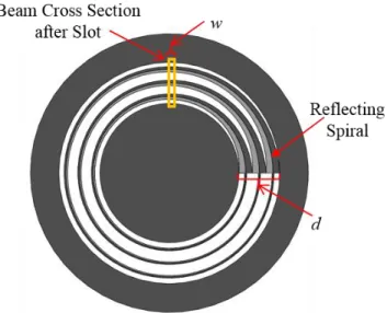
on a shaft. Light is incident on the rotary encoder at input angle of 45 degrees in which the “nominally” uniform distribution of light is reflected and the rest, transmitted, (b) The simplest form of a spiral rotary encoder: ring with the inner radius of R and width of d should
be divided into two areas of reflection and transmission according to the position, r(θ), which is a function of θ. Grey shows the reflection area. Axis x and y show coordinates used to calculate the transmitted and reflected powers at each angle in Eq. 4.6 and Eq. 4.7. Rectangle with width w and length 1.1d shows the light with a rectangular cross section on the rotary encoder. ... 53 Figure 4.2 Normalized reflected and transmitted powers and their ratio, in theory, supposing
uniform source light. ... 55 Figure 4.3 (a) Uniform, (b) Gaussian and (c) expanded Gaussian light distribution and (d) Ratio of
reflected and transmitted powers for uniform and expanded Gaussian sources vs. rotation angle, and error of expanded Gaussian source (in green dashed curve). ... 56 Figure 4.4 Rotary encoder called six-symmetric-patterned-rings as patterns of odd rings (light gray)
spirals are symmetric to the patterns of even rings (dark gray spirals). Light and dark gray show the reflection area and white area shows the transmission area. ... 57 Figure 4.5 Ratio of reflected and transmitted powers for different light distributions and the two
different patterns. ... 58 Figure 4.6 (a) Expanded Gaussian Source, (b) Shifted Expanded Gaussian Source, (c) Expanded
Gaussian Source with the second mode, and (d) Ratio of transmitted and reflected powers with the multi-patterned-rings design of Figure 4.4 and for Expanded Gaussian Source, Shifted Expanded Gaussian Source, and Expanded Gaussian Source with the second mode. ... 59 Figure 4.7 Fabricated rotary encoder of the designed pattern of Figure 4.4 ... 60 Figure 4.8 Percentage of ratio’s error vs. rotation angle for (a) “non-uniform source” defined as the
difference of ideal ratio and the ratio calculated in the condition of non-uniform source and six-symmetric-patterned-rings design, (b) “slot width” defined as the difference of ideal ratio and the ratio calculated in the condition that the ring’s pattern varying in the slot’s width, and (c) “non-uniform source and slot width” over the full range (0º-355º). ... 62 Figure 4.9 Whole setup to test the sensor. ... 65 Figure 4.10 (a) Transmitted power vs. rotation angle in theory and measurement, and relative error
relative error between them. (c) The ratio of transmitted and reflected powers vs. rotation angle in theory and experiment, and percentage of error in the full range (0º-180º). ... 67 Figure 4.11. The ratio of transmitted and reflected powers vs. rotation angle in theory and
experiment, and percentage of error in the full range (0º-180º) after error correction. Vibration error is one of the sources of error at 150 degrees which is a random error and uncorrectable as long as a faulty fixed power is added to the reflected power because of a slot with a length bigger than the width of the ring. Note that the sensor response is obtained from the division of transmitted power to the reflected power in which the error of reflected power, in the denominator, is more effective than the transmitted power, in the numerator, especially when the reflected power is low at high angles. ... 69 Figure 4.12 (a) Measured normalized transmitted and reflected powers without and with an
absorptive Neutral Density Filter (b) ratio of transmitted and reflected powers without and with Neutral Density Filter. Optical density, OD, of the filter is 0.3 which lets 50% of power to be transmitted. ... 70 Figure 4.13 (a) 60-degree pattern design with k=3 and (b) 120-degrees pattern design with k=2. 72 Figure 4.14 Linear displacement encoder. ... 73 Figure 4.15 multi-patterned-encoder for linear displacement sensor, K=1/3 for the operating range
of 15 mm. ... 74 Figure 5.1 the rotary encoder design with the one-ring pattern. ... 76 Figure 5.2 Normalized output powers (left axis), and the sensor response, ∆P/∑P, defined as per
Eq. 5.9 (right axis). ... 79 Figure 5.3 (a) Rotary encoder design with a six-ring pattern to solve the nonlinearity error coming
from the non-uniform source, (b) Opened multi-patterned-ring design in this paper, and (c) Opened multi-patterned-ring design in Chapter 4. ... 80 Figure 5.4 (a) Error of non-uniform source (expanded Gaussian source) vs. rotation angle for two
designs: one-ring pattern and six-ring pattern. (b) The error of non-uniform source for the six-ring pattern is zoomed. ... 82 Figure 5.5 Error of width of beam cross section vs. rotation angle. ... 84
Figure 5.6 Examination setup to test the ORS. An elliptically collimated beam is produced by means of two cylindrical lenses and passed through a slot. Reflecting/transmitting from/to OSR encoder, the light powers are captured and launched into PDs. ... 85 Figure 5.7 (a) Normalized output powers in the experiment (left axis) and ∆P/∑P vs. rotation angle
(right axis) and (b) calculated angle of rotation (left axis) and percentage of error (right axis) vs. rotation angle. ... 86 Figure 5.8 Normalized reflected and transmitted light powers (left-axis) and error (right-axis) in
the measurement of rotation angle vs. rotation angle from 355° to 360°. This shows that the error after 356.5° is very high which results in the limitation of range to 356.5°. ... 88 Figure 5.9 For different input powers on the rotary encoder: (a) Reflected and transmitted light
powers vs. rotation angle, (b) sensor response: ∆P/∑P and calculated angle of rotation vs. angle of rotation, and (c) full range error in percentage vs. rotation angle. ... 89 Figure 5.10 Full range error for (a) upward linear displacement, (b) downward linear displacement,
(c) upward angular displacement, and (d) downward angular displacement. ... 91 Figure 5.11 (a) 60-degree pattern design with K=1.8 and (b) 120-degrees pattern design with K=0.9. ... 95 Figure 5.12 Linear displacement encoder. ... 96 Figure 5.13 multi-patterned-encoder for linear displacement sensor, K1=0.13, for the operating
range of 15mm. ... 97 Figure 6.1 Replacing (a) traditional sensor with (b) smart sensor in FBW aircrafts. FCC: flight
control computer. ... 99 Figure 6.2 Block diagram of the rotary sensor system including mechanical, optical, and electrical
blocks which are included in the ultimate housing of sensor. LD: Laser diode, PD: Photodiode, USB: Universal serial bus, ADC: Analog to digital converter. ... 100 Figure 6.3 Mechanical assembly: mounts for LD, PDs, lenses in the reflection and transmission
sides, and shaft mount. The sizes of final housing are 80mm x 80mm x 50mm. LD: Laser diode, PD: Photodiode. ... 101 Figure 6.4 Optical setup, beam cross section on the rotary encoder is shown on the top. ... 102
Figure 6.5 Electrical module: PCB design in which photodiode circuits and microcontroller board are integrated (with the size of 65mm x 40mm). ... 105 Figure 6.6 (a) Signal processing procedure, (b) Moving average (MA) filter, and (c) Power
extraction (PE) in the reflection and transmission directions from the measured voltages. 107 Figure 6.7 (a) Beam cross section on the rotary encoder, (b) The patterned area on the rotary
encoder in which reflective and transmissive areas are shown in orange and gray, respectively, and (c) P0, P1 and P2 calculations. ... 108 Figure 6.8 (a) Test setup overview, (b) fabricated rotary encoder, and (c) Zoom of sensor prototype
including all mechanical, optical, and electrical module: 1- LD driver, 2- LD, 3- PCX (Source side) and slot, 4-Rotary encoder, 5- PCX and PD (Transmission side) 6- PCX and PD (Reflection side), 7- Detection circuits and microcontroller integrated in one PCB, 8- Shaft bearing, 9-Shaft, 10- Actuator driver USB, 11- PCB USB ... 111 Figure 6.9 (a) Measured voltages in transmission and reflection directions vs. time (b)-(c) zoomed
from 4.8 sec. to 5 sec. and (d)-(g) the voltage signals before and after MA filter for a different length of MA filter window. ... 113 Figure 6.10 (a) normalized transmission and reflection powers in theory and experiment, (b) sensor
response, ratio of transmission and reflection powers in theory and experiment, (c) full range error in percentage without MA filter, and (d) full range error in percentage with MA filter. Note: The sensor response is equal to θ, hence is scaled to . ... 114 Figure 6.11 (a) Measured voltages in transmission and reflection directions vs. time and rotation
angle, (b) sensor response, and (c) full range error for two cases of with and without optical density (OD) filter. ... 116 Figure 7.1 Anodized aluminum. ... 121 Figure 7.2 Absorption of metal-dielectric multilayer filter which is more than 99.7% at the
operating wavelength. The thickness of absorptive layer causes 0.01% error over the full range. ... 121 Figure 7.3 Rotary encoder fabrication structure with the details of absorptive, reflective, and
Figure 7.4 Top-view of the rotary encoder with absorptive, transitive, and reflective filters. ... 123 Figure A.1 : Comparison of migration of telecommunication and aerospace industries from
mechanical systems to electrical systems and finally to optical systems ... 132 Figure A.2: All-optical aircraft including a fiber optic backbone network and monitoring systems. FCC: Fight Control Computer, Fiber Bragg Grating ... 134 Figure A.3: Migration from (a) FBW-FCS to (b) FBL-FCS ... 135
LIST OF SYMBOLS AND ABBREVIATIONS
AC Alternating currentADC Analog to digital converter AFCS Automatic flight control system
AM Amplitude Modulation
AOI Angle of incidence AR Anti-reflection
COTS Components off the shelf EMI Electro-Magnetic Interference FBL Fly-by-light
FBW Fly-by-wire
FCC Flight control computer FCS Flight control system
HF High frequency
ISS Integrated sensor system LAN Local area network
LD Laser diode
LED Light emitting diode LPF Low pass filter
LVDT Linear variable displacement transducers MAGFET Magnetic field effect transistor
MEMS Microelectromechanical systems MOA Minute of Angle
MTBF Mean time between failures
OD Optical density
OPAMP Operational amplifier ORS Optical rotary sensor PCB Prototype circuit board PCX Plano-concave
PD Photodiode
PM Permanent magnet
PR Photo-resist
RC Resistance-capacitor RMS Root mean square RPM Revolution per minute
RVDT Rotary variable displacement transducers SNR Signal to noise ratio
TIA Trans-impedance amplifier USB Universal serial bus
UV Ultra-violet
CHAPTER 1
INTRODUCTION
1.1 Project overview
This research started in September 2012 in collaboration with a research and development project, AVIO402, related to the technological development plan of industrial partners, Thales Canada Inc., and Bombardier Aerospace Inc., for next generation avionic systems. For the first year, this project was funded by AVIO402. For the next two years, from September 2013 to August 2014, it was funded by the NSERC-CREATE training program in integrated sensor systems (ISS).
This project is in the design and fabrication of optical sensors for avionic applications especially for pilot input control applications, in particular, rotation and translation sensing in fly-by-wire (FWB) flight control systems (FCS). FCSs are operated based on position sensors for detecting pilot controls, actuator displacements, and flight control surfaces movement. The sensors currently used in FCS are fully analog Rotary/Linear Variable Differential Transducer (R/LVDT) working on electromagnetic principles. Therefore, it is expected that the optical equivalent smart position sensors will be used to connect to high-performance standard digital avionics data buses to get rid of heavy electrical wiring cables between sensors and the flight control computer (FCC). In responding to these technological challenges, this project aimed to develop lightweight and high-reliability optical displacement sensors to replace the current position sensors to provide enhanced performance while reducing the cost of deployment and maintenance. Therefore, smart sensor requirements for avionic systems have been considered in the research presented here.
In the following section, a short introduction to FCS will be presented in order to know where the rotation sensors are used in this system.
1.2 Introduction to FCS
FCS is responsible for control of actuators in flight control surfaces [1] such as rudders and elevators in the tail and ailerons in the wings of aircraft. Movement of certain flight control surfaces results in changing of aerodynamic force and consequently alteration of aircraft’s attitude in relation to three axes: yaw, roll, and pitch [1]. Aircraft axes are shown in Figure 1.1 and explained as follows:
Roll axis is for turning around the longitudinal axis. Yaw axis is for turning right and left.
Pitch axis is for taking off and landing.
Figure 1.1 Three axes of an airplane1.
To manipulate three axes of aircraft, different flight control surfaces should be displaced in the right position. Ailerons, rudders, and elevator, shown in Figure 1.2, should be controlled to adjust
roll, yaw, and pitch axes, respectively.
Conventional FCS applies hydraulic actuators and control valves by cables that pass the length of the airframe [2]. The disadvantage of this hydraulic cable-controlled system is the weight of long cables which result in a heavy aircraft. However, FBW airplanes apply electronic displacement sensors in which the analog signals from the sensor are sent to the FCC interface. Hence, analog signals are processed in FCC interface which consumes lots of pins on connectors and board surface [3]. The solution to this challenge is a smart sensor in which the corresponding electronics for demodulation and digitizing processes of analog signals should be removed from FCC and
packed with the sensor itself in a compact housing [3]–[5]. Conventional FCS, FBW FCS, and fly-by-light FCS are explained in the following sections.
Figure 1.2 Primary flight control surfaces2.
1.2.1 Conventional FCS
Early airplanes - such as Boing 727 in the early 60’s and Boeing 737 in 1967 [6] - used mechanical FCS [7] shown in Figure 1.3. In a conventional FCS, the pilot command in the cockpit inceptors (such as rudder pedals, spoiler handle, flap handle, etc.) is transferred through a mechanical transmission system of cables and pulleys to the actuators which influence flight control surfaces in the wing or tail of the aircraft. Heavy cables and pulleys pass along the aircraft from cockpit in the nose of the airplane to the actuator in the tail or wing resulting in a heavy load and non-integrated FCS.
Figure 1.3 Conventional FCS in which cables and pulleys are used to transfer captain command in the airplane nose to actuators in flight control surfaces.
An example of conventional FCS for elevator control using cables and pulleys is shown in Figure 1.4.
Figure 1.4 Conventional FCS of cables and pulleys3.
1.2.2 FBW FCS
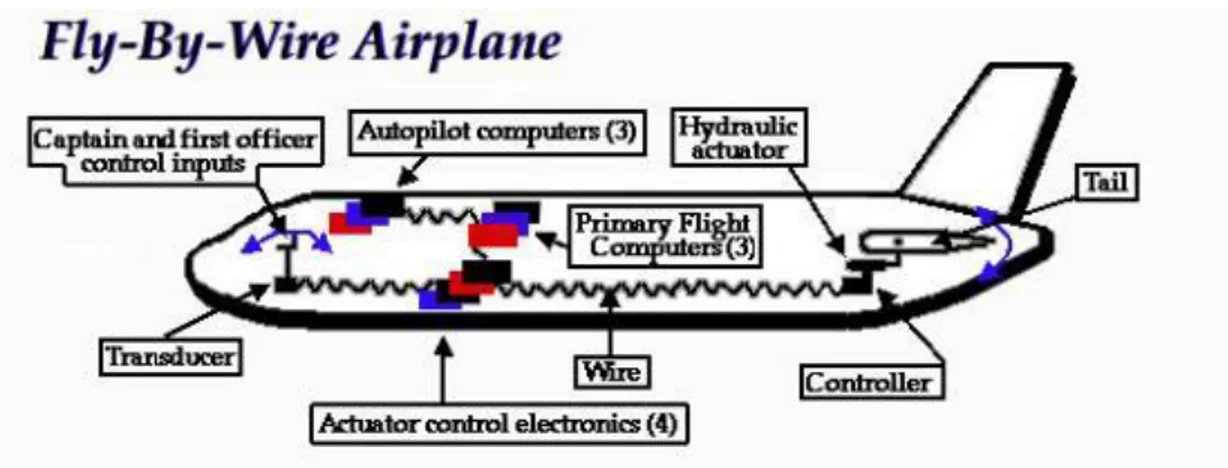
The FBW-FCS was proposed as an evolutionary step for FCS. A well-known example of an aircraft with FBW-FCS is the Boeing 777 delivered to United Airlines in 1995 [6]. Another example is the Airbus A320 which made its first flight in 1987 [1]. Other examples are the Airbus A330, A340, A380, and the Boeing 787 [8]. In FBW-FCS, the mechanical control system is replaced by the electronic control system to reduce the aircraft weight and integrate the systems. Hence, displacement sensors were required to convert mechanical signals (Pilot commands) to the electrical signals which have to be sent to the FCC. The processed signals from FCC are sent to the actuators in flight control surfaces and automatic flight control system (AFCS) [9].
It is worth noting that in comparison to conventional FCS, FBW system uses wires to send/receive data between cockpit, FCC, and actuators in flight control surfaces resulting in impressive weight reduction and integrated system [2]. Another major benefit of FBW-FCS is the ability to tailor the system’s characteristics at each point in the airplane [1].
An example of FBW-FCS is shown in Figure 1.5 to clarify how a command in the cockpit is transferred to the elevator in the tail of airplane to adjust pitch angle while taking off or landing.
The captain command (mechanical signal by displacing elevator handle) is converted to the electrical signal through a transducer which sent to FCC-interface for demodulation and digitization. The digitized signal is sent to FCC for processing. The processed signal is sent to actuator electronics and then to the elevator actuator in the flight control surface.
Position sensors are used in this system for one of the following applications:
1. Pilot input controls: the position of cockpit inceptors such as such as sidesticks, conventional columns-wheels, rudder pedals, spoiler handle, and flap handle, etc.
2. Actuator displacements near to flight control surfaces 3. Flight control surfaces movement
Figure 1.5 an example of FBW-FCS to adjust elevator position4.
1.3 Motivation
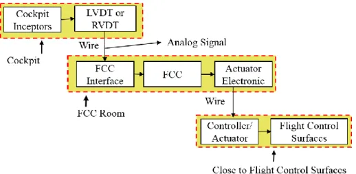
Block diagram of FBW-FCS is shown in Figure 1.6 in which captain command is converted to an electrical signal through a displacement sensor, rotary/linear variable differential transformer (RVDT/LVDT). The analog signal is sent to FCC interface for demodulation and digitization and thus, the produced digital signal is sent to FCC. The processed command from FCC is sent to actuator electronics and consequently to the actuators moving flight control surfaces. This block
diagram clearly shows that the signals between cockpit, FCC, and flight control surfaces are communicated by wires.
Figure 1.6 block diagram of FBW-FCS. FCC: flight control computer, LVDT: linear variable differential transformer.
Smart sensor concept: In the next step of flight control evolution, it is desired to receive condition of FCS over a digital link in FCC. Thus, the analog sensor and its related electronics should be packed in a single housing. As shown in Figure 1.7, the output of the smart sensor is sent directly to FCC via a bus and thus there is no need to FCC interface.
Figure 1.7 Smart sensor in FCS.
In an FBW system, there are 29 RVDT/LVDT in the cockpit, in one example, and each has usually 5 wires resulting in the total number of 145 wires as reported in [3]. However, the outputs of smart sensors are sent to FCC via only 4 buses [3] in a control system with smart sensors. Smart sensor system not only results in reducing the weight but also integrating the FCS.
Based on the request of industry parties and with the enormous advances made in the field of photonics, we are going to use a simple analog coding encoder system to implement angular position sensing with low weight, low cost, high reliability and resolution in the avionic system.
1.4 Contributions in this Thesis
New analog optical rotation sensors have been designed, fabricated, and tested for avionic applications. Following contributions have been made:
Two different NEW rotation encoders have been designed to propose various operating ranges and sensitivities as these two parameters are in a trade-off with each other. In the first one, the sensitivity is higher while in the second one the operating range is broader.
The first one which is based on the ratio of reflected and transmitted powers has a high sensitivity.
The second one has a broader operating range but lower sensitivity, the sensor response is obtained from the ratio of subtraction to summation of reflected and transmitted powers.
The sensors are SIMPLE: In order to propose a simple sensor, the number of components is minimized and they are selected from the available components in the market. In addition, the design of rotary encoder and consequently its fabrication are not complicated. These simplifying approaches are explained as follows:
ONLY one laser diode and two photodiodes are used for the source and detection, respectively.
The optical setup is designed to use components off the shelf (COTS) and there is no need to design special lenses which result in increased cost.
The design of the rotary encoder is simple in comparison to the optical digital rotary encoders on the market (details in Section 2.6). As a consequence, fabrication procedure is not complicated and the accuracy of microfabrication technology is enough to meet the final accuracy requirements of avionic applications.
The sensor is RELIABLE: To deliver reliable sensors for avionic applications, they should be self-referencing and self-calibrating. Hence, the pattern of rotary encoders are designed to meet these requirements as explained as follows:
Self-referencing: the sensor response is obtained from the ratio of two powers (or the ratio of subtraction to the summation of two powers). Hence, the effect of source fluctuation and aging is canceled in the ratiometric sensor response. In addition, having two photodiodes with the same silicon material, two powers at the detection side are aged approximately equal and cancel each other’s effect in the ratio-metric sensor response.
Self-calibrating: Multi-patterned-rings design has been used to overcome the problem of the non-uniform source. All optical sources are non-uniform by their nature. Moreover, high order modes could appear by aging. Using multi-patterned-ring design, one can assume the source is uniform in each subring.
The sensors are SMART: In order to propose a smart sensor, all parts of the sensor including optical and electrical components and the rotary encoder mask on the shaft have been packed into a single housing and the digitized signals are sent to the computer via a bus. Applying smart sensor in an aircraft results in wire removal between sensor and FCC and replacing it with Buses and removal of related electronics in the FCC interface for digitization and demodulation of the analog signal. These two improvements result in:
Low maintenance: cable management between sensor and FCC would be easier and with the lower cost because of replacing more than 100 wires with 4 buses.
Low EMI: buses are less sensitive to EMI in comparison to wires
Low weight: With a lighter aircraft, the rate of fuel consumption is decreased which is followed by an increase in the range, the distance an aircraft can fly between takeoff and landing. Another effect of lower weight could mean more cargo or passenger handling.
Small footprint: more space will be available by replacing of wires with buses and removal of electronics related to sensors in the FCC interface.
The sensors consume LOW POWER: the power consumption on the source side and detection side are verified as follows:
The power consumption of the source to drive the laser diode is 40mA×9V=360mW. The power consumption in the detection side in photodiode detection circuits is 16mW.
As the total optical power is 1mW, the maximum photocurrent produced by a silicon photodiode is 0.5mA. The voltage to drive the op-amps is -16V to +16V. Hence, the total power consumption on the analog detection side is 16mW. In the digital part, the voltage and current on the board are 3.3V and 0.5mA resulting in a power consumption of 1.7mW.
The total power requirement is less than 0.5 watt including the power on the detection side, analog and digital.
1.5 Research objectives
It is expected to design optical sensors which measure the rotation angle and works linearly. It should be fabricated from a piece of glass which is light and cheap. Moreover, for producing the beam, an optical setup including LD should be used which is an incoherent and inexpensive source. In addition, an optoelectronic circuit should be designed and fabricated to convert the light into voltage. So at the end, we hope to design and make an optical sensor which has a lot of benefits over current electronic sensors.
1. Literature review in optics, optical sensors, and optical rotation sensors
In this section, a literature survey of optical elements such as a laser, LD, and PD is required. In addition, taking courses of fundamentals of photonics and optical engineering is needed. Moreover, it is indispensable to be familiar with principles of sensing and classification of optical sensors. (It is done, could be improved)
2. Making a proper beam using lenses and LED: In this section, it is necessary to be familiar with choosing and ordering proper elements such as lenses, mounts, and LDs.
Getting practical knowledge about characterizing, mounting, and making a proper beam should be obtained. (It is done, could be improved)
3. Design, simulation, and fabrication of mask for rotation sensor: In this section, the design of the encoder masks based on the principles of sensing should be done. Using software such and Matlab and Solidworks for simulation and drawing the encoder mask is needed. Finally, it is required to fabricate them. (one sample is designed and fabricated) 4. Design, simulation and making detecting electronic circuits: In this part, design and
simulation of the electronic circuit are required to convert the optical signal to the electronic signal such as voltage and current. In the next step, the electronic circuit should be implemented.
5. Testing: In this section, after implementing the optical and electronic parts, the whole setup of the optical sensor should be tested. (first fabricated sample is tested which shows the design works but it should be re-fabricated to resolve some problems)
6. Making a housing: In this section, housing for the optical elements such as lenses and LD should be designed and fabricated. (Solidworks should be applied and student is familiar with it now)
7. Deliverables: In this part, the results of design and fabrications are published as conference and journal papers. It was also necessary to deliver reports to the industrial partners by the end of each phase. Moreover, at the end of the Ph.D. journey, the dissertation should be written.
1.6 Thesis outline
The remainder of this thesis is structured as follows: In Chapter 2, a literature review of different rotation sensors and their characteristics will be presented with a specific emphasis on current optical rotary sensors (ORSs) in the market and rotary sensors currently used in the avionic application. In Chapter 3, rotary encoder design principles are presented as well as its drawing and fabrication procedure. This Chapter also includes optical and mechanical setups and test approaches. In Chapter 4 and 5, analog optical rotary encoders with the operating range of 0º to 180º and 0º to 356.5º will be presented, respectively. In Chapter 6, the prototyping procedure of smart sensor will be presented. Finally, in Chapter 7, one can find the conclusion and future works.
CHAPTER 2
LITERATURE REVIEW: ROTATION SENSORS
Rotary sensors are key components in several systems, such as motion capture devices [10]–[11], industrial control application to monitor rotation of mechanical parts [10], [12]–[14], and automotive sensors for tracking steering-angle [10], [15], [16]. Rotary displacement sensors are widely employed in FBW aircraft and avionics systems for flight control purposes [2], [3], [17], [18].A variety of technologies and approaches can be applied to measure rotary displacement [13], [19]. Magnetic rotation sensors, potentiometers, resolvers/synchros, MEMS-based rotation sensors, and Gyro-based rotation sensors are briefly explained in the following sections followed by their advantages and disadvantages. In addition, two important categories of rotation sensors are verified, optical rotation sensors in the current market and rotary variable displacement transducers (RVDTs) currently used in FBW avionic applications. Finally, all sensors and compared with each other and their potential for avionic application are discussed.
2.1 Magnetic rotation sensors
2.1.1 Working principle
The rotation angle is encoded into the magnetic flux in magnetic rotation sensors such as magneto-resistive, Hall Effect, and magnetic encoders [13]. As a magnetic flux is a vector quantity, magnetic sensors may measure the total magnitude (ex: Hall Effect devices) or angle direction of a magnetic field (ex: magneto-resistive devices).
Figure 2.1. Magnetic sensor. PM: Permanent magnet, MR: Magneto-resistive, I: electric current. In these sensors, rotation angle modulated into the magnetic flux is converted to the electrical signal by means of Hall elements [16] or magnetic resistance (MR) as shown in Figure 2.1. Hall Element
is a thin sheet of conductive material with connections perpendicular to the direction of current flow and MR device has a resistance changing with the applied magnetic field.
The principle of working of magnetic rotation sensors is displayed in the format of the block diagram in Figure 2.2.
Figure 2.2. The principle of working (Magnetic rotation sensors).
2.1.2 Pros and Cons
Magnetic sensors could be used in hot and dirty environments and they are known for their infinitesimal resolution, and robust and solid construction [20]–[22]. In addition, they are very rugged, suitable for small-lot production [15], high-speed operation (100kHz) [23]
However, external electromagnetic interference (EMI) can seriously affect the sensor response due to intrinsic operation of magnetic sensors having a high sensitivity to magnetic flux [13]. In addition, the output of a magnetic sensor requires some signal processing (ex: linearization) to translate the sensor output into the desired parameter value.
2.2 Resistive rotation sensors
2.2.1 Working principle
Potentiometer or pots are the common terms used for resistive displacement sensors [13]. By rotating the shaft of a potentiometer, the length and consequently the resistance of the internal resistor is increased resulting in the modulation of rotation angle into the resistance (Figure 2.3). Working principle of resistive rotation sensors is displayed in the format of the block diagram in Figure 2.4.
Figure 2.4. The principle of working (Resistive rotation sensors).
2.2.2 Pros and Cons
Potentiometers are low-cost, simple, and EMI resistant.
However, they suffer from the eventual wear-out due to the sliding contact wiper with the resistive material [19].
2.3 Resolver and synchro
2.3.1 Working principle
Resolver and synchro are shown in Figure 2.5. In synchro, a primary coil (in the rotor) is excited by an AC signal. Electric signals are inducted into the secondary coils which have the angle 120º with each other with the rotation of the rotor. In resolvers, two secondary coils have the angle of 90º with each other.
Resolvers and synchros have the same principles as RVDTs with the only difference that the transfer coils are fixed in RVDT. Unlike RVDTs, they are multi-turn with the full operating range [19].
Working principle of resolvers/synchros is displayed in the format of the block diagram in Figure 2.6.
Figure 2.6. The principle of working (Resolvers/synchros).
2.3.2 Pros and Cons
Resolvers/synchros are very robust and have the capability of working in dirty environments. However, the need for an AC signal source is the weak point of these sensors [24].
2.4 Rotation sensor based on MEMS
2.4.1 Working principle
Various approaches could be taken to measure rotation angle by MEMS such as capacitive, piezoelectric, piezo-resistive, magnetic, and optical categories [25]. However, the capacitive MEMS are the most spread ones. MEMS devices do not measure the angle directly. In reality, MEMS accelerometers and gyroscope MEMS are used for measurement of rotary displacement The accelerometer MEMS used in iPhone measure the projection of the gravity vector on the sensitive axis as shown in Figure 2.7. The angle of rotation, 𝛼, is calculated as Eq. 2.1
arcsin( / )
Figure 2.7 MEMS accelerometer for rotation angle measurement. Vector A shows the projection of the gravity vector on the sensitive axis.
where g is acceleration due to gravity and vector A is the projection of gravity vector on the sensing axis. Hence, these types of MEMS are practical in the devices with negligible acceleration in comparison to the gravity. For example, it could be used in iPhone but cannot be used in the airplanes which have acceleration while landing and taking off. In the case of using an accelerometer for angle measurement, the gravitational components should be extracted from the total acceleration components. Hence, an information measurement unit (IMU) should be used containing certain sensors such as inertial sensors [26].
Figure 2.8 MEMS Gyroscope: mass suspended by use of four springs, 𝑘𝑥/𝑦 𝑎𝑛𝑑 𝑐𝑥/𝑦 are spring constants and damping factors, respectively [27].
Another MEMS development could be applied for angle measurement is MEMS Gyroscope [27], [28]. In this approach, as shown in Figure 2.8, the angle of free vibration of a mass suspending by
elastic members is measured. When sensor experiences an external angular velocity, the angular velocity is modulated into vibrating positions (x and y) of suspending mass. Hence, by demodulating of positions, the angular velocity is obtained. Angular displacement is attained by integration of angular velocity over the time in which the error in each time will be accumulated resulting in a high error.
Working principle of MEMS is displayed in the format of the block diagram in Figure 2.9.
Figure 2.9. The principle of working (MEMS).
2.4.2 Pros and Cons
MEMS have a small size in the range of µm with the final package in the range of mm. Nonetheless, this positive makes these kinds of sensors incompatible for avionic applications.
However, it is not standardized yet. In addition, fabrication procedure is time-consuming [29]. Moreover, small imperfection has a huge impact on the performance of these sensors [27].
2.5 Rotation sensor based on Gyro
2.5.1 Working principle
Gyroscopes work based on inertia law stating an object at rest stays at rest and an object in motion stays in motion. Hence, when the spinning part of gyroscope spins at high speed, it tends to keep the direction of its axis. There are three types of gyroscopes: spinning mass, optical, and vibratory [30]. Spinning mass gyroscopes have a mass spinning continually. Optical gyroscopes [31] works based on Sagnac effect stating phase shift between two waves counter-propagating in a rotating ring interferometer is proportional to the loop angular velocity. Vibrating gyros are based on Coriolis effect that induces a coupling between two resonant modes of a mechanical resonator [30]. Gyros measure angular velocity. The angular velocity could be integrated over the time to find the rotation displacement. Consequently, small errors in each time will be accumulated and resulted in a big error in the angle measurement [27], [32].
Working principle of Gyros is displayed in the format of the block diagram in Figure 2.10.
Figure 2.10. The principle of working (Gyro).
2.5.2 Pros and Cons
Gyros are excellent devices for angular velocity measurement.
However, error accumulation for rotary displacement measurement and being bulky and expensive are disadvantages of Gyros [26]
2.6 Optical rotation sensors
Optical sensors include a variety of devices, all of which use light as the means to transform displacement into electrical signals [13]. They have attracted a lot of attention in biomedical sensing [33], [34], structural monitoring [35], gas sensing [36], [37], humidity sensing [38], mining [39], renewable energies to assess quality of biodiesel [40], bio/chemical sensing [33], [41] and avionic [42]–[44]. Optical sensors not only are accurate, light and small but also have high speeds and high resolution [16], [45]. However, optical sensors are susceptible to dirty environment and lose performance at higher temperatures (greater than 70°C) because of the intrinsic properties of the photodiodes and laser diodes commonly used as receivers. Moreover, the fine target structures of high-resolution optical sensors can be easily affected by mechanical shock and vibration. Different types of optical rotation encoder sensors in terms of the principle of working and the scheme are explained in the following sections.
2.6.1 Different types of optical rotation sensors (Working principle)
Optical rotary encoder sensors found in the literature to date are mainly digital [10], [12], [46]– [49] which work just based on the reflected or transmitted power. Working principle of optical rotation sensors is displayed in the format of the block diagram in Figure 2.11.
Figure 2.11. The principle of working (Optical rotation sensors).
2.6.2 Different types of optical rotation sensors (Schemes)
Two schemes can be applied to the rotary encoder [49], incremental and absolute.
In the incremental encoder, the displacement is detected relative to a reference point [13]. Consequently, some form of the reference signal in needed in order to define a reference position. The current position thus is decremented/incremented as appropriate [13]. Figure 2.12 shows incremental rotary encoder [50].
Figure 2.12: Incremental rotary encoder [50].
Figure 2.13 shows absolute rotary encoder [50] in which the position of the disk is detected absolutely from a set of binary signals [13]. It is a very complicated method and consequently, it is difficult to make a high accuracy disk [49].
Figure 2.13 Absolute rotary encoder [50].
2.6.3 Pros and Cons
There are many advantages for optical rotary encoder sensors. They are small and light [16] with high speed and high resolution (even 0.001º).
However, the encoder design is complex [45]. They contain numerous parts such as several light sources [51]. In the detection side, an array of photodiodes or an image sensor is used; therefore, to decode the measurand from the measured signals, complex signal processing should be done in the detected scheme [12]. Certain systems include image sensors [10], [52], [53] in which the properties of the image sensor and image processing system are needed to decode the response of sensor from the coded information. In addition, they work solely on transmitted light [54], reflected light [51], [52], or diffracted light [14] making the sensor susceptible to source power fluctuation. Moreover, preliminary calibration and self-calibration circuits are used to solve the problem of nonlinearity coming from the non-uniform light source and power reduction of the source which makes the sensor complex. All of these characteristics make these kinds of sensors very expensive and inappropriate for small-lot production [15].
2.7 RVDT
2.7.1 Working principle
Electromagnetic induction is the basic principle of RVDTs. As shown in Figure 2.14, a primary coil is excited with a carrier signal and movement of the ferromagnetic core within the flux path results in a change of second coils reluctance. Consequently, the rotation angle is modulated into the differential amplitude of the secondary coils [13]. RVDTs currently used in FBW-FCS [3].
Figure 2.14 RVDT, AC: Alternating current.
Working principle of RVDTs is displayed in the format of the block diagram in Figure 2.15.
Figure 2.15. The principle of working (RVDTs).
2.7.2 Pros and Cons
RVDTs work based on ratiometric sensor response resulting in a high reliability. In addition, they are compact [13] and the infinitesimal resolution and robust and solid construction are possible with these kinds of sensors [20]–[22].
However, a typical linear range of measurement of RVDT is about -40º to +40º with a nonlinearity error of about 1% [13], [20]; to increase the range, the sensor response is no longer linear [55]. Moreover, external EMI can seriously affect the sensor response as the intrinsic operation of inductive sensors has a high sensitivity to magnetic flux [13]. In addition, they are packaged as traditional sensors (analog sensors not smart sensors) and currently used in FBW-FCS. These
sensors used in cockpit inceptors produce analog signal sent to FCC interface. Management of nearly 30 RVDTs (each with 5 wires) in the cockpit is one challenge. Another challenge is consuming lots of connector and board surface of FCC interface. Hence, it is aimed to replace the analog sensor with a smart sensor to produce a digital signal over buses [3].
2.8 Comparison of various rotation sensors
Being resistance to EMI/ EMI source, resolution/accuracy, single-turn/multi-turn, contact/non-contact are summarized in Table 2.1.
In addition, temperature range, operating range, analog/digital and operational speed of different rotation sensors are summarized in Table 2.2.
Price, size/weight, and applications and manufacturers of various rotation sensors are summarized in Table 2.3 and Table 2.4, respectively.
Table 2.1: Rotary position sensors: resistance to/source of EMI, Accuracy, Single-turn/Multi-turn, and contact/non-contact. EMI resistance/ Source of EMI Resolution/ Accuracy Single-turn (ST) Multi-turn (MT) Contact(C) non-contact (NC) Descriptions
Magnetic Sensitive 12 bits [56] - NC
MOA: Minute of angle Resistive Highly resistive 1% over the full range [57] ST/
MT C
Resolver/Synchro Resistive [24] 5 to 0.5 MOA [19] MT NC
MEMS
ACC
Source of EMI [58] - - NC/C
Gyro
Gyro decreasing with time NC
Optical encoder Not sensitive 17 bits [15] ST/
MT NC
Table 2.2: Rotary position sensors: temperature range, operating range, and Analog/digital.
Temperature range Operating Range
Analog (A) Digital (D)
Operation Speed
High speed (>100kHz) Descriptions
Magnetic -40 ºC to +85 ºC [56] 360º [56] A/D High speed [23]
MOA: Minute of angle Resistive -55ºC to 300ºC [56] Less than 360º
in ST A Low speed
Resolver/Synchro -55ºC to 70ºC [57] 360º A Low speed
MEMS
ACC
0º to 45º [27] A/D -
Gyro -40ºC to 85ºC [59]
Gyro 360º A
Optical encoder -40 ºC to 70 ºC - D High speed [15]
Table 2.3: Rotation displacement sensor: Price, and size/weight.
Price Size/Weight Descriptions
Magnetic Low [60] - ST: Single turn TI: Texas Instrument Resistive Low [60] - Resolver /Synchro High 58mm-80mm [61]
MEMS Low: MEMS used in iPhone 4 cost $2.60, supplied by STMicroelectronics [62]
In µm range [29] Packages in mm [59]
Gyro High [26], [27] -
Optical
sensor Varies[60] 58mm to 116 mm for ST [56]
RVDT High[60]
Table 2.4: Rotation displacement sensor: applications and manufacturers.
Applications Manufacturers Descriptions
Magnetic Automation equipment and robotics [16], [22] BEI
Motion Sensors Inc.
ST: Single turn TI: Texas Instrument
Resistive Avionic [57] Wearable Sensors [11] BEI Honeywell Resolver /Synchro
High-temperature applications such as aircraft
engines, petrochemical refining [13] Honeywell Baumer Machine-tool and robotics [19]
MEMS Apple products, Bosch, TI, STMicroelectronics,
InvenSense Gyro Altitude determination (Pitch/roll/yaw angle
measurement) in aircraft navigation system -
Optical sensor
Automotive manufacturing [10], robotics, motion capture system
BEI, Gurley, Heidenhain, Canon, Lucas Ledex
TR Electronix Hewlett Packard
RVDT Avionic [3]
Honeywell Motion Sensors Inc.
CHAPTER 3
DESIGN AND METHODOLOGY
3.1 Introduction
This chapter outlines the rotary encoder design and the research methodology within following sections: rotary encoder design, pattern drawing, fabrication procedure, and testing methods.
3.2 Rotary encoder design
3.2.1 Hypothesis
The main concept of the rotation sensor is shown in Figure 3.1. On the source side, a collimated beam with an elliptical cross-section is needed to illuminate a rectangular slot to make a good use of the optical power. Light is launched at a 45º angle of incidence (AOI) onto the rotary encoder after passing through the slot in which partially reflected and the rest is transmitted. On the detection sides, reflection and transmission, two convex lenses (PCX) collect the light onto the photo-detectors.
Figure 3.1 Rotation sensor concept.
Figure 3.2 shows a series of transformations needed to convert rotation angle to the electrical signals in our sensor. Firstly, the rotation angle is encoded into two areas of reflection and transmission by means of a rotary encoder. Reflection and transmission areas are encoded into reflection and transmission light powers, respectively, by applying a light source which is supposed to be uniform. Finally, light powers are converted to electrical signals through detectors.