DOCTORAT DE L’UNIVERSIT´
E F´
ED´
ERALE
TOULOUSE MIDI-PYR´
EN´
EES
D´elivr´e par :
l’Universit´e Toulouse 3 Paul Sabatier (UT3 Paul Sabatier)
Pr´esent´ee et soutenue le 21/02/2019 par :
Lola MASSON
SAFETY MONITORING FOR AUTONOMOUS SYSTEMS: INTERACTIVE ELICITATION OF SAFETY RULES
JURY
Simon COLLART-DUTILLEUL RD, IFSTTAR, France President of the Jury
Elena TROUBITSYNA Ass. Prof., KTH, Sweden Reviewer
Charles PECHEUR Prof., UCL, Belgium Reviewer
Jean-Paul BLANQUART Eng., Airbus D&S, France Member of the Jury
H´el`ene WAESELYNCK RD, LAAS-CNRS, France Supervisor
J´er´emie GUIOCHET MCF HDR, LAAS-CNRS, France Supervisor
´
Ecole doctorale et sp´ecialit´e : EDSYS : Informatique 4200018 Unit´e de Recherche :
for them. Our work focuses on autonomous systems, and the company Sterela provided us with a very interesting case study, the robot 4mob. I thank Augustin Desfosses and Marc Laval, from Sterela, who welcomed me in their offices and worked with us on this robot. In 2017, I was lucky enough to spend three months at KTH, Sweden, in the Mechatronics division. I thank Martin T¨orngren, who welcomed me in the lab, and with whom I appreciated meeting while walking in the forest around the campus. I also want to thank Sofia Cassel and Lars Svensson, with whom I had very enjoyable work sessions, as well as all the other PhD students and post-docs who made my stay a great both work and personal experience. I thank Elena Troubitsyna, from KTH, Sweden, and Charles Pecheur, from UCLouvain, Belgium, for reviewing this thesis. I also thank to Simon Collart-Dutilleul, from IFSTTAR, France, for presiding on my thesis jury.
Of course, I don’t forget J´er´emie Guiochet and H´el`ene Waeselynck, from LAAS-CNRS, who supervised this work and accompanied me through the good times as well as the hard ones. Thanks also to Jean-Paul Blanquart from Airbus Defense and Space and to Kalou Cabrera, post-doc at LAAS at the time, for participating in the meetings and for their precious help and advice.
The work days of the last three years would have been different if I were not among the PhD students and post-docs of the TSF team. Thanks to those I shared an office with, providing much-needed support on the hard days and sharing laughs on the good ones. Thank to all for the never-ending card games. Special thanks to Jonathan and Christophe for the memorable nights debating, and for their open-mindness. To all, it was a pleasure hanging out and sharing ideas and thoughts with you.
Thanks to the one who is by my side every day, for his support in every circumstance. Thanks to my crew who has always been there, to my family and to all those who make me laugh and grow.
itoring 17
1.1 Concepts and Techniques for Safe Autonomous Systems . . . 18
1.1.1 Fault Prevention . . . 18 1.1.2 Fault Removal . . . 20 1.1.3 Fault Forecasting . . . 22 1.1.4 Fault Tolerance . . . 24 1.2 Monitoring Techniques . . . 26 1.2.1 Runtime Verification . . . 27
1.2.2 Reactive Monitors for Autonomous Systems . . . 29
1.3 SMOF: Concepts and Tooling . . . 32
1.3.1 SMOF Process Overview . . . 32
1.3.2 SMOF Concepts and Baseline . . . 33
1.3.3 Safety and Permissiveness Properties . . . 34
1.3.4 SMOF Tooling . . . 34
1.4 Conclusion . . . 35
2 Feedback from the Application of SMOF on Case Studies 37 2.1 Sterela Case Study . . . 38
2.1.1 System Overview . . . 38
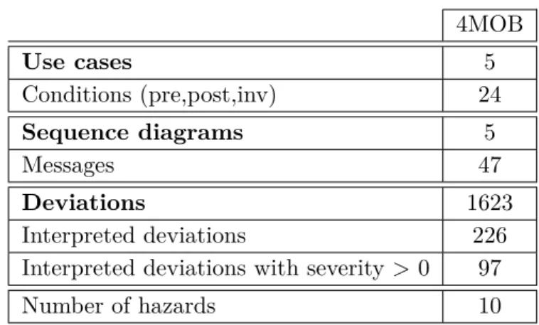
2.1.2 Hazop-UML Analysis . . . 39
2.1.3 Modeling and Synthesis of Strategies for SI1, SI2 and SI3 . . . 44
2.1.4 Modeling and Synthesis of Strategies for SI4 . . . 51
2.1.5 Rules Consistency . . . 59
2.2 Feedback from Kuka Case Study . . . 61
2.2.1 System Overview . . . 61
2.2.2 SII: Arm Extension with Moving Platform . . . 61
2.2.3 SIII: Tilted Gripped Box . . . 64
2.3 Lessons Learned . . . 65
2.3.1 Encountered Problems . . . 65
2.3.2 Implemented Solutions . . . 68
2.4 Conclusion . . . 69
3 Identified Problems and Overview of the Contributions 71 3.1 Modeling of the Identified Problems . . . 72
3.1.1 Invariant and Strategy Models . . . 72
3.1.3 Identified Problems . . . 73
3.2 Manual Solutions to the Identified Problems . . . 74
3.2.1 Change the Observations . . . 75
3.2.2 Change the Interventions . . . 75
3.2.3 Change the Safety Requirements . . . 76
3.2.4 Change the Permissiveness Requirements . . . 76
3.3 High Level View of the Contributions . . . 77
3.3.1 Diagnosis . . . 77
3.3.2 Tuning the Permissiveness . . . 78
3.3.3 Suggestion of Interventions . . . 80
3.4 Extension of SMOF Process and Modularity . . . 81
3.4.1 Typical Process . . . 81
3.4.2 Flexibility . . . 83
3.5 Conclusion . . . 83
4 Diagnosing the Permissiveness Deficiencies of a Strategy 85 4.1 Preliminaries - Readability of the Strategies . . . 86
4.1.1 Initial Display of the Strategies . . . 86
4.1.2 Simplifications with z3 . . . 87
4.2 Concepts and Definitions . . . 88
4.2.1 Strategies and Permissiveness Properties . . . 88
4.2.2 Problem: Safe & No perm. . . 89
4.2.3 Permissiveness Deficiencies of a Strategy . . . 91
4.3 Diagnosis Algorithm and Implementation . . . 93
4.3.1 Algorithm . . . 94
4.3.2 Simplification of the Diagnosis Results . . . 97
4.3.3 Implementation . . . 100
4.4 Application to Examples . . . 101
4.4.1 SII: The Arm Must Not Be Extended When The Platform Moves At A Speed Higher Than speedmax. . . 101
4.4.2 SI4: The Robot Must Not Collide With An Obstacle. . . 102
4.5 Conclusion . . . 104
5 Tuning the Permissiveness 105 5.1 Defining Custom Permissiveness Properties . . . 106
5.1.1 From Generic to Custom Permissiveness . . . 106
5.1.2 A Formal Model for the Functionalities . . . 107
5.1.3 Binding Together Invariants and Permissiveness . . . 108
5.2 Restricting Functionalities . . . 110
5.2.1 Diagnosing the Permissiveness Deficiencies with the Custom Prop-erties . . . 110
5.2.2 Weakening the Permissiveness Property . . . 111
5.2.3 Automatic Generation and Restriction of Permissiveness Properties 112 5.3 Application on Examples . . . 113
6 Suggestion of Candidate Safety Interventions 121
6.1 Preconditions and Effects of Interventions . . . 121
6.2 Identifying Candidate Interventions . . . 123
6.2.1 Magical Interventions . . . 123
6.2.2 Generalize the Interventions Effects . . . 125
6.2.3 Interactive Review of the Interventions . . . 126
6.3 Algorithm . . . 128 6.4 Application to an Example . . . 133 6.5 Conclusion . . . 136 Conclusion 137 Contributions . . . 137 Limitations . . . 138 Perspectives . . . 139
1.4 SMOF process . . . 32
1.5 System state space from the perspective of the monitor . . . 33
2.1 Sterela robot measuring runway lamps . . . 39
2.2 HAZOP-UML overview . . . 39
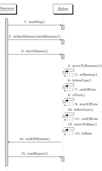
2.3 UML Sequence Diagram for a light measurement mission . . . 41
2.4 Behavior for the invariant SI1. . . 46
2.5 SI3 the robot must not enter a prohibited zone . . . 49
2.6 Expected strategy for SI3 . . . 50
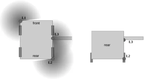
2.7 Disposition of the lasers on the robot . . . 52
2.8 Visual representation of the classes of (x,y)coordinates . . . 53
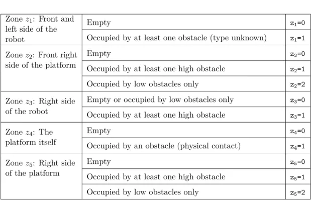
2.9 Obstacle occupation zones around the robot . . . 56
2.10 Declaration of the zones variables and their dependencies . . . 58
2.11 Merging partitions into a global variable . . . 60
2.12 Manipulator robot from Kuka . . . 61
2.13 Strategy for the invariant SII with the braking intervention only . . . 62
2.14 Strategy for the invariant SII with the two interventions . . . 63
2.15 Positions of the gripper and corresponding discrete values . . . 64
3.1 Identified problems, proposed solutions . . . 74
3.2 High level view of the diagnosis module . . . 78
3.3 High level view of the tuning of the permissiveness properties . . . 79
3.4 High level view of the suggestion of interventions . . . 80
3.5 High level view of the SMOF V2 process . . . 82
3.6 View of the contributions . . . 82
4.1 Definitions of safe and permissive strategy (repeated from Chapter 3) . . 89
4.2 Definition of the Safe & No perm. problem (repeated from Chapter 3) . . 89
4.3 Strategy for the invariant SIIwith the braking intervention only (repeated from Figure 2.13) . . . 90
4.4 Principle of diagnosing the permissiveness deficiencies and impact of a strategy. . . 92
4.5 Process for use of the diagnosis and simplification algorithms . . . 94
4.6 Permissiveness deficiencies for SI3 . . . 96
4.7 PI(w1, f ull stop) . . . . 97
4.8 PI(w2, f ull stop) . . . . 97
4.10 Non-existing paths for the invariant SI3 . . . 101
4.11 Safe and non-permissive strategy for the invariant SII(repeated from Fig-ure 2.13) . . . 102
4.12 Diagnosis for the non-permissive strategy for SII . . . 102
4.13 Obstacle occupation zones around the robot (repeated from Figure 2.9) . 102 5.1 Required reachability for generic permissiveness . . . 106
5.2 Required reachability for custom permissiveness . . . 106
5.3 Invariant and functionalities models . . . 107
5.4 Binding of the functionalities model and the invariant model . . . 109
5.5 Binding for two velocity variable . . . 109
5.6 Weakening generic and custom permissiveness . . . 111
5.7 Template for the functionalities model . . . 113
5.8 Partitioning of thesg variable . . . 115
5.9 Single strategy synthesized for the invariant SII with generic permissive-ness properties (repeated from Figure 2.14) . . . 116
5.10 Additional strategy synthesized for the invariant SIIwith the custom per-missiveness properties. . . 116
5.11 Safe strategy synthesized for the invariant SI3 . . . 118
6.1 Non-permissive strategy synthesized for SII(repeated from 2.13) . . . 123
6.2 Strategy synthesized for SII with magical interventions . . . 124
6.3 Strategies synthesized fore SII with the candidate interventions . . . 128
2.4 Partitioning and abstraction of the variables for the Cartesian model . . . 53
2.5 Partitioning of zone variables for the full case model . . . 57
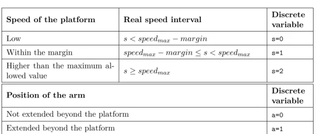
2.6 Partitioning of the variables s and a . . . . 62
2.7 Summary of the points of interest highlighted by the two case studies. . . 66
5.1 Partitioning of the variables sinv and ainv (repeated from Table 2.6) . . . . 114
5.2 Partitioning of the variables sfct and afct. . . 114
6.1 Identification of candidate interventions from the magical interventions for SII . . . 124
6.2 Setting static precondition and generalizing the effects of the interventions for SII . . . 125
6.3 Resulting candidate interventions for SII . . . 126
6.4 Algorithms 6 and 7 applied to the gripper invariant . . . 134
him to sustain a minor injury. The toddler had previously fallen on the ground and the robot was not able to detect him [Knightscope, 2016]. In 2017 in Washington D.C., the same model of this robot was patrolling office buildings when it tumbled down a flight of stairs and landed in a fountain, unintentionally destroying itself [Knightscope, 2017]. These two examples illustrate the variety of accidents that can be caused by autonomous systems. As autonomous systems become part of more application domains, from pub-lic security to agriculture, the care sector, or transportation, the number of accidents increases. Autonomous systems can cause damage to themselves and their physical en-vironment, resulting in financial losses, but, more importantly, they can injure humans (sometimes fatally, as in the accident involving the Tesla autonomous car [NTBS, 2016]). Ensuring safety of autonomous systems is a complex task, and has been the subject of much research in the last decades. Fault tolerance is a part of the safety domain, and is concerned with guaranteeing a safe execution despite the occurrence of faults or adverse situations. A technique that can be used for this purpose is to attach an active safety monitor to the system. A safety monitor is a mechanism that is responsible for keeping the system in a safe state, should hazardous situations occur. It can evaluate the state of the system through observation, and influence its behavior with interventions. The monitor follows a set of safety rules.
Defining the safety rules for monitors is arduous, particularly in the context of au-tonomous systems. As they evolve in dynamic and unstructured environments, the sources of hazard are various and complex, and a large number of rules is necessary to tolerate these hazards. At the same time, autonomous systems typically must make progress towards completing some set of tasks. The monitor needs to preserve the au-tonomy of the system, while ensuring that no dangerous state is reached.
Before this thesis, the Safety MOnitoring Framework (SMOF) has been developed at LAAS to solve this problem. It encompasses a synthesis algorithm to automatically synthesize safety rules, which prevent unsafe behaviors (safety properties) while still permitting useful ones (permissiveness properties). SMOF has been successfully applied to several case studies, but has limitations in some cases. Sometimes the synthesis cannot return a satisfying set of safety rules. When this happens, it is hard to identify why the synthesis failed, or how to construct a satisfying solution. Often, the problem stems from the failure to satisfy the permissiveness requirements: safety can be obtained only at the expense of conservative restrictions on behavior, making the system useless for its purposes.
In this thesis, we propose an interactive method for the elicitation of safety rules in case SMOF’s synthesis fails to return a satisfying solution. To assist the user in
these cases, three new features are introduced and developed. The first one addresses the diagnosis of why the rules fail to fulfill a permissiveness requirement. The second one allows the tuning of the permissiveness requirements based on a set of essential functionalities to maintain. The third one suggests candidate safety interventions to inject into the synthesis process.
In Chapter 1, we present the context of this work. We give a high level view of the different means for ensuring the safety of autonomous systems, before focusing on the definition of safety monitors. We also explain the main concepts of SMOF.
Chapter 2 presents the results of applying SMOF to a new case study—a maintenance robot from the company Sterela. We also revisit the results of a previous case study involving a manufacturing robot from the company KUKA. In light of these two case studies, we discuss the main limitations of SMOF and the manual solutions that were implemented for them. We deduce tracks for improvements, and identify the needs for our contributions.
In Chapter 3, we come back to the problem identified in Chapter 2 where no satis-fying solution can be synthesized and discuss it in detail. From there, we present our contributions, and how they fit together for solving this issue.
Chapters 4, 5 and 6 present the detail of our contributions. In Chapter 4, we detail a diagnosis tool that can help the user identify why the synthesis failed to return a satisfying solution. In Chapter 5, we define a template for better adapting the synthesis to the system’s expected tasks. Finally, in Chapter 6, we present an interactive method for defining new interventions.
We conclude with a summary of the contributions and present some perspectives and thoughts for future work.
List of publications:
• Lars Svensson, Lola Masson, Naveen Mohan, Erik Ward, Anna Pernestal Brenden, et al.. Safe Stop Trajectory Planning for Highly Automated Vehicles: An Optimal Control Problem Formulation. 2018 IEEE Intelligent Vehicles Symposium (IV), Changshu, China, Jun. 2018.
• Mathilde Machin, J´er´emie Guiochet, H´el`ene Waeselynck, Jean-Paul Blanquart, Matthieu Roy, Lola Masson. SMOF - A Safety MOnitoring Framework for Au-tonomous Systems. In IEEE Transactions on Systems, Man, and Cybernetics: Systems, vol. 48, no 5, pp. 702-715, May 2018. IEEE.
• Lola Masson, J´er´emie Guiochet, H´el`ene Waeselynck, Kalou Cabrera, Sofia Cassel, Martin T¨orngren. Tuning permissiveness of active safety monitors for autonomous systems. In Proceedings of the NASA Formal Methods, Newport News, United States, Apr. 2018.
• Lola Masson, J´er´emie Guiochet, H´el`ene Waeselynck, Augustin Desfosses, Marc Laval. Synthesis of safety rules for active monitoring: application to an airport
Contents
1.1 Concepts and Techniques for Safe Autonomous Systems . . . 18
1.1.1 Fault Prevention . . . 18 1.1.2 Fault Removal . . . 20 1.1.3 Fault Forecasting . . . 22 1.1.4 Fault Tolerance . . . 24 1.2 Monitoring Techniques . . . . 26 1.2.1 Runtime Verification . . . 27
1.2.2 Reactive Monitors for Autonomous Systems . . . 29
1.3 SMOF: Concepts and Tooling . . . . 32
1.3.1 SMOF Process Overview . . . 32
1.3.2 SMOF Concepts and Baseline . . . 33
1.3.3 Safety and Permissiveness Properties . . . 34
1.3.4 SMOF Tooling . . . 34
1.4 Conclusion . . . . 35
Autonomous systems bring new challenges to the field of dependability. They have complex non-deterministic decision mechanisms, evolve in unstructured environments, and may be brought to interact with humans or other systems to carry out their tasks. They are thus subject to new types of faults. The classical dependability techniques need to be adapted to encompass these new constraints. This chapter starts by presenting a high-level view of the state of the art on the dependability means, applied to autonomous systems (Section 1.1). It then gradually focuses the discussion on the safety monitoring approach—SMOF—that we use and extend in our work.
In Section 1.1, active safety monitors are introduced in relation to one of the depend-ability means, namely fault tolerance. Such monitors are responsible for ensuring safety of the system despite its faults: they observe the operation of the system, and are able to trigger corrective actions to prevent hazardous situations from occurring, according to some safety rules. Section 1.1 discusses how monitors can be introduced at various
architectural levels to serve different purposes. They can also be separated from the control architecture, to act as the ultimate barrier against catastrophic failures.
Section 1.2 provides more details on active monitoring, with an emphasis on the core techniques. Two broad classes of techniques are identified, coming from distinct commu-nities. The property enforcement mechanisms from the runtime verification community manipulate traces of events to ensure their correct sequencing and timing. In contrast, the reactive monitors from the safety-critical control system community have a focus on state invariants: the values of variables are monitored and actions are taken to keep these values inside a safety envelope.
Section 1.3 provides an overview of SMOF, the safety monitoring framework devel-oped at LAAS. This framework targets reactive monitors that are independent from the control architecture. SMOF has been conceived to solve the problem of safety rules spec-ification in the context of autonomous systems. It provides a synthesis algorithm based on model-checking, to synthesize safety rules from a model of the available observations and actions, along with the safety invariants to hold. The invariants are extracted from a hazard analysis.
Section 1.4 concludes the discussion.
1.1
Concepts and Techniques for Safe Autonomous
Sys-tems
[Avizienis et al., 2004] propose four means to classify techniques for ensuring depend-ability of systems:
Fault prevention: preventing the occurrence or introduction of faults, through rigor-ous engineering methods, and the use of dedicated tools (Section 1.1.1);
Fault removal: reducing the number and severity of the faults, using verification techniques (Section 1.1.2);
Fault forecasting: estimating the number of faults and their consequences, mostly using risk analysis methods (Section 1.1.3);
Fault tolerance: avoiding service failure despite the presence of faults remaining after the use of the previous methods, or introduced during the operational life of the system (Section 1.1.4).
1.1.1 Fault Prevention
Fault prevention aims at preventing the occurrence or introduction of faults in a sys-tem and is part of general engineering techniques for syssys-tem development. Autonomous systems are very complex and the diversity of their tasks forces developers to deal with heterogeneous components when developing their software. In [Blanquart et al., 2004], the authors draw recommendations for the design of dependable autonomous systems:
sion making into several levels, each one using a different level of abstraction. Classically, the hierarchical architecture is divided in three layers:
• The decisional layer uses an abstract representation of the system and its en-vironment to compute plans to achieve some objectives. These objectives can be sent to the system by another system or a human operator. This layer does not guarantee a real time execution.
• The executive layer converts plans computed by the decisional layer into se-quences of tasks that will be performed by the functional layer. This layer is sometimes merged with one of the other layers.
• The functional layer executes the tasks. This layer is responsible for command-ing the actuators, retrievcommand-ing the sensors’ data, computcommand-ing trajectories, etc. It is often composed of components that can interact but do not have a global view of the system. Each layer sends the results of the different tasks’ executions, and some potential errors that could not be handled, to the higher level. Some hybrid versions of the hierar-chical architecture exist, making direct communications available between the functional and decisional layer, or combining layers together.
The recommendations for standardized components, architectures and interfaces [Blanquart et al., 2004, Bruyninckx et al., 2013] can be addressed by the use of middle-ware like ROS [Quigley et al., 2009], OROCOS [Bruyninckx, 2001], and by component-based frameworks like GenoM [Mallet et al., 2010] or Mauve [Lesire et al., 2012]. The component-based frameworks can also provide code generation facilities, thereby re-ducing the probability of introre-ducing development faults. In some cases, these frame-works are also linked to formal methods (mathematically-based techniques used to specify, develop or verify software systems). GenoM automatically synthesize for-mal models that can be used for checking temporal properties (with FIACRE/Tina [Fiacre, 2018, Tina, 2018, Foughali et al., 2018], or with BIP [Basu et al., 2006]). Mauve provides facilities for analyzing execution traces.
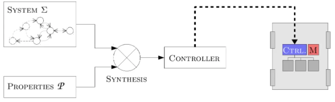
Controller synthesis: Supervisory control synthesis (SCT) [Ramadge and Wonham, 1987] also contributes to fault prevention. It is a tech-nique that aims at automatically generating a suitable controller for a software system. From a model of the system as an automaton, and a set of properties to satisfy, a synthesis mechanism is used to generate the controller (see Figure 1.1). The controller restricts the capabilities of the system, by triggering controllable events, according to the specified properties. In [Shoaei et al., 2010], a controller is synthesized for manufac-turing robots in a shared environment. The authors propose to generate non-collision properties from simulation and formal models of the robots operations, and to integrate these in the synthesis, resulting in collision-free manufacturing units. [Lopes et al., 2016]
Figure 1.1: Concept of supervisory control synthesis
successfully apply controller synthesis for swarm robotics — large groups of robots interacting with each other to collectively perform tasks. In [Ames et al., 2015], the authors use controller synthesis for a walking robot. The synthesized controller shows improved performance compared to the manually-implemented controller initially used. Robotics seems to be a promising application field for controller synthesis.
1.1.2 Fault Removal
Fault removal aims at removing faults from the considered system. It can occur during the development phase, where faults are found and corrective actions taken before de-ployment of the system; or during its use, where faults that have occurred are removed (corrective maintenance) and actions are taken to avoid the occurrence of new faults (predictive maintenance). In this section, we will focus mainly on the fault removal techniques that can be used during the development phase. Removing faults from a system is done in three steps. The verification step checks that the system conforms to some properties. If the verification reveals a property violation, the diagnosis step identifies what fault led to the the property violation and the correction step brings the necessary changes to the system to remove the fault. If the diagnosis and correc-tion steps are very dependent on the considered system, the verificacorrec-tion techniques are more generic — we will detail the most common ones in the following. The verification techniques can be classified into two categories: static verification, which does not need to execute the system, and dynamic verification which does. Autonomous systems are more challenging to verify than classical control systems [Pecheur, 2000]. A full model of the system is usually not available or is hard to build, the number of scenarios to be analyzed is infinite, and the software is non-deterministic (mostly due to concurrency). However, formal methods are widely used with success for the verification of autonomous systems, and the user can refer to the extensive survey in [Luckcuck et al., 2018] for more references.
Static verification aims at mathematically proving that a program complies with some requirements. It guarantees that all executions are correct according to the
con-(LTL)— defining the allowed behaviors of the robots are manually translated (and later on automatically translated by their tool CRutoN [Gainer et al., 2017]) into suitable inputs for a model checker. The model checker then checks for satisfiability of some properties (priority between rules, interruptibility). Stochastic model-checking is an ex-tension of model-checking to deal with uncertainties that are inherent to autonomous systems [Kwiatkowska et al., 2007]. It evaluates the probability that a property is sat-isfied within a scope. Examples of such approaches for autonomous robots can be found in [O’Brien et al., 2014] or [Pathak et al., 2013].
Verifying the decision algorithms used in the decisional layer is challenging. In [Fisher et al., 2013], model-checking is used to verify all the possible decisions made by the decision mechanism of autonomous systems. The authors can then ensure that the system will never intentionally make the decision to move towards an unsafe situation. However, an unsafe situation could still occur, for instance due to an unexpected change in the environment (it is impossible to have a complete model of the environment).
In [Desai et al., 2017], the authors propose to use model-checking combined with runtime monitors. For the model-checking of the robot software, one has to make as-sumptions about the low-level controller and the environment. The addition of an on-line monitor allows one to check that these assumptions hold at runtime. A similar approach is explored in [Aniculaesei et al., 2016], where the model checker UPPAAL is used at design time to verify that no collision can occur. A monitor is used at runtime to verify whether the conditions used for the model checking still hold.
The exhaustive aspect of model checking makes the approach appealing, but it has some limitations. Complex systems can have extremely large (infinite) state spaces, mak-ing them hard to completely explore (state explosion issue). Also, the modelmak-ing step is very error-prone, and it is hard to obtain a model that is both accurate enough to repre-sent the system and abstract enough to limit the state explosion. A deep understanding of both the application-to-verify and the model-checker used is needed.
In theorem proving, a formal proof of the correctness of a system is produced, through logical inferences. In [T¨aubig et al., 2012], an obstacle avoidance algorithm for static ob-stacles is proved correct, using the theorem prover Isabelle. This process produced a robust argumentation that allowed the authors to get a SIL3 of IEC 61505 certification for the presented method and implementation. In [Huber et al., 2017], the authors for-malize traffic rules for vehicle overtaking. They use the help of the Isabelle prover to achieve a high level trustworthiness of the formalization. Though theorem proving is an efficient verification technique, it has not been extensively investigated in the field of robotic systems. The tools are generally difficult to master and require a higher expertise compared to other approaches.
Dynamic verification consists in executing the system or a model of the system in a specific context in order to analyze its behavior. A set of inputs (called a test case) is given to the system. For symbolic inputs, we talk about symbolic execution. For valued inputs, we talk about test. The outputs are then analyzed, and a pass/fail verdict is emitted by a procedure called the test oracle. Defining the test oracle for autonomous systems is not trivial: they are nondeterministic and their tasks are complex and vari-ous. To overcome this issue, [Hor´anyi et al., 2013] propose to automatically generate test cases from UML scenarios: the traces are evaluated against the requirements expressed by the scenarios. Injecting faults is another way to define test cases, and is explored in [Powell et al., 2012] for autonomous systems. For testing autonomous systems on a mission level, field testing is used. This is expensive and potentially dangerous — as testing robots in a real environment can damage the robot or its environment; and only provides a limited coverage —as only a limited number of situations can be tested in a limited time. For these reasons, the development of simulators is a major improvement. However, the result of tests in simulation are valid only assuming that the simulation is representative of the real behavior. Several simulation environments exist and the reader can refer to [Cook et al., 2014] for a comparison. Drone collision-avoidance is tested in simulation in [Zou et al., 2014]. Evolutionary search is used to generate chal-lenging test cases, and proves to be efficient in identifying remaining hazards. Gen-erating the simulated environment is challenging. The environment needs to closely represent the world in which the robot will evolve once deployed. However, as shown in [Sotiropoulos et al., 2017], it is possible to identify software bugs in simulation in a simpler environment than the one into which the robot will be introduced. The same au-thors study the difficulty of the generated map in [Sotiropoulos et al., 2016], and how to make it vary by tuning parameters like obstruction and smoothness. Randomness can be introduced in the generation of the simulated world, as in [Alexander and Arnold, 2013] where the authors test the control software of a robot on situations as varied as possible. In [Abdessalem et al., 2018], evolutionary algorithms are used to guide the generation of scenarios to test for autonomous vehicles.
1.1.3 Fault Forecasting
The idea of fault forecasting is to evaluate what faults may occur and what would be their consequences. It is mainly done by performing risk analyses that “system-atic[ally] use [the] available information to identify hazards and to estimate the risk” [ISO/IEC Guide 51, 2014]. The risk is evaluated using qualitative levels such as “low” or “high”. Different risk analysis techniques can be applied at different stages of the development, to different components and abstraction levels.
The risk analysis techniques are classified into two categories: bottom-up, that analyze the effect of faults for known deviations (e.g., Failure Modes Effects and Criticality Analysis (FMECA), Hazard Operability (HAZOP)) or top-down, that identify which faults lead to an undesired event (e.g., Fault Tree Analysis (FTA)). These methods are commonly used for autonomous systems [Dhillon and Fashandi, 1997], but they are facing some challenges. Due to the complexity and non-determinism of the decision
The HAZOP technique associates a guide word like “more” or “late” to each element of the analyzed system, to help the user identify hazards associated with these devia-tions. It has been used on a therapeutic robot for children in [B¨ohm and Gruber, 2010] where the system is decomposed into components and functions to be thoroughly an-alyzed. A variant dedicated to software called HAZOP-SHARD (Software Hazard Analysis and Resolution in Design) is used in association with a specific list of en-vironmental risks in the context of autonomous systems [Woodman et al., 2012]. In [Troubitsyna and Vistbakka, 2018], HAZOP is combined with the analyses of data flows to identify safety and security requirements. These requirements are then formalized in Event-B to analyze the dependencies between the architectures’ components and the safety and security mechanisms. In [Guiochet, 2016], the HAZOP technique is adapted to the analysis of UML diagrams. The user systematically analyzes all the components of the diagrams with the help of guide words. This method is one of the few focusing on human-robot interaction.
Also focusing explicitly on human-robot interaction, SAFER-HRC is a
semi-automatic risk analysis for Human Robot Collaboration (HRC) applications
[Askarpour et al., 2016]. A team of experts builds a model of the studied system and the possible human-robot interactions, and identifies what hazards may occur from the list presented in [ISO 12100, 2013]. This model is then analyzed to identify— knowing the dynamics of the systems— what interaction accidents may occur; some corrective actions can then be taken. [Stringfellow et al., 2010] introduce the STPA (Systems The-oretic Process Analysis) method that considers a model of the potential faults leading to accidents. From it, they identify which erroneous control commands could lead to an ac-cident. This method has been applied to a medical robot in [Alemzadeh et al., 2015]. In the method ESHA (Environmental Survey Hazard Analysis) [Dogramadzi et al., 2014], new guide words are used to analyze the interactions with the environment. They specif-ically take into account unexpected interactions (not planned on in the mission), as they are the ones causing the most damage, as the authors claim. Several methods can also be used in combination. In [Alexander et al., 2009], Energy Trace and Barrier Analy-sis (ETBA) is used as a preliminary analyAnaly-sis. In this method, the release of energy is analyzed— an accident occurs when an unexpected or excessive amount of energy is released. The Functional Failure Analysis (FFA) method is also used, as well as HA-ZOP. The results of these hazard analyses are then used in an FTA to identify their causes. Though these methods are not exhaustive, they are systematic and cover a large amount of hazards. Among the identified faults, some cannot be removed: they have to be tolerated.
Figure 1.2: Monitors in a hierarchical architecture
1.1.4 Fault Tolerance
Fault tolerance aims at providing a correct service despite the occurrence of faults. This is essential, as no complex system can be considered fault-free. This is particularly true of autonomous systems, which include complex decisional functions and may face adverse and unspecified situations. To mitigate hazards during the operational life of the system, some mechanical (a specific shape, a soft cover, etc) or hardware (bumpers, etc) ways exist but we will not detail them here and only consider software mechanisms. Fault tolerance is achieved in two steps: fault detection and recovery. This implies that the mechanism has ways to observe faulty behaviors and ways to trigger corrective actions. Several approaches for fault tolerance exist. For instance, redundant sensors can detect inconsistent values, or a backup software component can be used if the primary one crashes. Another approach is to design a specific component that can be either integrated into the architecture or independent of it, and this is what we will be interested in. We will refer to this component as a monitor. A monitor is only responsible for safety: it checks whether some properties are violated or not, and potentially triggers relevant corrective actions. Some monitors are designed specifically to tolerate the fault of one or several layers in a hierarchical architecture (see Section 1.1.1). They interact with a single layer, as represented in Figure 1.2.
In the functional layer, the monitor is mostly responsible for sensors and actuators errors. In [Crestani et al., 2015] a monitor is attached to each hardware and software component of the functional layer. Similarly, in [Zaman et al., 2013], such monitors are integrated in a ROS architecture. These monitors are able to detect errors such as sensor defects or timeout issues. They are very similar to classical fault tolerance approaches such as redundancy or watchdogs.
to make decisions in order to avoid collisions for trucks following each other (platooning). The component selects the safe state to evolve towards, and triggers a safety action to reach it. In [Py and Ingrand, 2004], the monitor is integrated between the functional layer and the decisional layer, replacing the traditional executive layer. It can block erroneous requests from the decisional layer and interrupt the execution of functions. The same approach with different technologies is explored in [Bensalem et al., 2009], where a monitor is automatically synthesized, following an idea close to controller synthesis. [Huang et al., 2014] propose a single component called RVMaster, integrated in ROS, that supervises the others, verifying some safety properties. Even though this component is not strictly speaking integrated in a hierarchical architecture, it can be assimilated into an executive layer as it is supervising the execution of the functional components.
In the decisional layer, the monitor usually checks that the plan satisfies some safety constraints or that the planner isn’t faulty. In [Ertle et al., 2010], a model of the environmental hazards learned prior to deployment and updated on-line is used to evaluate the generated plan with regard to safety principles. In [Gspandl et al., 2012] the decisional layer is able to tolerate faults from the functional layer by comparing the current state to a correct state. Considering faults of the planners themselves, [Lussier et al., 2007] proposes to tolerate them using redundant diversified planners. Similarly, [Ing-Ray Chen, 1997] proposes to tolerate intrinsic planning faults (failure of the planning algorithm) using a parallel architecture.
Multi-layer mechanisms: [Gribov and Voos, 2014] propose a multi-layer architec-ture, that associates to every hazard a software component treating them. This ap-proach is useful as it can be integrated into any existing ROS architecture, and helps ensuring safety when off-the-shelf components are used. However, the safety mechanisms are spread at different levels, which is a disadvantage as it does not allow the treatment of safety of the system as a whole. In [Vistbakka et al., 2018], a multi-layered approach is used for the safe navigation of a swarm of drones. A high level decision center is in charge of the safe navigation of the drones among known hazards. It can change the swarm configuration or generate new routes for the drones. Additionally, at a low level, each drone has its own local collision avoidance mechanism, that computes “reflex movements” to avoid or mitigate collisions with unforeseen obstacles.
Independent monitors: Another approach for monitoring safe behavior of an au-tonomous system is to design an independent component that is separated from the control channel. This idea is represented by the large gray box in Figure 1.2. This component needs to be independent so that potential errors in the main control channel do not propagate to it. It also needs specific ways to observe the system’s state and
to intervenes should a deviation be perceived. This type of component is also referred to in the literature as a safety bag [Klein, 1991], safety manager [Pace et al., 2000], au-tonomous safety system [Roderick et al., 2004], guardian agent [Fox and Das, 2000], or emergency layer [Haddadin et al., 2011]. In [Tomatis et al., 2003], an autonomous tour-guide was successfully deployed for five months using, among other safety mechanisms, an independent monitor that is implemented on its own hardware component. It only has limited means of observation and intervention, but will not be affected by any fault of the main software part. In [Woodman et al., 2012], a monitor is able to filter com-mands to actuators or stop the robot in case of a safety rule violation. The monitor also intervenes if it detects a strong uncertainty in the observations. It is not independent from the controller in terms of observation means: they both share the same view of the system state, therefore potentially the same errors. In [Casimiro et al., 2014], the authors propose to implement a safety kernel on a dedicated hardware board. The safety kernel detects the violation of a set of safety rules defined in design time. It detects the operational context (e.g., sensor defect) and can adjust accordingly the level of service of the appropriate functions. For instance, if the distance sensor is faulty, the safety kernel can adjust the safety distances margin to ensure that no collision can occur. In [Machin et al., 2018], a safety monitor implemented independently detects when a warn-ing threshold is crossed, and can trigger appropriate safety interventions to prevent the system from evolving towards a hazardous state.
As can be seen, monitors play useful roles at the various layers of the architec-ture. Generally speaking, the monitoring integrated into the control channel offers more powerful detection and recovery mechanisms than an independent monitor. The latter category of monitor has more limited observation and intervention means, but can act as the ultimate barrier against faults when all other mechanisms fail in their protection role. It is typically kept simpler and assigned a high integrity level. In the next section, we discuss the existing monitoring techniques and key options underlying the design of monitors for autonomous systems.
1.2
Monitoring Techniques
Monitoring involves some verification at runtime to detect a potentially dangerous be-havior. This verification concern allows for potential cross-fertilization between fault tolerance and fault removal techniques. Indeed, runtime verification (RV) has emerged as a fruitful field of research in recent years, with close relationships with model checking and testing. We first describe the main concepts of RV, the similarities and differences compared to the other verification techniques, and comment on the type of monitors considered by the RV community (Section 1.2.1). We then discuss other types of mon-itors considered for autonomous systems, which accommodate a more reactive view (Section 1.2.2).
Figure 1.3: Typical process of runtime verification (adapted from [Falcone et al., 2013])
1.2.1 Runtime Verification
We synthesize here the views of [Leucker and Schallhart, 2009], [Falcone et al., 2012], [Falcone et al., 2013] and [Delgado et al., 2004] that the reader may refer to for further information. [Falcone et al., 2013] defines Runtime Verification as “a dynamic analy-sis method aiming at checking whether a run of the system under scrutiny satisfies a given correctness property”. The idea is to check a set of properties against a system’s execution.
Typically, the RV framework is described as in Figure 1.3.
First, a monitor is generated from a property, typically specified with an automata-based or logic-automata-based formalism. This step is referred to as monitor synthesis. The monitor is a decision procedure for a property. It observes the execution of the system through events, and generates a verdict on the satisfaction of the property. The verdict produced by the monitor could be two-valued (the property is satisfied or not), but can also have additional values allowing a finer evaluation of the property. The verdict generated can be accompanied with a feedback, which gives additional information to the system, for instance in order to trigger corrective actions. Classically, recovery is referred to as runtime enforcement. The runtime enforcement mechanism detects (in anticipation) the violation of a property. It can then delay or block some events, to avoid the violation. The authors of [Ligatti et al., 2009] propose to formalize and analyze the types of properties that can be enforced by a runtime monitor.
Second, the system is instrumented to be able to generate the appropriate events. This step is highly dependent on the system itself and the technologies used.
Third, the system is executed and its traces analyzed. The analysis can occur during the system execution (online monitoring), or after the execution if the events have been stored (offline monitoring). When the monitor in included in the system’s code itself,
it is called inline. This is conceptually very close to the monitors integrated in the architecture presented in Section 1.1.4. When the monitor is its own entity, it is called
outline. This is similar to the independent monitors presented in Section 1.1.4.
RV receives growing attention in the field of autonomous systems (see [Luckcuck et al., 2018, Pettersson, 2005]). For instance, in [Lotz et al., 2011], RV is used for monitoring robotics components, both during the development process for debugging, as well as at runtime for fault and error detection and handling. An interesting aspect is that direct code instrumentation is seldom desirable for autonomous systems. The source code of such systems may not be available, and the modification of the code may affect timing and correctness properties — which can also invalidate a former certifi-cation, resulting in non-negligible additional costs. [Kane et al., 2015] propose to build a passive RV monitor that gets the appropriate events from passive observation of the communication buses. They successfully apply this approach to an autonomous research vehicle. Similarly, in [Pike et al., 2012] the authors propose to delegate fault tolerance to a monitor external to the system itself. The monitor is passive with regard to the system’s execution.
Runtime verification and model checking: RV has its source in model checking. They both aim at verifying that executions of a (model of a) system satisfy a prop-erty. However, model checking considers all possible executions of the system, whereas runtime verification only analyzes a subset of them. In model checking, the available resources are less of an issue than for monitoring, especially online monitoring. For instance, backward search is commonly used in model checking and is not desirable in monitoring as it would imply storing the whole execution trace. Model checking may suffer from state explosion, as the systems (and their models) become larger. In runtime verification, monitors check one run at a time, thereby avoiding this issue. RV can be applied to a “black box” system, and does not need a model of the system (that can be hard to build). Model checking requires a model of the system to be built so that all the possible executions can be checked. However, when a finite model can be built model checking and RV can be used together, where monitors check that the assumptions used for the model checker hold at runtime, as in [Desai et al., 2017].
Runtime verification and testing: RV is very similar to what is called passive
testing. Passive testing aims at testing systems for which classical (active) testing is
hard to implement. The system is executed, and the outputs or traces of execution are analyzed to detect faults, in order to remove them. RV is interested with ensuring the proper functioning of systems that are already deployed. If RV and passive testing have different goals, they share similar techniques. In both cases, the system has to be instrumented to allow for the observation of the interesting sequences of events. The formalisms used for these two techniques (automata-based, etc) are also similar. For instance, in [Cavalli et al., 2003], the authors propose to use an extended form of a Finite State Machine as a specification for passive testing. An extensive analysis of the relations between RV and testing is beyond the scope of this work, but the reader can refer to [Falzon and Pace, 2013] for some work on extracting runtime monitors from a
As pointed out in [Bloem et al., 2015], this approach is not necessarily appropriate for reactive systems, for which reactive monitoring may be privileged. The enforcement then consists in preventing certain combinations of variable values that characterize a hazardous state.
1.2.2 Reactive Monitors for Autonomous Systems
Autonomous systems are reactive systems. They continuously observe their environment through sensors, can make decisions, and command the actuators to trigger changes. In this context, the rules, i.e., the way the monitor should behave in certain conditions, are most of the time a list of if-then-else conditions, e.g., if the platform goes too fast, then brake. We call a strategy the set of rules the monitor follows. It encompasses what risk is covered by each rule, what recovery action must be taken and what the condition is to trigger it. Defining these rules needs a well structured method, as they can be complex and numerous, due to the complexity inherent to autonomous systems. The framework
<observation> then <action> brings us to consider several aspects: what is observed,
what actions are possible, how to associate actions to specific observations (synthesis), and how to express the properties verified by the strategy.
Observations: They can be directly extracted from the sensor values, or can re-sult from a more sophisticated calculation within the monitor. The authors of [Feth et al., 2017] propose a framework to design a safety supervisor. They propose to use what they call the safety world model to identify the situation in which the sys-tem is, and evaluate its risk. It relies on an internal representation of the environment, a prediction of the potential evolution of the situation and an evaluation of the risk of this situation. In [Machin et al., 2018], however, the authors simply compare sensor values to predefined thresholds (possibly with a small calculation to extract the relevant information) to evaluate how close to the hazardous situation the system is.
A sophisticated analysis of the situation makes it possible to better anticipate the danger, and to trigger complex recovery actions. However, a simpler data analysis is consistent with the concept of an independent safety monitor that acts as the last barrier for safety.
Monitor actions: Several ways exist to recover from a failure, i.e., to bring the system back to a safe state. In the case of autonomous systems, the recovery is ideally such that the system can keep operating normally, or at least perform a subset of its tasks. The recovery actions may need to be complex, while remaining reliable. However, in most cases the main available recovery action is to shut down the robot, which is very con-servative. Shutting down the robot might also not be the best action for safety. Indeed,
in [Malm et al., 2010] the authors show that most accidents resulting from human-robot interactions come from crushing a person against an object. In this case, shutting down the root is not desirable as the person will stay stuck, resulting in a worse injury.
In [Arora et al., 2015], the authors present a set of emergency trajectories computed off-line, that can be used on-line for ensuring the safety of a helicopter. Instead of computing a trajectory to a safe state during operation, which is likely infeasible, the safety system can pick one from the library. The problem remains that reaching a safe state following these trajectories must be guaranteed, i.e., the component responsible for the execution of a trajectory must be certified. However, this avoids certifying the whole planner. This approach is also less conservative than using the traditional emergency stop. Similarly, in [Feth et al., 2017] the supervisor can select from among a library of strategies one that will lead it to a less critical state. The authors note that if the supervisor aims at remaining simple, an overly-simple one may not be satisfying with regard to autonomy. Therefore, they propose some higher layers of supervision that may be able to trigger more complex behaviors.
An interactive approach is explored in [Durand et al., 2010] where the authors pro-pose to reduce the autonomy level of the system. A human operator can take over the tasks that can no longer be automated because of a failure.
In [Machin et al., 2018], the interventions are expressed as preconditions and effects on the state of the system. They mostly rely on actuators, or on filtering some commands sent by the control channel.
Safety properties: The safety monitor verifies a main property: the safety, i.e., the non-occurrence of hazards. The relevant safety properties to monitor can be elicited in different ways. In [Machin et al., 2018], as well as in [Sorin et al., 2016], the properties are identified during a risk analysis. From the list of hazards, the authors extract the list of safety invariants to be used for monitoring.
Some tools exist to automatically infer invariants from execution traces, and this concept has been used in [Jiang et al., 2017]. In this example, the authors show that they can automatically determine invariants such as “the drone can only land if the platform is horizontal”. However, this technique is only applicable in limited scenarios, as the system has to be extensively tested to generate the execution traces.
In other approaches, the properties are defined ad-hoc, as for instance in [Tomatis et al., 2003].
Safety rules synthesis: The authors of [Machin et al., 2018] automatically generate the rules. They model the known hazards to avoid along with the available observa-tion and acobserva-tion means. A synthesis algorithm is then used to find the best associa-tion of acassocia-tions to observed inputs to avoid reaching a hazardous state. This approach is further detailed in Section 1.3. The same authors explore a different approach in [Machin et al., 2015] using game theory for synthesizing safety requirements. This ap-proach has however not been pursued for performances reasons. In [Bloem et al., 2015], the authors also use game theory to build a monitor finding the winning strategy between property violation and the deviation from the initial system’s output. The resulting
mon-Rules consistency. In an autonomous system, the safety rules can be numerous, and it is important to verify that no conflict between them exists, as pointed out in [Alexander et al., 2009]. Indeed, an autonomous car could have two rules stating that the car needs to brake whenever it is too close to the car in front of it, and to speed up whenever the car behind it is too close: these two rules are conflicting in some situations. A conflict between rules could introduce a new hazard or provide new ways to reach a hazardous state that was supposed to be avoided.
Balancing safety and functionality. Another concern that has rarely been explored for the definition of safety rules is the balance between safety and functionality (or avail-ability). Complex systems typically have multiple and diverse tasks. The monitor must ensure safety while letting the system perform its tasks. An over-conservative monitor that would prohibit any movement may be safe but is obviously not very interesting in the context of autonomous systems (or any context). [Wagner et al., 2008] explore this issue for the Large Hadron Collider. However, the authors are trying to reduce the number of false alarms, and do not explicitly consider the reduction of availability due to the safety system’s accurate intervention. Indeed, and it is the case for most elec-tronic systems, the safety system’s action is limited to shutting down the whole system. In the case of autonomous systems, such a drastic intervention is not desirable, as it can operate in a remote environment without a human operator nearby. Therefore, the monitor needs to ensure safety while limiting as little as possible the action means of the robot. In [Bloem et al., 2015], the authors model a correctness property — the system does not violate any rule — along with a minimum interference property — the monitor only changes the output of the control channel if necessary. The monitor is allowed to correct the control outputs for k consecutive steps. If another deviation is perceived within the k steps, the monitor does not try to respect the minimum interference prop-erty any more, but falls back to a fail-safe mode where only the correctness is ensured: the functionalities are degraded only in last resort. In [Kane and Koopman, 2013], the authors propose to allow transient violations of safety rules in order to avoid shutdowns as much as possible. They detail the use of a soft-stop as a first attempt to reach a safe state after a property violation. The soft-stop is implemented within the controller and will thus not be available is the failure comes from the controller itself. The soft-stop is followed by a reliable hard-stop if the system hasn’t yet reached the expected safe state. The authors of [Machin et al., 2018] model a permissiveness property, which verifies that the system can still reach a large set of states, guaranteeing that it can perform its tasks. This property however does not allow a lot of flexibility in its current version, and we will extensively discuss ways to adapt it the following chapters.
Hazard Analysis Invariants Modeling Synthesis of Safety Rules Consistency Analysis Observations Interventions Implementation in the monitor
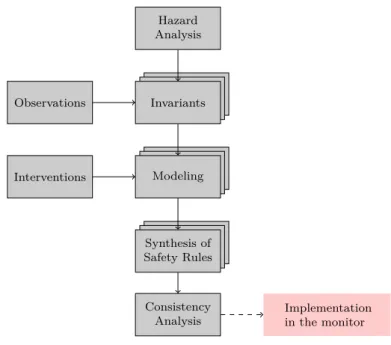
Figure 1.4: SMOF process
1.3
SMOF: Concepts and Tooling
From the diverse solutions presented before, the safety monitoring approach is a relevant candidate to keep an autonomous system in a safe state. We choose to adopt a reactive view: the monitor aims at preventing the reachability of catastrophic states, that are expressed by combinations of variable values. The monitor is assigned a high level of criticality and the logics it implements is kept simple. SMOF (Safety MOnitoring Framework) is a framework developed at LAAS, which we use and extend in our work. It provides a whole process to automatically synthesize safety strategies (using model checking) from invariants extracted from a hazard analysis. In this section we will explain the basic concepts of SMOF. Some examples will be shown in the next chapter where we will also discuss its limitations. For further information, the reader can refer to [Machin et al., 2018] and [SMOF, 2018].
1.3.1 SMOF Process Overview
The SMOF process overview is represented in Figure 1.4. The first step is to identify the potential hazards thanks to the HAZOP-UML analysis. From these hazards a list of invariants to be handled by the monitor is extracted. The invariants are then modeled: the observable variables are specified, as well as potential dependencies between them, the catastrophic state(s) and the available intervention(s). A template is available to ease the modeling, along with auto-completion modules. The synthesis algorithm provided by SMOF is launched in order to search for a suitable strategy. These same steps are followed for every invariant. Once a strategy is synthesized for each invariant, a
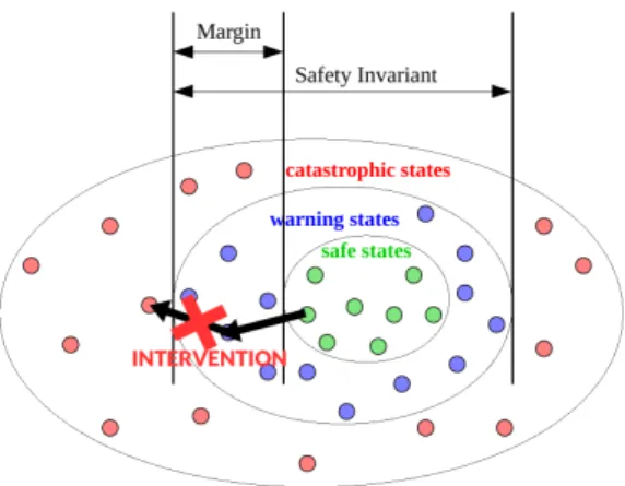
Figure 1.5: System state space from the perspective of the monitor
consistency analysis has to be performed, verifying that no conflict exists. The resulting set of rules can then be implemented in the monitor.
1.3.2 SMOF Concepts and Baseline
As a first step of the process (see Figure 1.4), one identifies a list of hazards that may occur during the system’s operation, using the model-based hazard analysis HAZOP-UML [Guiochet, 2016]. From the list of hazards, one extracts those that can be treated by the monitor, i.e., the monitor has ways to intervene to prevent the hazard from occurring. These hazards are reformulated as safety invariants such that each hazard is represented by the violation of an invariant. A safety invariant is a logical formula over a set of observable variables. Formulating invariants from the list of hazards can highlight the need to provide the monitor with additional means of actions (mostly actuators), that we call interventions, or additional ways to evaluate the environment and/or internal state (mostly sensors), that we call observations.
A combination of observation values defines a system state, as perceived by the monitor. If one of the safety invariants is violated, the system enters a catastrophic state that is assumed to be irreversible. Each safety invariant partitions the state space into catastrophic and non-catastrophic states as represented in Figure 1.5 (non-catastrophic states being the warning (blue) and safe (green) states). The non-catastrophic states can in turn be partitioned into safe and warning states, in such a way that any path from a safe state to a catastrophic one traverses a warning state. The warning states correspond to safety margins on the values of observations.
The monitor has means to prevent the evolution of the system towards the catas-trophic states: these means are a set of safety interventions made available to it. Most interventions are based on actuators, but they could also be software processes, e.g., processes filtering commands sent to the actuators. An intervention is modeled by its effect (constraint that cut some transitions) and preconditions (constraints on the state in which it can be applied). Interventions are applied in warning states in order to cut
all the existing transitions to the catastrophic states, as shown in Figure 1.5 by the red cross. Two types of interventions are identified in SMOF: safety actions that might change some state variables to put the system back into a safe state, and interlocks which forbid state variable changes (the system stays in a warning state).
The association of interventions to warning states constitutes a safety rule, and the set of all the safety rules constitutes a safety strategy. For example, let us assume that the invariant involves a predicate v < Vmax (the velocity should always be lower than Vmax). In order to prevent evolution towards Vmax, the strategy will typically associate
a braking intervention to warning states corresponding to a velocity higher than the threshold Vmax− margin. The determination of the size of the margin involves a
worst-case analysis, accounting for the dynamics of the physical system, as well as for the detection and reaction time of the monitor after the threshold crossing.
1.3.3 Safety and Permissiveness Properties
The safety strategy must fulfill two types of properties: safety and permissiveness prop-erties. Both properties are expressed using CTL (Computation Tree Logic) which is well suited for reachability properties. Safety is defined as the non-reachability of the catas-trophic states. P ermissiveness properties are intended to ensure that the strategy still permits functionality of the system, or, in other words, maintains its availability. This is necessary to avoid safe strategies that would constrain the system’s behavior to the point where it becomes useless (e.g., always engaging brakes to forbid any movement). SMOF adopts the view that the monitored system will be able to achieve its tasks if it can freely reach a wide range of states (e.g., it can reach states with a nonzero veloc-ity). Accordingly, permissiveness is generically formulated in terms of state reachability requirements: every catastrophic state must remain reachable from every other non-catastrophic state. This is called universal permissiveness. The safety strategy may cut some of the paths between pairs of states, but not all of the paths. In CTL, this is expressed as: AG(EF (ncstate)), for each non-catastrophic state. Indeed, EF specifies
that the state of interest is reachable from the initial state, and AG extends this to the reachability from every state.
The user can also use the simple permissiveness which merely requires the reachabil-ity from the initial state: EF (nc state). It is much weaker than the universal permis-siveness as it allows some of the monitor’s interventions to be irreversible: after reaching a warning state in which the monitor intervenes, the system may be confined to a subset of states for the rest of the execution. For example, an emergency stop can permanently affect the ability of the system to reach states with a nonzero velocity.
1.3.4 SMOF Tooling
The SMOF tool support [SMOF, 2018] includes the synthesis algorithm and a modeling template to ease the formalization of the different elements of the model: the behavior model with a partition into safe, warning and catastrophic states; the available interven-tions modeled by their effect on observable state variables; the safety and permissiveness
branch-and-bound algorithm that associates interventions to warning states and checks some criteria to evaluate if the branch should be cut or explored. It returns a set of both safe and permissive strategies for the given invariant to enforce. The formalization and strategy synthesis is done for each invariant separately. Then a last step is to merge the models and to check for the consistency of the strategies selected for the different invariants. The SMOF method and tool have been applied to real examples of robots: an industrial co-worker in a manufacturing setting [Machin et al., 2018], and more re-cently a maintenance robot in airfield [Masson et al., 2017], which will be described in Chapter 2. Examples and tutorials can be found online [SMOF, 2018].
1.4
Conclusion
Autonomous systems are evolving towards more diversity of missions and tasks, and are expected to share their workspace with humans. Consequently, they are highly critical systems and require means to ensure their dependability. Because of their complexity and the unstructured environment they evolve in, some faults remain and need to be tolerated, and we saw that monitoring is an appropriate way to do so. We are particularly interested in independent safety monitors, as they constitute the ultimate barrier before the occurrence of a catastrophic failure.
An important issue when considering monitors for autonomous systems is the spec-ification of the safety rules they implement. Indeed, they need to be defined using a dedicated method, that allows the association of the most appropriate reaction to a detected violation in order to cover an identified hazard. Due to the potentially high number of hazards to avoid, numerous rules can be synthesized and the consistency between them needs to be verified, as well as their implementation on the actual system. Also, the introduction of a safety monitor may have an impact on the system’s functionalities that needs to be identified and moderated. This is related to the choice of the recovery actions made available to the monitor: we saw that shutting down the system is not satisfying in the context of autonomy. This issue is not sufficiently addressed by the research community.
The framework SMOF, previously developed at LAAS, partially solves this problem by proposing a synthesis algorithm to automatically generate safety rules. However, it still suffers from limitations. The identification of such limitations is done in the next chapter, based on several cases studied.
• Autonomous systems are highly critical systems because of their inherent complex-ity and the unstructured environment they evolve in;
• Fault-tolerance has to be considered, as the complete removal of faults is not feasible;
• Independent safety monitors are an appropriate way to ensure the safety of au-tonomous systems;
• The specification of safety rules for monitors is challenging: they need to ensure safety while reducing as little as possible the system’s ability to perform its tasks; • SMOF has been introduced to solve the problem of synthesizing safety rules for independent active safety monitors. In this work we focus on cases where SMOF fails to return a satisfying solution.
Contents
2.1 Sterela Case Study . . . . 38
2.1.1 System Overview . . . 38 2.1.2 Hazop-UML Analysis . . . 39 2.1.3 Modeling and Synthesis of Strategies for SI1, SI2 and SI3 . . . 44 2.1.4 Modeling and Synthesis of Strategies for SI4. . . 51 2.1.5 Rules Consistency . . . 59
2.2 Feedback from Kuka Case Study . . . . 61
2.2.1 System Overview . . . 61 2.2.2 SII: Arm Extension with Moving Platform . . . 61 2.2.3 SIII: Tilted Gripped Box . . . 64
2.3 Lessons Learned . . . . 65
2.3.1 Encountered Problems . . . 65 2.3.2 Implemented Solutions . . . 68
2.4 Conclusion . . . . 69
SMOF (Safety MOnitoring Framework) has been developed to solve the issue of defin-ing safety rules for active safety monitors. It is a process for automatically synthesizdefin-ing safety rules from hazards identified during a hazard analysis.
The first objective of this chapter is to illustrate the SMOF method on a complete case study from the company Sterela. We will see that for complex examples, several iterations may be necessary to be able to synthesize a solution when none was found with the initial requirements. The second objective is to identify the cases where synthesis fails to return a satisfying set of rules and to analyze which features of SMOF are required to find solutions.
In Section 2.1, we will present and analyze the results of a case study provided by the company Sterela [Sterela, 2018], as part of the European project CPSE-Labs [CPSE-Labs, 2018]. To complete our analysis we will revisit some examples from a former experiment in Section 2.2, performed as part of the European project SAPHARI [SAPHARI, 2018], on a robot from the German company Kuka [KUKA, 2018]. The lessons learned from these two experiments are presented in Section 2.3, where we will present the identified limitations of SMOF, and explain the solutions that were manually