HAL Id: hal-01394139
https://hal.archives-ouvertes.fr/hal-01394139
Submitted on 23 Jan 2017
HAL is a multi-disciplinary open access
archive for the deposit and dissemination of
sci-entific research documents, whether they are
pub-lished or not. The documents may come from
teaching and research institutions in France or
abroad, or from public or private research centers.
L’archive ouverte pluridisciplinaire HAL, est
destinée au dépôt et à la diffusion de documents
scientifiques de niveau recherche, publiés ou non,
émanant des établissements d’enseignement et de
recherche français ou étrangers, des laboratoires
publics ou privés.
Autonomous Systems
Mathilde Machin, Jérémie Guiochet, Hélène Waeselynck, Jean-Paul
Blanquart, Matthieu Roy, Lola Masson
To cite this version:
Mathilde Machin, Jérémie Guiochet, Hélène Waeselynck, Jean-Paul Blanquart, Matthieu Roy, et al..
SMOF - A Safety MOnitoring Framework for Autonomous Systems. IEEE Transactions on Systems,
Man, and Cybernetics: Systems, IEEE, 2018, 48 (5), pp.702-715. �10.1109/TSMC.2016.2633291�.
�hal-01394139�
SMOF - A Safety MOnitoring Framework for
Autonomous Systems
Mathilde Machin, J´er´emie Guiochet, H´el`ene Waeselynck, Jean-Paul Blanquart, Matthieu Roy, and Lola Masson
Abstract—Safety critical systems with decisional abilities, such as autonomous robots, are about to enter our everyday life. Nevertheless, confidence in their behavior is still limited, par-ticularly regarding safety. Considering the variety of hazards that can affect these systems, many techniques might be used to increase their safety. Among them, active safety monitors are a means to maintain the system safety in spite of faults or adverse situations. The specification of the safety rules implemented in such devices is of crucial importance, but has been hardly explored so far. In this paper, we propose a complete framework for the generation of these safety rules based on the concept of safety margin. The approach starts from a hazard analysis, and uses formal verification techniques to automatically synthesize the safety rules. It has been successfully applied to an industrial use case, a mobile manipulator robot for co-working.
Index Terms—Fault tolerance, Safety, Autonomous system, Safety monitor, Model checking, Safety rules
I. INTRODUCTION
New safety critical systems are about to enter into our homes, work places or hospitals. These systems can operate without human intervention and take their own decisions, while performing tasks in human vicinity. Confidence in the safety of such autonomous systems, e.g., assistive robots, medical robots, or co-workers, is the main barrier to their deployment in everyday life. Indeed, many threats can af-fect the behavior of these systems and induce catastrophic consequences. Threats may come from faults in the design, from physical failures at run-time, or may be due to complex interactions with users or the environment. These systems have also to cope with many uncertainties in the perception of an unstructured environment. Attaining the required level of confidence calls for the combined utilization of a set of methods that can be grouped into four major categories [1]: fault prevention, fault removal, fault forecasting and fault tolerance methods. In this paper, the focus is on fault tolerance. No complex system can be considered as fault-free, and this is particularly true of autonomous systems having non-deterministic decisional software. Moreover, adverse and un-specified situations may also induce a hazardous behavior. Fault tolerance mechanisms are needed to deal with residual faults and adverse situations in operation. “Safety monitors” are one such type of mechanisms. Their role is to observe the system and its environment, and to trigger interventions that keep the system in a safe state. In practice, their specification
M. Machin, J. Guiochet, H. Waeselynck, M. Roy and L. Masson are with LAAS-CNRS, Universit´e de Toulouse, CNRS, UPS, Toulouse, France, e-mail: Firstname.Name@laas.fr.
J.-P. Blanquart is with Airbus Defence and Space, 31 rue des cosmonautes, F-31402 Toulouse, France
and design is usually done in an ad hoc manner. A very limited set of safety rules is considered, and interventions often have a permanent effect (e.g., if a bumper detects contact with an obstacle, it disconnects the power of a mobile robot). We argue that, in the future, versatile autonomous systems will have to deal with a richer set of safety rules, managing autonomously the activation and deactivation of temporary interventions. While ensuring safety, the rules should still permit functionality of the considered system, a property that we call permissiveness.
Extending previous work [2], [3], [4], this paper presents a Safety MOnitoring Framework (SMOF) to specify such rules, starting from a hazard analysis and using formal verification techniques to synthesize the rules. The synthesis tool, available online [5], accommodates both safety and permissiveness requirements. The paper also reports on the use of SMOF in an industrial case study.
The paper is structured as follows. Section II introduces baseline and concepts for safety monitoring and provides an overview of the proposed framework. Section III presents how the system and properties are formalized. Section IV explains the algorithm to synthesize the safety rules, using the NuSMV model-checker. Section V deals with the last step of the process to check the consistency of all synthesized rules. Section VI presents an application to a real industrial case study: it demonstrates the complete approach on a mobile robot, from hazard analysis to implementation of synthesized rules. Section VII discusses related work. We conclude in Section VIII, outlining the benefits and limitations of SMOF, and discussing future directions.
II. BASELINE AND CONCEPTS
A. Concepts
Taking inspiration from the diverse monitor defined by [6], we define a safety monitor as a device responsible for safety, in opposition to the main control channel which is responsible for all other functional and non-functional requirements of the system. The monitor is the ultimate protection against interaction faults or arbitrary behavior of the control channel that adversely affect safety. To this end, it is equipped with means for context observation (i.e., sensors) and able to trigger safety interventions. The whole safety channel must be assigned a high integrity level. In compliance with safety standards, there must be some degree of independence from the main channel. Moreover, the monitor should justifiably be able to trust the sensors and actuators it uses.
Assuming appropriate implementation means, our focus is on specifying the behavior of the monitor, i.e., on determining
which intervention should be applied, and when. Baseline concepts are the following.
A safety invariant (SI) is a sufficient condition to avoid a hazardous situation. We consider, conservatively, that if a safety invariant is violated, there is no possible recovery action. Thus, any state violating the safety invariant is a catastrophic state.
Example: “the robot speed shall not exceed3m/s” (the speed
beyond which harm is considered to be inevitable).
A safety intervention is an ability of the monitor to constrain the system behavior in order to prevent the system from violating a safety invariant. An intervention is only effective when its preconditions are satisfied. We distinguish two types of interventions: inhibitions and actions.
A safety inhibition prevents a change in system state. Example: “lock the wheels”, with “robot stationary” as a precondition.
A safety action triggers a change in system state. Example: “apply brake”.
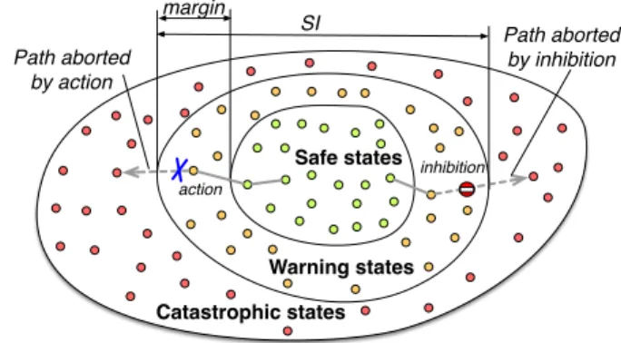
As recovery is not possible, interventions have to be applied before the catastrophe, i.e., in non-catastrophic states with some margin from the catastrophic border. Hence, the set of non-catastrophic states is partitioned into warning states, where interventions are applied, and safe states, in which the system operates without constraint (see Fig. 1). The warning states are defined such that every path from a safe state to a catastrophic state passes through a warning state.
A safety rule defines a way of behaving in some warning states. It is composed of a condition and an intervention to apply when the condition is true. The condition identifies a subset of warning states. The intervention is intended to abort catastrophic paths via these warning states.
Example: “if the robot speed is greater than2.5m/sthen apply
brake.” (taking a 0.5 margin below the safety threshold of 3m/s.
A safety strategy is a set of safety rules intended to ensure a safety invariant. It should abort all paths to the catastrophic states.
Example: “If the robot speed is greater than2.5m/sthen apply
brake; if the ground slope is greater than 10% then apply brake.”
The strategy specified for the monitor can be analyzed according to two antagonistic viewpoints.
Safety. The strategy is said safe if it ensures the safety invariant in the monitored system, i.e., it guarantees the non-reachability of the catastrophic states.
Permissiveness. The strategy is said permissive if the mon-itored system is able to freely move inside a specified state space. A maximum permissiveness would authorize all possi-ble states including catastrophic ones.
For example, a strategy allowing the system to operate at high speed, manipulating a sharp object in human presence, would be highly permissive but unsafe. Intrinsically, safety is ensured by reducing the possible behavior of the system: as soon as the monitor triggers an intervention, it reduces permissiveness. As autonomous systems are particularly ver-satile, they are supposed to operate in many different states.
Warning states Catastrophic states Safe states Path aborted by action Path aborted by inhibition ' action inhibition Warning states Catastrophic states Safe states ' action SI inhibition margin
Fig. 1. Partition of system states in catastrophic, warning and safe states.
Reactive layer Control channel Decisional layer SMOF framework Safety invariant formalisation HazOp/ UML Consistency analysis
(for all invariants)
Observation Intervention Variables observable by the monitor Interventions Safety invariant modelling Safety invariant modelling Safety invariant modelling Safety strategies Safety monitor Synthesis of safety strategy A N A L Y S I S R U N T I M E
Fig. 2. Overview of the process
To achieve the assigned tasks, the monitored system should keep its ability to reach a wide range of states.
In this paper, we propose a systematic approach to produce strategies that are safe but restrict permissiveness only to the extent necessary to ensure safety. Safety is ensured by the identification of safety margins, while permissiveness involves state reachability properties that can be tuned by the user.
B. Process overview
Figure 2 presents the overall process to use SMOF. The process starts with a HAZOP-UML hazard analysis [7]. In this method, the use of the system is modeled with UML use case and sequence diagrams. Each message is then analyzed with generic keywords such as “None”, “As well as”, etc. That results in deviations in the system, whose causes, con-sequences and severity are assessed, focusing on operational hazards. This analysis outputs safety invariants expressed in natural language. We consider as a running example a mobile robot with a manipulator arm and the safety invariant: The arm must not be extended beyond the platform when the platform velocity is greater thanV0.
Each safety invariant is then expressed formally with pred-icates on variables that are observable by the monitor. This second step may induce an early feedback on the system design, by revealing the lack of key observation mechanisms. We focus for now only on predicates involving variables compared to fixed thresholds. This type of safety threshold
is amenable to formal verification and is used in many real systems. Let us consider two monitor observations: the abso-lute speed v, and a Boolean observation of the arm position a (true when the arm is above the base, f alse when the arm is extended). The exemplary safety invariant is formalized as SI = (v < V0) ∨ (a = true). Its negation defines the
catastrophic states as v ≥ V0∧ a = f alse.
The third step is to build state-based models using the SMOF modeling template. In order to keep models simple enough to be validated, each safety invariant is modeled separately. In this step, we determine the partition of non-catastrophic states into safe states and warning states by splitting intervals or sets of variable values. This is done one variable after another. For example, the velocity interval [0, V0[
from SI is partitionable in two intervals according to a margin m: [0, V0 − m[ and [V0 − m, V0[. In the case of the arm
position, the observation is Boolean, hence no margin exists. The resulting model is shown in Figure 3. There are three warning states in which interventions may be applied. We consider two available interventions: the monitor is able to engage brake (action) and to prevent the arm from extending (inhibition).
The fourth step is the strategy synthesis. Figure 4 illus-trates a returned strategy, which applies brake in s1 and arm inhibition in s2 and s3. The interventions delete a number of transitions, the ones directly leading to the catastrophic state plus extra ones. As the system can still reach all non catastrophic states, the strategy is safe and permissive. When the model does not admit such a strategy, the user has several options: 1) reduce permissiveness, for example accept that a given warning state be no longer reachable; 2) add new interventions, which will have to be implemented in the real system; 3) modify the model, which may require revisiting the hazard analysis.
As safety invariants are processed separately, the fifth step checks the consistency of strategies that ensure different invariants. The checked set of strategies are then implemented in a real time safety monitor, for on-line verification.
The rest of the paper provides a detailed presentation of the steps supported by the SMOF template and tools: modeling, synthesis and consistency analysis. Then, the complete process is demonstrated on an industrial case study.
III. MODELING WITH ASMOFTEMPLATE
A SMOF model formalizes the part of the system related to one safety invariant, seen from the monitor’s point of view. It gathers all information necessary to produce strategies that ensure the safety invariant:
• Behavior: automaton of the system in absence of the monitor, containing all paths to the catastrophic states.
• Interventions: abilities of the monitor to constrain the system behavior.
• Safety and permissiveness: desired properties of the mon-itor action.
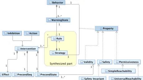
Fig. 5 gives a structured view of these concepts. The behavior contains warning states. A safety rule associates an intervention(or a combination of interventions) to one of these
W W W C S S v < V0-m ⋀ a = true v=0&a=1 V0-m ≤ v < V0 ⋀ a = true v=1&a=1 v ≥ V0 ⋀ a = false v=2&a=0 v ≥ V0 ⋀ a = true v=2&a=1 V0-m ≤ v < V0 ⋀ a = false v=1&a=0 v < V0-m ⋀ a = false v=0&a=0 s2 s3 s1
Fig. 3. Exemplary behavior model. There are two state variables: the velocity v∈ {0,1,2} encoding the partition {[0, V0−m[, [V0−m, V0[, [V0, Vmax[}, and the arm position a ∈ {0,1} encoding {true, f alse}. The warning states (labeled W ) are those that lead the system to the catastrophe C in one step.
W W W C S S v < V0-m ⋀ a = true v=0&a=1 V0-m ≤ v < V0 ⋀ a = true v=1&a=1 v ≥ V0 ⋀ a = false v=2&a=0 v ≥ V0 ⋀ a = true v=2&a=1 V0-m ≤ v < V0 ⋀ a = false v=1&a=0 v < V0-m ⋀ a = false v=0&a=0 s2 s3 s1
arm lock brake
Fig. 4. Exemplary behavior modified by a safety strategy
warning states. A strategy is composed of potentially many safety rules. Safety and permissiveness are properties attached to a pair of behavior and strategy. Since the behavior is a fixed part of the model, while the strategy is the varying part changed by the synthesis process, we will feel free to say that the strategy (rather than the pair) satisfies the properties. Validity is a side-property linked to the intervention preconditions (see Section III-B).
To formalize our model in this section, we choose to use languages and tools available in the model checking community. The synthesis presented in section IV is based on the model-checker NuSMV2 [8]. In what follows, code and output of NuSMV are given in typewriter font.
A. Behavior
The safety invariant involves observable variables compared with fixed values. The comparisons determine a first abstrac-tion of the variables into classes of values, e.g., the values that are below or above a safety threshold. The partition is then refined by the consideration for margins (formal conditions for the existence of a margin are studied in [2]). To ease the modeling in NuSMV, the resulting classes of values are encoded by integers, as illustrated by the state predicates in Fig. 3. For example, in the initial state, the class of values v < V0− m is encoded as v = 0 and overall the abstract
Fig. 5. Meta-model of the SMOF modeling template
version of v is in the range 0 . . . 2. The user must also enter a definition of the catastrophic states, with the predefined name cata. In the running example, this would be:
DEFINE cata := v=2 & a=0.
The behavior states result from the Cartesian product of the ranges of all abstract variables. The user does not need to list the states: NuSMV transparently builds the state space from the declaration of variables. By default, all the combinations of abstract variable values (i.e., states) are possible and all transitions between pairs of states are implicitly declared. The user can add constraints to delete states and transitions that would be physically impossible.
The most common constraint is the continuity of a vari-able, e.g., the velocity cannot “jump” from 0 (standing for [0, V0− m]) to 2 ([V0, Vmax]). The SMOF template provides
a predefined module Continuity to conveniently declare a continuous variable x. It encapsulates the constraint next(x) = x | x+1 | x-1, i.e., the next value of x can stay in the same interval or move to an adjacent interval, but it cannot jump from one interval to another that has no common boundary. SMOF also includes the predefined constraint that a catastrophe is irreversible, i.e. the cata states are sink states. The Cartesian product assumes that the variables are in-dependent from each other. If they are not, the user has to declare the dependency constraints. The ability to express them depends on the current abstraction. For example, let us consider two observable variables, position p and velocity v of a robot. To express the constraint that p cannot change when v = 0 (a very narrow interpretation of derivative), we need an abstraction distinguishing the concrete zero value of v from other values. In our running example, the partition would be too coarse, as all concrete values in [0, V0− m] are
encoded by the same abstract value 0. If a dependency is not modeled, the abstract model has less constraints than it should, or from another point of view, it has too many transitions. The over-approximation may affect the permissiveness analysis. However, if this “super-graph” is safe, so is the “real” model.
B. Interventions
An intervention is modeled by its effect and preconditions. The effect is a constraint that cuts some transitions from the current state state, to reduce the set of possible next states.
The effect is guaranteed only if the preconditions hold. We distinguish two preconditions. The State precondition, noted PrecondState, models the states in which the intervention can
be applied. For example, it is not desirable to physically lock the wheels of a moving vehicle. The strategy is said valid if it never applies the intervention in states violating PrecondState
(Validity property). The effectiveness of an intervention may also depend on the system history. We choose to only take into account the state preceding the application of the intervention, and consider a sequential precondition, noted PrecondSeq, that
must hold in this state. It constrains the transitions that trigger the intervention, when moving from a state in which the intervention is not applied to a state in which it is.
Fig. 6 gives an example of sequential precondition for the intervention “braking”. The intended effect is to avoid a concrete velocity greater than Vc. Let us consider two paths P1
and P2in the state space (we assume 9 abstract states). In each
case, the intervention is triggered upon entering the warning state W0. Along P1, the braking is triggered as soon as the
monitors detects the crossing of the margin threshold Vc−Vm.
The margin accounts for the sampling period of observation and worst case reaction time, so that the effect is guaranteed. On the contrary, along P2, the velocity can be arbitrarily close to Vc: there is no guarantee that the system has time to brake
before Vc is reached.
SMOF provides a predefined Intervention module, which could be used as follows to declare the braking pre-conditions and effect:
-- myInterv : Intervention(precondState, precondSeq, flag_myInterv, effect) brake : Intervention(TRUE, v=0 & next(v)=1,
flag_brake, next(v)!=v+1);
In this example, brake has no PrecondState(a TRUE value
is passed). The PrecondSeq parameter requires the braking
! v !c !c-!m vc-vm vc Δv1 Δv2 P1 P2 C v=2 v=1 v=0 a=0 a=1 a=2 S1 S2 S3 S4 W2 S0 W0 W1 initial values
Fig. 6. Example of sequential precondition: “braking is triggered by a transition from a state satisfying v < vc− vm”.
operator next). The effect is that the next value of v cannot increase. The flag_brake variable is a placeholder for the braking condition in synthesized strategies.
The module encapsulates a Boolean variable encoding the status of the intervention, currently applied or not. A pre-defined constraint states that the intervention is applied if and only if it is asked by the strategy (according to the synthesized flag) and the effect is guaranteed (according to the preconditions).
C. Properties
Safety and permissiveness properties are modeled in CTL (Computational Tree Logic), a branching time logic fully supported by NuSMV. Time along paths is modeled by three operators: X for a property to hold in the next state, G to hold on the entire path, F to hold eventually. The branching aspect is modeled by A, all the branches, and E, there exists a branch. A CTL operator is composed of one branching operator and one time operator. It is applied on states, or more generally on statements about the system state.
Safety is predefined as the unreachability of the catastrophic states declared by the user, i.e., in CTL, AG ¬ cata.
Permissiveness is modeled by two reachability properties applied to any non-catastrophic state snc:
• SIMPLEREACHABILITY: EF snc
The state sncis reachable from the initial state. • UNIVERSALREACHABILITY: AG EF snc
The state sncis reachable from any reachable state.
For safety, we pessimistically consider that several inde-pendent variables may change their values simultaneously. We call such simultaneous modifications diagonal transitions by reference to the two variable case (see Fig. 3, transition from initial state to s1). Relying on those possible but unlikely transitions to ensure permissiveness is not desirable as it would be too optimistic. A more complete definition of reachability properties that ignore diagonal transitions during permissive-ness checking is provided in [3] and used by the tools we developed.
The SMOF template has a LiveProp module defining the simple and universal reachability of an arbitrary state. A tool
Concepts User tasks Template NuSMV
Behavior
Continuity() VAR, TRANS
Dependence
cata
TRANS, INVAR Intervention Intervention Intervention() VAR, TRANS Permissiveness Validity Safety LiveProp() INVARSPEC CTLSPEC CTLSPEC Safety invariant DEFINE Partitions
Fig. 7. Concepts and implementation of the SMOF model
automatically instantiates it for each non-catastrophic state of the behavior model entered by the user. By default, universal reachability is required, but the user can edit a script to change the permissiveness requirements of some states. When the strategy synthesis returns no solution for the stringent requirements, it may be a good compromise to accept the simple reachability, or even the unreachability, of states that are not essential to the robot functionality.
D. Summary
The NuSMV model of our running example is given in Appendix A. This model is based on the SMOF template, available at https://www.laas.fr/projects/smof. The template includes predefined modules, parts to be edited by the user and generated parts. To model the running example, the user only needs to enter five lines, reproduced below, corresponding to the declaration of the abstract variables, of the catastrophic states and of the available interventions.
-- my var : Continuity(max,init) v : Continuity(2,0);
a : Continuiy(1,0); cata := v=2 & a=0;
-- myInterv : Intervention(precondState, precondSeq, flag_myInterv, effect)
brake : Intervention(TRUE, v=0, flag_brake, next(v)!=2);
lock_arm : Intervention(a=1, TRUE, flag_lock_arm, next(a)!=0);
Fig. 7 links the SMOF concepts, the user tasks, the template modules and the NuSMV syntactic elements. User tasks are required only for specifying the behavior and interventions. The properties are either predefined (safety) or generated (validity and default permissiveness). As can be seen in Appendix A, the tool also generates the list of warning states, i.e., of states having a transition to a catastrophic state. It is done in preparation for the synthesis of strategies: the warning states are candidate states for applying interventions.
IV. SYNTHESIS OF STRATEGIES
The synthesis algorithm takes as inputs the behavior model for an invariant, the available interventions and the properties to ensure (validity, safety, permissiveness). It outputs a set of alternative strategies, each of them satisfying the properties. Conceptually, a strategy assigns a combination of interventions to each warning state. Technically, this is encoded by the definition of flags in the model. In the running example, the
strategy applying brake in s1 and arm lock in s2 and s3 (see
Fig. 4) would be encoded as:
DEFINE flag_brake := flag_s1;
DEFINE flag_lock_arm := flag_s2 | flag_s3;
For a system with n warning states and m interventions, the number of candidate strategies is 2mn (accounting for all
possible combinations of interventions in the warning states). A naive algorithm could enumerate all the strategies, encode them one by one in the model and call NuSMV to check for the satisfaction of the properties. But such a brute force search would be very inefficient. Rather, our algorithm builds a tree of strategies, enabling us to prune branches during the search (branch-and-bound algorithm). A formal description of the tree and pruning criteria is presented hereafter.
A. Tree of strategies
Let I be the set of interventions, of size m, and IC = 2I the
set of intervention combinations. In the running example, I = {a, b} and IC = {a, b, ab, ∅} (abbreviating the set notation).
Let Sw = {s1, . . . , sn} be the set of warning states of the
behavior, of size n. A strategy N is a function that maps each warning state to a combination of interventions.
N : Sw→ IC
It is defined by a set of pairs N = {(s1, i1), . . . , (sn, in)}.
We say N is a satisfying strategy if it satisfies the va-lidity, safety and permissiveness properties. Furthermore, we focus on minimal satisfying strategies, i.e., strategies from which no intervention can be removed. A satisfying strategy N = {(s1, i1), . . . , (sn, in)} is minimal if there does not exist
a different satisfying strategy N0 = {(s1, i01), . . . , (sn, i0n)}
such that ∀k ∈ [1, n], i0k ⊆ ik. For instance, let N1 =
{(s1, ab), (s2, b)} and N2 = {(s1, a), (s2, b)} be satisfying
strategies. N1 is not minimal due to the existence of N2.
We now introduce the undefined combination of interven-tions noted ⊥, allowing us to consider partially defined strate-gies N : Sw→ IC∪ {⊥}. The search for minimal satisfying
strategies can then be seen as the exploration of a tree rooted by the undefined strategy N0 = {(s1, ⊥), . . . , (sn, ⊥)} (see
Fig. 8). Given a node N , building its children requires the choice of a state s↓ in which the interventions are not yet
defined, i.e., N (s↓) = ⊥. If no such state exists, N is a fully
defined strategy and a tree leaf. Otherwise, the children of N , noted Ni, are the 2mnodes such as ∀s 6= s↓, Ni(s) = N (s)
and Ni(s↓) = i, with i ∈ IC.
As shown in Fig. 8, subtrees are pruned during the search. Given the examination of a node N , the search may prune all its child subtrees (which is visualized by a cross under the node) and also some subtrees rooted by sibling nodes (visualized by dotted lines). More precisely, the pruned sibling nodes N0 exhibit a specific relation with the current node N , that of being a combined sibling. Let N and N0 be children of Np after choosing s↓. N0 is a combined sibling of N if
N0(s↓) ⊂ N (s↓). For example, let us consider the children
of Np = {(s1, b), (s2, ⊥), (s3, ⊥)} after choosing s↓ = s2:
the node {(s1, b), (s2, ab), (s3, ⊥)} is a combined sibling of
{(s1, b), (s2, a), (s3, ⊥)}. ¬perm ¬p_safe ¬p_saf e sat p_safe p_safe ¬safe ¬safe ↓ s =s3 ¬valid ↓ s =s1 {(s1,a),(s2,⊥),(s3,⊥)} {(s1,b),(s2,⊥),(s3,⊥)} ↓ s =s2 {(s1,∅),(s2,⊥),(s3,⊥)} {(s1,b),(s2,a),(s3,⊥)} {(s1,⊥),(s2,⊥),(s3,⊥)} {(s1,ab),(s2,⊥),(s3,⊥)} {(s1,b),(s2,b),(s3,⊥)} {(s1,b),(s2,ab),(s3,⊥)} {(s1,b),(s2, ∅),(s3,⊥)} {(s1,b),(s2,a),(s3,b)} {(s1,b),(s2,a),(s3,ab)} {(s1,b),(s2,a),(s3, ∅)} {(s1,b),(s2,a),(s3,a)}
Fig. 8. Examplary search tree. The chosen state s↓ is framed under the parent node. A cross indicates the pruning of all child subtrees, and dotted lines indicate the pruning of combined siblings. Nodes are labelled by the property determining the pruning.
The decision to prune subtrees depends on the properties satisfied by N . The strategy is thus encoded and model-checked. The encoding interprets the undefined interventions ⊥ as no intervention in the state. At the end of the tree exploration, the search returns all visited leaf nodes found to be satisfying strategies. In Fig. 8, the search would return a single strategy: the leftmost bottom node labeled sat.
B. Pruning criteria
Table I gives an overview of the pruning criteria.
The first criterion applies to a strategy N that is !valid. For instance, in Fig. 8, strategy {(s1, a), (s2, ⊥), (s3, ⊥)} is
!validbecause the intervention that locks the arm folded is applied in a warning state where the arm is unfolded. Child strategies of N define interventions in other warning states, but this will not fix the problem in the first one. Either the first warning state becomes unreachable, and so the child strategy is not permissive, or the state is reachable and the child strategy remains invalid. So, the children of an invalid strategy are either invalid or not permissive. Similarly, a combined sibling of N defines additional interventions in the same warning state, and the first intervention still makes the strategy invalid. Recursively none of the children of the combined siblings are solutions to the problem, we can prune the subtrees of the combined siblings.
Consider now a partial strategy that is not permissive. All its children are !perm as well, because adding interventions can only cut transitions. In the same way, its combined siblings are !perm. The second criterion prunes descendants and combined siblings of non-permissive strategies.
The third criterion detects partial strategies that cannot result in safe leaf strategies. It is evaluated using a subgraph of the behavior, where the warning states with undefined (⊥) inter-ventions are removed. For example, in Fig. 9, the subgraph does not contain s2 and s3. The safety analysis focuses on
reaching the catastrophic state via the warning states for which the interventions have been decided. If the strategy is safe in this subgraph we say that it is partially safe (p_safe). For example, the strategy of Fig. 9 is p_safe thanks to the effect of intervention b applied in s1. Now, suppose a strategy
is not p_safe. The defined interventions fail to remove all catastrophic paths in the subgraph. The descendants of the strategy will not remove these paths. They can only delete transitions from warning states that are currently outside the subgraph. So, all descendants are unsafe and can be pruned.
The usefulness of this criterion depends on how s↓is chosen
at each step of the tree building. In Fig. 9, the target strategy is a child of the root {(s1, ⊥), . . . , (sn, ⊥)}, after choosing
s↓ = s1. Suppose we had rather chosen s↓ = s3: any child
strategy would be trivally p_safe because s3 is unreachable
in subgraphs without s1 and s2. To avoid such cases, the
synthesis algorithm has a constraint on the s↓ chosen to build
the children of a node N . It must be such that N0is !p_safe, with N0 defined by:
N0(s↓) = ∅ and ∀s 6= s↓ N0(s) = N (s)
Under this constraint, the subgraphs are not trivially p_safe and the pruning by the third criterion is more efficient.
The fourth criterion, sat, which includes safety, validity and permissiveness, discards strategies that are not mini-mal. Assume N is a satisfying strategy. Its descendants and combined siblings might be sat as well, but they involve additional interventions and are thus not minimal. The corre-sponding subtrees can be pruned. N is appended to the list of solutions returned by the search.
The fifth criterion discards the non minimal strategies that are missed by the fourth one. For instance, in the tree of Fig. 8, {(s1, b), (s2, a), (s3, a)} is a satisfying solution. The fourth
criterion prunes its sibling {(s1, b), (s2, a), (s3, ab)}, but not
the non-minimal “cousin” {(s1, b), (s2, ab), (s3, a)}. The fifth
criterion is able to prune it at the time of the intervention decision for s2. It exploits the information that a current node
is p_safe, e.g., that {(s1, b), (s2, a), (s3, ⊥)} is p_safe.
Intuitively, no other intervention is needed in the subgraph. The criterion discards all combined siblings, like the sibling assigning ab to s2while a suffices.
Adding the fifth criterion ensures minimality of the returned strategies but may remove solutions. As soon as interventions have a PrecondSeq, their sufficiency for the subgraph does not
imply their sufficiency for the complete behavior. For example, in Fig. 9, assume that intervention b is not effective if the preceding state was s3: we may actually need an additional
intervention in s1to account for paths via s3.
Our synthesis algorithm can be configured into two variants, without or with the fifth criterion (see Table I). Variant 1 returns a superset of the set of minimal satisfying strategies. If it returns no solution, then it is sure that no solution exists for the model. If there are many solutions, this version is very long to execute as it explores all of them, plus a number of non-minimal ones. Variant 2 returns a subset of minimal satisfying strategies. It is not conclusive regarding the absence of solutions, but may return minimal strategies with a shorter tree traversal than Variant 1.
C. Evaluation using artificial models
We have developed a parallelized implementation of the synthesis tool. Its performance is assessed using artificial
TABLE I PRUNING CRITERIA
Synthesis Node property Prune relative nodes
V2 V1
1 !valid Descendants and combined siblings 2 !perm Descendants and combined siblings 4 !p_safe Descendants
3 sat Descendants and combined siblings 5 p_safe Combined siblings
W W W C S S v=0&a=1 v=1&a=1 v=2&a=0 v=2&a=1 v=1&a=0 v=0&a=0 s2 s3 s1 effect of b
Fig. 9. A view to check whether {(s1, b), (s2, ⊥), (s3, ⊥)} is p_safe. The states and transitions in plain line constitute the considered subgraph.
models. It allows us to consider search spaces with more than 1018strategies . The number of minimal solutions ranges from zero to thousands.
The models, listed in Table II, are generated as follows. One variable has 3 values, the others have 2 values. The initial state has all variables at value 0, and the only catastrophic state has variables at their maximum values. Each variable may be controlled by two interventions: an action that decreases the value of the variable, or an inhibition that freezes the value. The models consider various combinations of variables and interventions. For example, model 3var_3a has three variables controlled by decreasing actions only (suffix _a). Model 3var_3i has the variables controlled by freezing inhibitions only (suffix _i). Model 3var_6 has all six possible interventions. First, we did not consider sequential preconditions, and then we introduced some. Performance is assessed on a Intel Core I7-4770 processor running at 3.4GHz with 16 GB of memory.
Table II presents the results for interventions with no se-quential precondition. For each model, the number of complete strategies (i.e., of tree leaves) is given. It would be the number of steps of brute-force search. The two variants are assessed. Their first column allows a comparison to brute-force search: it gives the ratio of visited nodes (i.e., tree nodes) to the number of complete strategies, expressed as a percentage. It could be higher than 100%, since the tree nodes include both partial and complete strategies. But the observed values are very low, which demonstrates the overall efficiency of the pruning criteria. The second column gives the number of solutions found and the third column the execution time.
Since there is no sequential precondition, Variant 2 re-turns the exact set of minimal solutions. Both variants agree that models with actions only (suffix a) have no solution. Intuitively, as the actions force the variables to change, no permissive strategy can be found. For other models, Variant 1 keeps a large number of non-minimal solutions. The fourth criterion does not suffice to catch them, the fifth criterion
would be needed. As a result, Variant 1 explores a larger proportion of nodes and takes significantly longer times than Variant 2.
To check the undue removal of solutions by Variant 2, we must add sequential preconditions. We made several attempts, which we present briefly. We started by the following precon-ditions: the interventions of the 3-valued variable are effective only if the preceding state has this variable at 0. Synthesis was rerun. A post-processing function analyzed the solutions returned by Variant 1 to eliminate the non-minimal ones, giving the exact number of minimal solutions. Variant 2 found all of them in each case. We then strengthened the sequential preconditions with inter-variable dependencies. In addition to the previous conditions, the freezing intervention required one of the 2-valued variables to be at 1 in the preceding state; the decreasing intervention required the same variable to be at 0. It allowed us to observe the removal of minimal solutions. For example, for model 3var_6, there were 96 minimal solutions and Variant 2 returned 64. It was never the case that a model had solutions and Variant 2 returned none. We finally created a specific model, with preconditions referring to precise states, and managed to observe zero returned solution while there was one to find.
From what precedes, the best approach is to favor Variant 2, and to refine the results by using Variant 1 only in cases for which zero or few solutions are found.
Looking again at Table II, it may be surprising that the synthesis fails for a model with four variables (for variant 1) or takes half an hour (for variant 2). One might wonder whether the approach is useful in realistic cases. Firstly, the number of variables is not unrealistic. A safety invariant models only one safety-relevant aspect of a system. In the real system studied by [2], each invariant had no more than two variables. Secondly, the artificial models we used are generic, i.e., they have many interventions and no variable dependencies. It induces that there may be numerous solutions to find, much more than in real cases. This case is supported by the industrial case study in the next section. The models typically had one solution, and the longest synthesis time observed with Variant 1 was 0.32s.
V. ANALYSIS OF CONSISTENCY
Within our approach, each safety invariant is modeled sep-arately and has a dedicated safety strategy. To check the effect of merging the strategies retained for each invariant, the SMOF models are turned into NuSMV modules and gathered in one global model. A main module contains the glue information.
First, the variables from different SMOF models may be dependent. The user has to add the dependencies, in the same way as she entered them in SMOF models. A particular case of dependency is to use the same observation in two SMOF models. For example, consider an invariant of velocity limita-tion and another invariant using the informalimita-tion of whether or not the system is at stop. These invariants share a common observation, velocity, but they have a different partition of its values. The merging of the partitions follows a systematic approach illustrated in Fig. 10.
Local partitions
SI2: velocity limitation SI5: standstill Global partition 0 1 2 0 1 0 1 2 3 Platform Velocity Real Values
(a) Principle: form a global partition based on the real values
INVAR pf_vel=0 <-> si4.pf_vel=0 & si2.pf_vel=0; INVAR pf_vel=1 <-> si4.pf_vel=1 & si2.pf_vel=0; INVAR pf_vel=2 <-> si4.pf_vel=1 & si2.pf_vel=1; INVAR pf_vel=3 <-> si4.pf_vel=1 & si2.pf_vel=2; (b) Formal encoding: declare a global variable and glue constraints Fig. 10. Merging of two partitions of the platform velocity observation: for velocity limitation (Invariant SI2) and standstill determination (SI5).
Second, the launching of interventions has an impact on the whole system. Each time an intervention is asked by one local strategy, it may have an effect in all the SMOF models in which the intervention is modeled. The main module controls this by means of a global flag, defined as the disjunction of the local flags for this intervention. When the global flag is true, the effect of the intervention is determined in each SMOF model, under the local preconditions.
Analysis of consistency aims to check whether two strate-gies, synthesized from different invariants, apply incompatible interventions at the same time (e.g., braking and accelerating). The model-checker easily detects roughly inconsistent cases like both increasing and decreasing a variable. But there might be less obvious cases not captured in the abstract models. So, we require the user to specify the forbidden combinations. Given a pair of incompatible interventions (i, j), their non-concomitance is formulated as:
AG¬ ( globalF lagIntervi ∧ globalF lagIntervj)
Permissiveness is also re-checked. An intervention launched by one SMOF model could impair the reachability of states of other SMOF models.
VI. INDUSTRIAL CASE STUDY
To demonstrate our approach, we apply the whole process, from HAZOP analysis down to implementation, to a case study provided by KUKA Robotics.
The system is composed of a mobile platform and an articulated arm with 7 axis (see Fig. 11). It is an industrial co-worker in a manufacturing setting, sharing its workspace with human workers. It takes and places boxes, which contain parts, on shelves, tables, or on the top of the robot platform in order to convey them. A restricted area is defined, i.e., an area forbidden to the robot. The robot arm can be hand-guided when an operator needs to manipulate the gripped box to inspect it. This interaction phase begins and ends with an haptic gesture, a vertical push on the robot “elbow”.
The system is equipped with a safety layer satisfying most of the implementation assumptions of our framework. In particular, the programmable safety behavior associates inter-ventions with conditions on observation variables. Classically, only fixed thresholds are admitted to define the conditions.
TABLE II
EXPERIMENTAL PRUNING PERFORMANCE
Number Variant 1 Variant 2
Model of Visited Solutions Time Visited Solutions Time
strategies nodes (%) nodes (%)
2var_2A 64 4.7 0 50ms 4.7 0 50ms 2var_2I 64 12.5 1 230ms 12.5 1 150ms 2var_4 4 096 0.56 9 210ms 0.44 6 170ms 3var_3A 106 10−3 0 200ms 10−4 0 200ms 3var_3I 106 10−2 40 3.1s 10−3 12 1.0s 3var_6 1012 10−6 17 106 4min 10−8 1 128 18.3s 4var_4A 1018 10−14 0 3s 10−14 0 2.7s 4var_4I 1018 - - - 10−11 12 954 26min
Fig. 11. The mobile manipulator of KUKA
TABLE III
SAFETY INVARIANTS,RESULTING FROMHAZOP-UMLANALYSIS SI1 The velocity of robot arm must not be greater than V0. SI2 The velocity of robot platform must not be greater than V1. SI3 The robot must not enter the restricted area.
SI4 The robot platform must not collide with a human. SI5 The robot arm must not be extended beyond the platform
footprint when the platform moves.
SI6 A gripped box must not be tilted more than α0.
SI7 A collision between a human and the robot arm must not hurt the human.
SI8 The velocity of any point of the robot must not be greater than V2.
SI9 The robot arm must not drop a box. SI10 The robot arm must not clamp human parts. SI11 The robot gripper must not clamp human parts.
SI12 The robot must not override boxes laid on tables, shelves and robot storage.
SI13 The robot must follow the hand-guiding.
The monitor can observe a small subset of system variables and has two possible interventions: engaging the arm brake and engaging the platform brake.
A. HAZOP-UML
The system use cases have been modeled in 15 UML sequence diagrams. The HAZOP analysis results in more than hundred HAZOP lines with a non-zero severity. In practice, it does not mean that hundred safety invariants need to be modeled. There are many similar HAZOP lines that can easily be grouped. The analysis ends up with thirteen safety invariants listed in Table III.
B. SMOF models and synthesized strategies
In the following discussion, we put emphasis on how the approach is impacted by the limited observation and interven-tion means available to the safety layer. For this real system, some invariants had straightforward models, some required the
v < V0-m ⋀ a = false v ≥ V0 ⋀ a = false V0-m ≤ v < V0 W C S v < V0-m v≥V0
Fig. 12. Behavior of the SMOF model for SI1
elaboration of indirect observations derived from the direct ones, and some were impossible to address, pointing to a lack of observability or controllability.
1) Simple SMOF models: The first safety invariant, SI1, is the limit of the arm velocity, formalized by v < V0. Defining
the velocity of a robot arm with 7 axis is not obvious. The available observation v is the maximum translational Cartesian velocity among the velocities of the axis center points. The SMOF model is very simple, as there is only one observation, which admits a margin (see Fig. 12). A unique strategy is synthesized and, as expected, the arm brakes are engaged in the margin state. Safety threshold V0 and margin value have
been calculated by KUKA engineers. The SMOF model for the limit of the platform velocity (SI2) is similar.
2) Elaboration of indirect observations: SI3 states that the system has to stay away from the restricted area. The SMOF model uses one intervention, platform braking, and one observation variable, the difference between the distance to the restricted area (sensed) and the braking distance (computed from the platform velocity). The variable is not a direct observation but its computation from available observations is simple enough to be done in the safety monitor. Similarly to SI3, a collision between platform and human (SI4) is avoided by observing the difference between the braking distance and the distance to any obstacle (sensed by laser).
SI5 inspired our running example: The arm must not be extended beyond the platform when the platform moves. In the real system, the safety layer can observe whether all points of the arm are inside a rectangular area defined by the user. The area corresponding to the footprint of the platform gives us the safety threshold: if any arm point is outside this area, the arm is extended. To take a margin, we define an inner rectangular workspace (see Fig. 13). The arm position can then be encoded by three values, depending on the observations for the two areas. Platform velocity is observed as a Boolean variable (0 for standstill, 1 for movement) with no margin.
For this invariant, both interventions are relevant. The margin of the arm extension (i.e., the distance between the two workspaces) is based on the braking distance of the arm. To
Inner work space Outer workspace (a) Workspaces XX XX XX XX Outer Inner inside outside inside 0 1 outside - 2
(b) Values of the observed arm position Fig. 13. Observation of the arm extension.
ensure that the arm will not reach the outside of the platform, the braking must be engaged as soon as the border of the inner workspace is crossed. Hence, arm braking has a sequential precondition (the preceding state is such that arm_pos=0). The platform braking has no sequential precondition but a state one. It prevents the platform from starting if applied in a state where it is already standstill. Given the inertia of the platform and the brake power, it is not possible for the initially standstill platform to reach any significant velocity between the time of the braking command and the time when brakes are effectively engaged. Hence, the platform braking can be seen as instantaneously effective, ensuring next(pf_vel)=0.
The synthesized strategy is to brake the platform when the platform is standstill and the arm is close to or beyond the footprint limit. The arm brake is engaged when the platform is moving and the arm is in the margin.
3) Elaboration of hypothesized values: In some cases, the state variables of interest cannot be derived from observations, their value must be hypothesized based on the observations, in a conservative way.
SI6: A box in the gripper must not be tilted too much. The arm is able to pick boxes containing parts. As the boxes have an open top, parts may fall if the box is too much tilted. To formalize this invariant, the required observations are 1) the presence of a box in the gripper; 2) the angles (or the maximum absolute angle, denoted alpha) of the gripper with respect to the Cartesian x and y axes. While alpha is observable, the presence of a box is not. We make the assumption that the gripper takes a box when the end-effector is close to the robot storage and the gripper closes. (For sake of simplicity, we only consider here the case of the robot storage, and exclude the cases of tables and shelves). The box is released when the gripper opens. Hence, our modeling involves a hypothesized state variable, box, that is updated according to the observation of the gripper status (open, close) and the distance z to the storage from close (= 0) to far away (= 2).
The safety property is first formulated as cata := alpha=2 & box=1, i.e., the gripper presumably carries a box and the angle is above the safety threshold. The synthesis returns no result. The monitor is indeed not able to prevent the direct transition form the warning state alpha=2 & z=0 & gripper=open & box=0 to cata. In this case, making parts fall close to the robot storage is not very hazardous because they fall from a low height. The new version of the safety property is cata := alpha=2 & box=1 & z=2.
The synthesis returns one strategy that is to brake the arm when a box is in the gripper, the end-effector is in the margin distance or far from the robot storage, and the angle is greater than the margin threshold.
Another example is SI7. The collision between the arm and a human being is hypothesized via the arm velocity and the external torque, computed from the torques sensed and a physical model of the arm (mass and geometry, internal torques from weight and intended acceleration). An adequate strategy is synthesized.
4) Unsuccessful cases: Invariants SI8-13 were not ad-dressed due to lack of observable variables or interventions. For example, the vectorial sum of platform and arm velocities is not observable (SI8). An intervention to lock the gripper would be necessary to prevent box dropping (SI9). In many observability issues, the relevant variables could have been indirectly derived from existing observations, but in a way that was deemed too complex: the derived information would not be trustable enough to be used by the safety monitor. A relevant example is the hand-guiding of the robot (SI13). Checking whether the arm follows the intended movement would be computationally expensive (accounting for the move-ment and torques sensed on all axes) and untrustable. As the interaction protocol begins and ends with haptic gestures, the monitor could not even trustily determine that a hand-guiding phase is ongoing. A solution would be to simplify the protocol (e.g., by using a push button), and to replace SI13 by a stringent limitation of arm velocity and acceleration during hand-guiding. It would ensure that the robot is harmless whether or not it correctly follows the guiding.
By providing feedback on the safety invariants that can or cannot be ensured, our approach can help the designers to modify the critical features of the system in the early stages.
C. Analysis of consistency
The SMOF models and strategies for SI1-7 are gathered in one global model. The partitions of arm velocity (from SI1 and SI7) and platform velocity (from SI2 and SI5) are merged as exemplified by Fig. 10. The triggering of arm braking and platform braking are synchronized: as soon as one SMOF model triggers a brake, the main module triggers the same brake in all SMOF models (with an effect that depends on local preconditions).
The consistency analysis checks that incompatible inter-ventions are not applied at the same time. In this system, there are only two interventions and they are not incompatible. We nevertheless checked their non-concomitance and NuSMV returned a counterexample. But again, no issue is raised by a concomitant application of arm and platform braking. The global model also passed the permissiveness checks.
D. Implementation and tests
For demonstration purposes, we implemented and tested the synthesized strategies on a KUKA robot.
TABLE IV
DEFINITION OF TEST CASES AND RESULTS OF THEIR EXECUTION
Definition of test cases Executions Assessment
Number Description Test objective Monitor Arm
braking Platf. braking V iolated SI Test verdict 0 Arm movement (above the inner workspace), then platform
move-ment. Permissiveness
No
PASS Yes
1 The controller tries to reach an arm velocity that is above the safety
threshold, with a normal acceleration. SI1
No SI1
PASS
Yes √
2 The controller tries to reach an arm velocity that is above the safetythreshold, with a high acceleration. SI1 YesNo √ SI1SI1 FAIL 3 The controller tries to reach a platform velocity that is above the
safety threshold, with a normal acceleration. SI2
No SI2
PASS
Yes √
4 The controller tries to reach a platform velocity that is above thesafety threshold, with a high acceleration. SI2 YesNo √ SI2SI2 FAIL
5 The controller tries to reach the restricted area. SI3 No SI3 PASS
Yes √
6 During the platform movement, the arm moves and goes outside theplatform footprint. SI5 YesNo √ √ SI5 PASS 7 During the arm movement, the arm goes outside the footprint and
stops there. Then the platform moves. SI5
No SI5
PASS
Yes √
8 During the platform movement, the arm moves above the innerworkspace. Permissiveness (SI5)
No
PASS Yes
9 The arm moves beyond the platform footprint, and comes back to stop above the inner workspace. Then, the platform moves.
Permissiveness (SI5)
No
PASS
Yes √
1) Experimental constraints: The experiments are done on a real system in the environment of the KUKA laboratory. As a consequence, experiments requiring collisions with a human being are dangerous. We were not able to test the strategies corresponding to the collision with the arm (SI7) and the platform (SI4). Furthermore, the robot made available to us had no gripper, making it impossible to implement the strategy of SI6. Finally, we did not have programing access to the safety layer. We had to implement the strategies in a separate thread in the high-level Java interface of the system. It does not provide us the same guarantees as the safety layer would, in particular as regards real-time behavior.
2) Test cases: To test the strategies, we define a base case: from an initial standstill position, the arm moves above the inner workspace, stops, and then the platform moves. All other test cases introduce a deviation from the base case that targets a safety invariant. The first column of Table IV presents the test cases and the associated test objectives.
When the objective is to test permissiveness, the behavior of the robot controller is not dangerous and should not be disturbed by the monitor. The base case serves this objective, as do Cases 8 and 9. Case 8 checks that the arm is free to move during platform movement, as long as it stays above the inner workspace. Case 9 checks that the platform is free to move after the arm is back to a safe position.
When the objective is to test safety, the behavior is danger-ous and the monitor must avoid the violation of an invariant. Cases 1-4 test a velocity too high, of the arm or the platform, reached with normal or high acceleration. Case 5 moves the platform into the forbidden area. Cases 6-7 let the platform move with the arm in a dangerous position. Either the arm unfolds as the platform moves (Case 6), or it is stopped at a dangerous position before the platform moves (Case 7).
3) Results: Each case is tested twice, with and without the monitor. Table IV reports the triggered interventions and violated invariants. The safety of the runs is also controlled visually by the operator. The final Pass or Fail verdict depends on the test objective.
For permissiveness, a test case passes if the run without the monitor is safe, and the other run with the monitor has a similar behavior (similar execution time, similar final position of the arm and the platform, no spurious intervention). Cases 0, 8, 9 all have a Pass verdict. For Case 9, note that the platform braking is not a spurious intervention. It is applied at the beginning of the run, when the arm is extended and the platform should not move. But the braking is no longer active when the platform really moves later in the run.
For safety, a test case passes if the execution is unsafe without the monitor and becomes safe with it. Two of the test cases fail, those checking velocity thresholds with a high acceleration. The adequate intervention is triggered too late to be effective: there is a transient threshold overrun before velocity decreases. The problem is mainly due to experimental constraints, since we were not allowed to use the real-time safety layer. The margin values rely on the input sampling rates and bounded intervention delays, but the Java implementation does not ensure them. We repeated Cases 2 and 4 several times and the real-time behavior varied. In one execution, the monitor did not even observe the traversal of a warning state: its inputs directly jumped from a value lower than the margin threshold to a value greater than the safety threshold, following a path that does not exist in the SMOF model.
These fail cases underline the criticality of the calculation assumptions taken for margins. They concern not only the dy-namics of the system (e.g., its maximal acceleration) but also its data processing part. Indeed, no margin can be calculated
if the processing has an unpredictable real-time behavior. In a realistic setting, the monitor should be in the safety layer.
Putting aside the real-time issues of the Java-based imple-mentation, the experimentation revealed no other problem. As far as the strategies could be assessed given the experimental constraints, they were found safe and permissive.
VII. RELATED WORK
In dependability community, fault tolerance defined by [1] as the means to avoid service failures in the presence of faults, is carried out with error detection and recovery mechanisms. This approach has been used in robotics architecture, at functional level [9] or decisional level [10], [11] for instance. A popular form of fault tolerance dedicated to safety is safety monitoring, through which the functional system is forced to a safe state (recovery) should some hazardous behavior be detected (error detection). Safety monitors appear in the literature under many different terms, such as: safety kernel [12], safety manager [13], autonomous safety system [14], checker[15], guardian agent [16], safety bag [17], emergency layer [18] or diverse monitor [6].
A quite similar approach can be found in the Runtime Ver-ification community [19], where verVer-ification techniques (e.g., theorem proving or model checking) are used to check whether a run of a system under scrutiny satisfies or violates a given property. Most of the work deals with non independent layers, focusing on code instrumentation, with dependency issues between the safety layer and functional layer. Nevertheless, in [20], [21], [22] the independence or isolation issue is tackled. It is also important to mention supervisor synthesis devel-oped by [23], which is focusing on delivering a correct-by-construction controller. Using our terminology, it is actually a way of integrating in the functional controller only inhibitions to remove unwanted transitions (and not actions). Conceptu-ally similar to supervisor synthesis, the work in [24], presents a synthesized robot controller integrating properties. Again, no rules identification process is proposed, authors focus on the verification mechanism. This approach is also based on the knowledge of the functional controller behavior, which is not the case in this paper.
Even if those latter works can be extended to the devel-opment of dedicated safety layers, no process for safety rule production is studied. Most of the work focuses on language theory issues. We also study and integrate in our framework the necessary compromise between, safety and permissiveness, which is not addressed in the previous papers. Among previous cited safety monitors, a close work presented by [15], proposes to add a layer in an autonomous robot controller software to detect and recover from deviations between requests from the decisional layer and observations coming from the functional layer. But most of the work was to create a generic mechanism to produce code for the execution layer, and not to provide a tool for the identification of the properties to check. [25] pro-pose to guarantee safety using several hardware and software redundancies, but no systematic approach is proposed.
For the safety rule identification process, [26] present a very similar workflow to ours. They use HAZOP to identify
hazards and determine (intuitively) the corresponding safety rules, which are if-then-else rules. From sensor observations, the monitor (safety layer) sends actuation inhibitions to both the controller and the software actuator interface. The main point of the method is to take into account sensor uncertainty. Compared to our approach, permissiveness is implicit and the monitor is actually dependent from the functional layer. The safety rules consistency issue is mentioned in [27] and [28], but again, a systematic process is actually out of the scope of these works.
VIII. CONCLUSION
Active safety monitors for autonomous systems have to deal with complex safety rules, inducing several interventions that should be consistent. To develop such active monitors, we proposed a formalized process based on the definition of warn-ing states linked to a safety margin. In these warnwarn-ing states it is possible to trigger interventions before the system goes in catastrophic states. We proposed a complete framework, SMOF, starting from hazard analysis and ending in safety rules synthesis. In this paper, we particularly focus on the safety rule generation algorithm, and on its validation on a real industrial case study.
A major benefit of SMOF is that it provides a systematic and formal approach for the expression of safety rules, whereas it is usually done ad hoc, based on the expertise of the analysts only. The models are also of great importance to describe the monitor behavior in order to take it into account for the development of the functional layer. Indeed, safety margins and interventions need to be non-ambiguous to determine controller reactions. Our approach is based on the use of a well-known formal language (CTL), and we proposed a template available online to simplify the use of our tool. Most of the complex verifications (like permissiveness) are automatically generated and checked. More precisely, for the selection of intervention, we propose to take into account the warning state where the system is, but also the path followed to reach this state. A last notable result is that after application on a real use case, there is no combinatorial explosion of the algorithm, and its performance is acceptable.
A main limitation of using our approach lies in the ex-pression of dependencies or partitions of observable variables. Indeed, the efficiency of the generation could be highly increased when the analyst has a good level of expertise on interrelations between variables. Another drawback is that the current version of SMOF does not include a mechanism to activate/deactivate the safety rules depending on the task performed by the system. In most of autonomous applications, this would represent an important issue as systems tend to be more and more versatile. The proposed approach is also limited to the functional level, with simple expression of the safety invariant using propositional logic. For now, we do not consider interventions like blocking requests from decisional layer.
Future directions concern the extension of the framework to the definition of a several warning regions, in order to trig interventions with different levels of efficiency. For instance,