HAL Id: hal-01447396
https://hal-imt.archives-ouvertes.fr/hal-01447396
Submitted on 26 Jan 2017
HAL is a multi-disciplinary open access
archive for the deposit and dissemination of
sci-entific research documents, whether they are
pub-lished or not. The documents may come from
teaching and research institutions in France or
abroad, or from public or private research centers.
L’archive ouverte pluridisciplinaire HAL, est
destinée au dépôt et à la diffusion de documents
scientifiques de niveau recherche, publiés ou non,
émanant des établissements d’enseignement et de
recherche français ou étrangers, des laboratoires
publics ou privés.
Finding Objects Faster in Dense Environments using a
Projection Augmented Robotic Arm
Hind Gacem, Gilles Bailly, James Eagan, Eric Lecolinet
To cite this version:
Hind Gacem, Gilles Bailly, James Eagan, Eric Lecolinet. Finding Objects Faster in Dense
Environ-ments using a Projection Augmented Robotic Arm. INTERACT’15: IFIP International Conference on
Human-Computer Interaction, Sep 2015, Bamberg, Germany. pp.221-238,
�10.1007/978-3-319-22698-9_15�. �hal-01447396�
Finding Objects Faster in Dense Environments using a
Projection Augmented Arm
Hind Gacem1,2, Gilles Bailly2,1, James Eagan1,2, Eric Lecolinet1,2 1Télécom ParisTech, 2CNRS LTCI UMR 5141, Paris, France
Abstract. Locating an object in an unfamiliar and dense physical environment, such as a
control room, supermarket, or warehouse, can be challenging. In this paper, we present the
Projection-Augmented Arm (PAA), a motorized robotic arm augmented with a pico-projector to
help users to localize targets in such environments. The arm moves and displays a projected spotlight on the target. We present the results of a study that shows that the PAA helps users to more quickly locate target objects in a dense environment. We further study the influence of the visibility of the projected spotlight while moving versus that of the physical movement of the projection arm on user performance and search strategy, finding that 1) information about the orientation of the arm has a stronger impact on performance however following the moving spotlight on the walls did not significantly improve performance; 2) the orientation of the arm is especially useful when the target is behind the user (36.33 % improvement); and 3) users’ strategies relied mainly on the arm when it is visible.
Keywords: Guidance techniques, augmented arm, steerable pico-projector.
1.
Introduction
Finding and locating physical objects can be challenging, especially in dense envi-ronments such as control rooms, supermarkets, warehouses, etc. These envienvi-ronments may contain several hundreds or even thousands of objects, which may look similar and be spread about the space, including behind the user. Even when the user knows what the target looks like (e.g. color, shape, size, etc.) and has a general idea of the organization of the space, finding an object in such an environment is already diffi-cult. Even in such situations, one might look several times over several areas before finding the target, such as when looking for, say, a yoghurt pot in the refrigerator. For unfamiliar targets or unfamiliar environments, locating an object can be even more challenging. Generally, one must first orient oneself to find the general vicinity of the target and then perform a visual search on this area to pick out the target.
Although this localization task occurs frequently in many application areas (maintenance, training in control rooms, libraries, warehouses, etc.), proposed guid-ance techniques for such environments [2,10,19,20,21] focus separately on how to help the user to orient himself or how to show him precisely the location of the target, but not both.
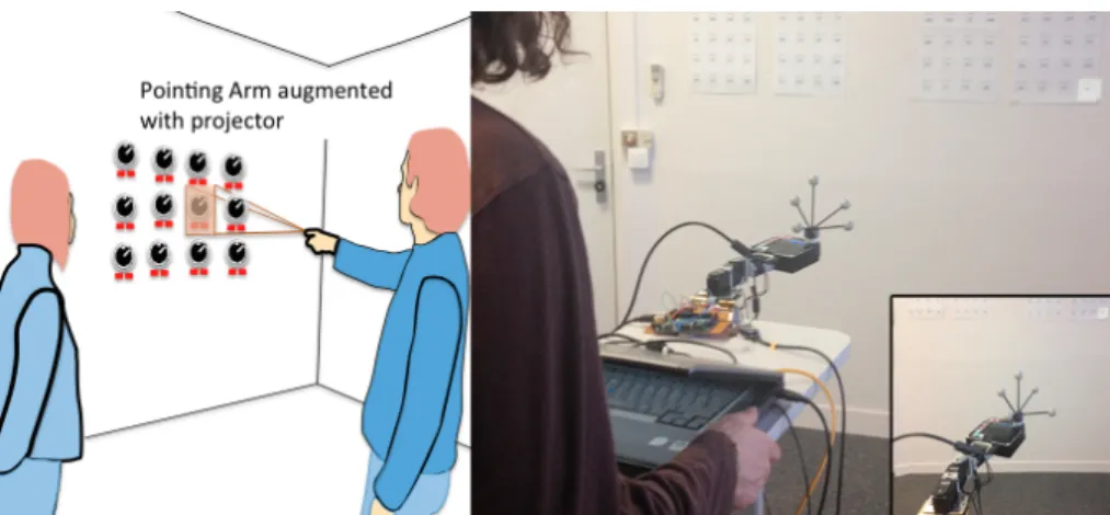
Figure 1: (a) The metaphor of the PAA: a user points to a specific component on the wall, which contains several similar targets. The observer follows the direction of the user’s pointing arm, which is augmented with a projector to
precisely highlight the target. (b) The PAA prototype. A user fills out a form on a rolling table, on which an automated arm is fixed and projects toward the de-sired target on top right of the wall.
Existing work mainly focuses on outdoor way-finding and guidance techniques for people with visual impairments [4,5], for small environments [14,18,22,23] and/or guidance techniques requiring instrumenting users (e.g. with a head-mounted display (HMD)) [12,29], which may be cumbersome, expensive, and sometimes incompatible with other constraints. Our goal is to provide guidance support to help users to orient themselves and to precisely locate targets in dense environments, such as controls in a control room, by augmenting only the environment and not the user.
In this paper, we introduce the Projection Augmented Arm (PAA), illustrated in Figure 1 (b) and in Figure 2 (b). It consists of a motorized arm with a pico-projector mounted on the end to project a spotlight on a given target. It can be mounted to a cart (e.g. a shopping cart in a supermarket or to a delivery cart in a warehouse) in front of the user (Figure 1 (b)) or handled by the user to allow multiple usages. The design of the PAA draws inspiration from the way that humans gesture toward targets by point-ing. An observer can easily recognize the general direction of the target without look-ing directly at the arm of the person pointlook-ing it out. However, because pointlook-ing at an object is insufficiently precise, we extend the arm with a projected spotlight, as if the person were carrying a flashlight in her hand (Figure 1 (a)).
The design of the motorized arm (1) offers a large projection surface: the projector can target anywhere in area from 0 to 300-degrees horizontally and vertically. More-over, by placing the arm within the user’s field of view, (2) the general direction of the target remains visible in the user’s peripheral vision, thus (3) reducing the search area by orienting the user toward the desired object while (4) the spotlight precisely indicates the location of the target. Moreover, the projector could display additional information around the target, using the same device. It is straightforward to attach the system to a cart, making it (5) mobile. Further, it (6) alleviates occlusion problems
and (7) can be less intrusive than guidance techniques requiring users to wear addi-tional devices such as glasses or HMDs. Finally, (8) PAA may be visible by several users simultaneously when performing a collaborative task.
In a pilot user study, we confirmed our intuition that providing a coarse guidance via the pointing arm coupled with the precise guidance of the projector did indeed improve performance on object localization tasks. We then conducted a follow-on user study to better tease out the impact of having a physical pointer perceivable in the periphery. More precisely, we investigated the influence of the projected spotlight versus the physical movement of the projection arm on user performance and search strategy. Results show 1) information about the orientation of the arm has a stronger impact on performance. However, following the moving spotlight on the walls did not significantly improve performance; 2) the orientation of the arm is especially useful when the target is behind the user (36% improvement); and 3) users mainly relied on the arm for guidance in conditions where it was visible.
Our primary contributions are:
1. An application of the metaphor of the way humans use pointing to orient each other for improving guidance techniques.
2. The design and implementation of PAA, a mechanical, motorized pico-projector for localizing physical targets in dense environments.
3. Findings of a user study investigating the influence of the projected light versus the physical movement of the projection arm on user performance.
2.
Informative Study
Our primary context of interaction is control rooms of nuclear plants. To better un-derstand the specificities of this environment, we conducted both observations as well as interviews with five domain experts.
We learned that these control rooms are quite large and contain numerous panels densely filled with buttons, gauges, and alarm indicators that are difficult to quickly distinguish, especially for novice users (typically, people performing maintenance or when training novice or experienced operators on a new type of control room). The environment can be noisy and is manned by several personnel who move about the room. Moreover, operators generally bring with them a wheeled high-top table to transport documents.
Regarding the task, we learned that operators typically follow a paper procedure document, which references the appropriate controls. Paper is used rather than an electronic device for safety and verifiability reasons. This document is generally placed on a high-top table cart, which also serves to store auxiliary documents. For each step of the procedure, operators first move with the cart to the position of a spe-cific element in the room and then take notes according to the configuration of this element on the paper procedure (e.g. to mark that a button has been pressed, report the value of a sensor, etc.).
1. Users should be able to move about freely. Not only must they roam around the control room, but their hands must also be free to manipulate pens and various documents (they may have to find supporting information in other documents, including large books with complex diagrams).
2. Users’ senses should not be obstructed. In particular, audio does not seem an appropriate modality in such a noisy environment and in which operators fre-quently communicate.
3. Glasses and HMDs are problematic for the same reason. The operator must main-tain an environmental awareness and be able to rapidly detect any visual alarm, regardless of the panel it is displayed on. Moreover, operators often work in pairs, and, occasionally, in larger groups. It is thus convenient and advantageous to use equipment that several people can see simultaneously. This is also less constraining for the people working permanently in the control room (they do not have to wear a device all day long) and for those working in several rooms (they do not have to put on and take off a device multiple times). Augmenting a cart or wheeled table offers a straightforward solution to these problems.
4. The guidance system should accommodate multiple operators. In particular, some operators may temporarily occlude some elements with their body. Moreover, the guidance system should minimize the disruption of other operators. Hence, on the one hand, people working together should all be able to see the system, but, on the other hand, other people should not be bothered by the system.
5.
Due to the size of the room and the density of the elements, the guidance system should be precise enough to unambiguously identify a single 3cm × 3cm control in a control panel.Because of this specific context of use, we focused the design of the PAA for command and control rooms. Nonetheless, we believe our guidance approach can be readily generalizable to other contexts such as a supermarket, a warehouse or a li-brary. As in our case, these are dense environments where it is difficult to augment objects and where users often use carts (either a shopping cart, a library shelving cart, or a warehouse delivery cart).
3.
Related Work
3.1. Guidance Techniques
Guidance techniques have been proposed for a variety of purposes. Generally, they can be categorized in terms of the granularity of the guidance they provide: from helping the user to navigate within a space (e.g. by moving one’s feet) to helping her to orient herself (e.g. turning in place) [12] to precisely locating a target in front of the user (e.g. visual search) [2,27]. The PAA focuses on these last two categories.
Body/Head Orientation. Several techniques have been proposed for orienting the
user toward a given direction using different modalities. For example, Yamano et al. [32] rely on sound (frequency or amplitude panned sound), while Erp et al. [8] rely on
haptics by using a vibrating waist. As our technique should work in noisy areas and allow for precise localization, we focus on visual guidance techniques (e.g. [12,20]).
Precise Guidance techniques generally help the user to find a target that is already
in his/her field of view. Again, the use of audio [27] and haptics [18] has been consid-ered, but vision is more appropriate in our case as in [2] where a steerable projected spotlight highlights a target. The projector is, however, ceiling-mounted, outside the view of the user. As such, it provides precise guidance, but does not provide orienta-tion guidance to help a user who might be facing in the wrong direcorienta-tion.
Few techniques support both of these guidance granularities. Henderson and Feiner [12] use left/right arrows displayed on augmented reality goggles to help orient the user. Once the target is in the field of view of the user, a 3D virtual arrow directly points to the target in the glasses, providing for precise guidance. This technique is promising, but requires the user to wear additional equipment, notably augmented reality glasses. Gröhn et al. [9] combine 3D sound to help orient the user with a spot-light to precisely locate a target, but the use of sound precludes this approach from noisy environments in which the user cannot wear headphones. For the reasons ex-plained in Section 2, our goal is to provide guidance without requiring the user to wear special equipment. Control rooms may have strict safety requirements that pre-vent the use of such equipment, as in our direct case. In supermarkets or libraries, providing clients with a cart is feasible whereas requiring them to share wearable devices may not be.
3.2. Projector-based Augmented Reality
Based on these considerations, we now focus on projector-based techniques that do not require the user to wear any special equipment such as augmented reality glasses or Google glasses. From the literature review, we have identified two main dimen-sions: whether the projection system is motorized or not, and whether it is fixed (the environment is augmented) or not fixed (the user is augmented).
Table 1 Motorized vs. Fixed Projection Systems.
Motorized projection system
Yes No
Fixed projection system
Yes PAA, [3,16] [2,7,25,26,31]
No [11,24,30] [6,15]
Fixed Projectors without a motorization system. Single-projector solutions can
only project on a limited surface area. They may also be susceptible to occlusion if a person or object passes between the projector and the projection surface. To over-come these limitations, Jones et al. [15] enlarge the projection area and minimize occlusion problem by deploying several fixed projectors in a room with shared pro-jection areas. Ehnes and Hirose [6] proposed to minimize the degradation of projec-tion quality by selecting the projector that is closest to the projecprojec-tion surface and that has the best orientation. However this approach may be costly and hard to implement
for complex and dense environments composed of many projection surfaces such as in supermarkets or control rooms.
Fixed Projectors with a motorization system. Pinhanez [25] proposed using a
steerable mirror mounted on a fixed projector to enlarge the projectable surface of a single projector. Some other systems [2, 26, 31] can also augment moving objects, possibly in real-time [7]. However, these solutions suffer from possible occlusion problems because they rely on a single projector at a predefined position. They may also introduce degradation in the projection quality [6] because of the distance and the orientation (for non-perpendicular angles) between the projector and the projection surface. Moreover, because of their fixed location, these platforms will not be always directly visible to the user if he moves freely. The user must then follow a projected spotlight to be aware of its location. Keeping track of the moving spotlight may be problematic 1) if another task occupies the attention of the user (he may be doing something else while the spotlight moves), 2) the projection passes over a light-absorbing surface (such as a computer screen) and becomes barely visible, or 3) the projection moves too rapidly, especially if the target is outside the user’s field of view.
Mobile Projectors without a motorization system. When fixed on the user’s body [11], such techniques have the advantages to support user mobility using a sin-gle and inexpensive projector. However, because their orientations and height are fixed, they have a limited available projection area. Ota et al. propose using several projectors to solve this problem [24], but this solution tends to be cumbersome and expensive and still does not allow projecting in all directions. Hand held mobile pro-jectors are another solution [30], but using them may be tiring, they suffer from un-steady projection (especially when the users move), and they may disturb the user’s attention (who must worry about how to keep the projection steady). However, such solutions may improve projection quality because the projector can be moved close to projection surface.
Mobile Projectors with a motorization system. In contrast with the previous
cat-egory, motorized projectors allow projecting anywhere around the user. Either the user adjusts the projector direction [3], or it is automatically controlled in real time by a computer to improve steadiness [16], such as by mounting the motorized camera-projector on the backpack of the user and above the shoulder height. Hence, contrary to our own system, the projector is not visible by the user because it is located behind her head. As will be seen in the following sections, this is a major difference in the approach. Our key insight is to exploit the physical movement of a motorized projec-tion arm to help guide the user to the target. We thus study the impact of using a pro-jected spotlight from an out-of-view movable projector versus the physical movement of a projection arm on user performance and search strategy. Obviously, the user cannot benefit from this alternate modality (the projection arm) without seeing the device.
4.
PAA: Projection Augmented Arm
We present PAA, a Projection Augmented Arm consisting of a pico-projector fixed to a motorized arm that is attached to a wheeled high-top table (Figure 1 (b)). The user selects the name of an object on a piece of paper (such as by pointing with an Anoto pen) to indicate to the system which object he is looking for. The system ex-tracts the physical location of this object in the room from a database and 1) moves the motorized arm (with 1s as a maximum duration for arm movement) to make it point towards this object and 2) highlights this object by a spotlight emitted from the pico-projector. In the current implementation, arm movement time is under 1s, with a standard deviation of pointing error of approximately 4 mm at a 2.5 m distance. As explained later, the spotlight can either be shown while the arm is moving or only once it is oriented to the proper direction. The orientation of the arm (hence the pro-jector) is automatically updated when the table is moving.
4.1. Properties
PAA has several advantages:
Projection area. PAA offers a large surface of projection thanks to its capability
to orient itself. In practice, the projector can target anywhere in an area of 0 to 300-degrees horizontally and vertically.
Precision. Standard motorized projectors attached at a fixed position (typically, the
ceiling) cannot provide a high resolution when the targets are far from the projector. Moreover, a small error in the orientation of the projector can shift the spotlight from a couple of centimeters from the target and highlights another target. In contrast, PAA is movable: when the operator is in the vicinity of the target, the projector is also in the vicinity of the target: this increases the resolution of the projected surface and reduces the risk of shift. Finally, PAA reduces occlusion problems that can occur with fixed projectors.
Pointing Metaphor. We further use the metaphor of a human arm pointing
to-wards a target. Although imprecise, people have a lifetime of experience following such gestures. With PAA, users can look at the system to get an idea of the location of the target. This is especially useful when users do not know where the target or the spotlight are located (for instance, when the spotlight is behind users). As the aug-mented arm is in the close vicinity of the users (see Figure 1 (b)), users can get an idea of the location of the target by looking at the direction of the arm. In fact, they can even use their peripheral vision without explicitly looking at the arm. This differs from fixed projectors, which are not easily visible, especially if fixed to the ceiling. Users can thus maintain their attention on their primary task. Moreover, a physical 3D pointer should be easier to follow than a 2D one, such as an arrow displayed on the top of the cart. The PAA thus provides general and precise guidance with the same device and therefore it is less expensive compared to a system using several display devices.
Spotlight. The spotlight is a useful visual cue to help users to localize the targets
dy-namic and colorful spotlight can help users to follow it when the arm is moving. However, a moving spotlight can also disturb the other people located in the room. As said in the Informative Study section, the guidance system should be both easy to follow and minimally intrusive so as to minimize the disruption of other operators. Augmenting the arm with projection addresses this problem by providing an alternate modality. We considered a simpler approach of using a laser pointer, but laser point-ers are restricted to a limited size. With a projector, we can vary the size of the spot-light, to make the spotlight visible when it is projected on distant targets, or show additional information around the target. It can even be switched off while the arm is being moved.
Our user study aims at better understanding the respective impact of the arm and the spotlight on visual search performance. One potential advantage of the arm com-pared to a moving spotlight is that the user does not necessarily need to follow it while it is moving: The user can be doing another task while the arm is moving and only look at its final position when she is ready. Thanks to the pointing metaphor, she will still know where to search the object.
Attachment. We primarily designed PAA to be attached on a table/cart. Using a
table to carry the device frees the user from having to wear any special equipment that may cover the eyes or ears. Such a system could also provide sound feedback or hap-tic feedback. However, we have also imagined other scenarios involving a handheld version of the system that could provide haptic force feedback resulting from the acceleration of the PAA, subtly suggesting the direction of movement of the arm. In the future, when the servomotors and projectors become small enough to fit in the hand, the users could sense the orientation of the arm just by touching the arm.
4.2. Implementation
Hardware and Software. The PAA prototype hardware consists of five primary
components: two Dynamixel AX-12A robotic actuators, mounted in series, a Philips PicoPix 3610 projector, an Arduino-based controller, a laptop computer and an ART-Track 3D motion tracking [1]. The ARTART-Track is composed of 8 IR cameras connect-ed to a controller, which estimate the coordinates of trackconnect-ed objects at 60 fps with a precision of about 0.05 mm on the position and 0.0015 rad on the orientation.
Additionally, the prototype is target-aware, meaning that the system maintains a list of all of the possible targets and their coordinates and a calibrated model of the room. This model is composed of six equations of the walls of the room. To compute these equations we measured manually the dimensions of the walls and their distance from the origin of an absolute referential. In more complex environments, it is possi-ble to use approaches based on depth cameras to build the 3D model of the projection surfaces that compose the environment [13]. The problem with such approaches is the limited precision of the obtained models.
For a given target, a controller running on the laptop looks up the target’s position in this model and queries the ARTTrack [1] tracker for the position and orientation of the projector. From these positions, it calculates the necessary movements and relays
the appropriate heading and tilt angles to the Arduino control board, which drives the robotic actuators.
The ARTTrack follows the position of the projector during movement, creating a feedback loop to ensure that the projector is properly aimed at the desired target in real time. Finally, the laptop calculates the appropriate affine transform to compensate for any keystone effects introduced by projecting at a non-oblique angle. Using the current prototype, the projector can target an object within 300-degrees horizontally and vertically, in under a second.
Operating of PAA. By using a pre-calibrated model of the room and its targets
(Pt/R0), the PAA can dynamically adapt its keystone correction to project an
undistort-ed spotlight on a given target, even while the PAA is moving. This pre-calibration allows us to use a simpler tracking model that does not require dynamic recalibration [17] or a separate camera to correct the distortion [28,31]. The coordinates of the projector, the target, and the surface it is on suffice.
When selecting a new target, the PAA performs up to two simultaneous angular movements (heading and tilt) to bring the target within the projection range. Closed-loop tracking enables the system to dynamically compensate if the PAA over- or undershoots the target (e.g. due to inertia).
Control of the arm angular movement. In order to determine the necessary
angu-lar movements to update the arm’s position, we first use the measurements of the coordinates of the projector expressed in terms of an absolute room referential, R0. A
transformation, 0TL, maps between R0 and the projector lens referential, RL. Then we
compute the position of the target in lens-coordinates, Pt/RL. Then, we compute the
spherical coordinates of the target and thus correspond to the angular deviations be-tween the PAA and the targets, ρ, Δφ, Δθ. In our setup, the roll angle in R0 is fixed to
0 for the projector and for the targets. Finally, we compute the input controls to the servomotors, Ch, Ct. Two constants, kh and kt represent gain for both tilt and heading
control loops.
𝑃!/!! = ( 𝑇! !)!! . 𝑃!/!! 𝐶! = 𝑘! . ∆𝜃
𝐶!= 𝑘! . ∆𝜙
Computation of target location in the projection area. We dynamically compute
the position of the target, Pt/S’, in the referential of the undistorted projection area, S’,
where lTS’ is the transformation between the projector lens referential and S’. Each
time, the target comes within S’, we compute its position 𝑃!! in the undistorted
OpenGL frame.
𝑃!/!′= ( 𝑇! . 𝑇! !′)
! !! . 𝑃 !/!!
Figure 2: (a) The distorted projection is corrected from S to Sʹ and target Pt position is computed relative to the referential related to Sʹ. (b) The actual PAA prototype and its components.
Distortion correction. To provide precise guidance, the PAA projects a spotlight,
which has the same shape as the target (rectangular) and with fixed size regardless of the orientation and distance between the target and the projector.
Figure 3: Left: side view of the projector with tilt angle φ and vertical focal length β. Right: top view with heading angle θ and horizontal focal length α.
To correct any keystone distortion, we first estimate S, to do that we compute the intersection points P=(𝑝!, 𝑝!, 𝑝!, 𝑝!) between projection plan equation and unit
vec-tors (𝑧!, 𝑧!, 𝑧!, 𝑧!) pointing in the direction of the light beam emitted from the
projec-tor (Figure 2 (a)). Then we compute Sʹ, the maximal rectangular area included in S.
using A and B: the matrix based on P that delimits S, and the coordinates of the cor-ners of I:
𝐻 = 𝐴!!. 𝐵
Finally to compute the new location of a given point 𝑃!! in the undistorted image,
we apply the following formula, using the (x,y) coordinates in the referential of the undistorted projection area:
𝑃!!= 𝐻𝐻!,!− 𝐻!,! . 𝑥 𝐻!,!− 𝐻!,! . 𝑥
!,!− 𝐻!,! . 𝑦 𝐻!,!− 𝐻!,! . 𝑦 !!
. 𝑥 − 𝐻𝑦 − 𝐻!,!
!,!
𝐻!,! is the element of H 3x3 matrix at the i line and j column.
5.
User Study
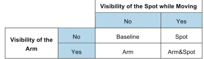
Our intuition is that, by making the motorized projection arm visible, we can help the user to more quickly narrow down the search space for the target. In this user study, we try to identify the relative contributions of being able to see the arm versus a mov-ing spotlight that also guides the user to the target. As mentioned earlier, the PAA provides several cues to guide the user’s search, including the movement of the spot or the direction of the arm. In this laboratory study, we wanted to investigate two of these properties by controlling 1) the visibility of the arm and 2) the visibility of the spot while moving the arm. The four resulting techniques are illustrated on Table 2.
Visibility of the Spot while Moving
No Yes
Visibility of the Arm
No Baseline Spot
Yes Arm Arm&Spot
Table 2: The four guidance techniques we explore in this study. They are or-ganized according to two dimensions: the visibility of the arm and the visibility of the spotlight while moving the arm.
Arm&Spot is the PAA technique: Users can look at the direction of the arm and
fol-low the spotlight to help locate the target. The Arm and Spot techniques derive from PAA by removing one property: Arm does not let users follow the spotlight (which only appears once the final direction of the arm has been reached) while Spot does not let users look at the direction of the arm. The Baseline condition completes our design space so that we can precisely understand the relative contributions of the arm and the spotlight.
5.1. Participants and apparatus
12 participants (6 female) aged from 20 to 38 (M=27.83, SD=4.8) were recruited from our institution. They were compensated for their participation with candy.
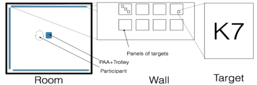
Room. The study was conducted in a room (5x5m2) under standard overhead light-ing condition. The room was equipped with an ARTTrack tracklight-ing system [1] to track the position and orientation of the pico-projector and the user. Figure 1 (b) shows the room.
Targets. Each wall contained 8 paper panels of 20 targets (total = 480) to mimic
the real-world control dials in a control room. We used the three walls to compare three conditions: Targets located in front, behind, or on the side of the participant (Figure 4). Each target was a rectangle (4x3.5 cm2) containing an id of two characters (letter+digit). The font size was 64 to ensure that each participant could easily read them. The distance between targets of 4 cm was superior to the precision of the sys-tem.
Figure 4: Left: map of the room; Right: example of a target part on a panel Techniques. Each of the four tested techniques relies on the same hardware
pre-sented above to avoid possible confounded variables (e.g. inertia of the arm): PAA was installed in the center of the room as shown on Figure 4, with the participant located on its left side. The spotlight has the same shape as a target. We fixed its size to be big enough to be visible from across the room yet not overlap the objects in the vicinity of the target. We also wanted to maintain a small enough size to avoid being overly intrusive while moving. We used the same size and shape of spotlight in all conditions to ensure the same level of difficulty and to avoid to biasing the results. This included correcting for distortion and resizing the spotlight during movement to compensate for the effects of oblique projection angles on the wall. In the Arm condi-tion (spot not visible), the spotlight was switched off during arm movement. In the Spot condition (arm not visible), participants wore basketball dribble glasses that prevented them from looking down at the arm. Finally, participants wore a hat to track head position as well as earphones with a gentle white noise to ensure that they could not hear the sound of the servomotors, which could serve as a hint about rela-tive distance to the target. This was done to prevent confounding factors and to be in accordance with our primary context (control rooms) which is noisy and where users cannot rely on auditory feedback.
5.2. Task and procedure
The task consisted of finding a target as quickly and accurately as possible. Partic-ipants started a trial by pressing button. The arm then moved from its current position
(that of the last target) to highlight the next target. Participants then searched for the target on the three walls by using the arm or the moving spot depending on the condi-tions. As soon as the participants identified the target, they pressed the same button to stop the trial, at which point the spot disappeared and participants orally indicated the ID of the target to the experimenter. Participants could take a short break between each trial and between each block. Participants were videotaped during the experi-ment. After the experiment, they answered a questionnaire and were debriefed via a semi-structured interview.
5.3. Design
We used a within-participants design: each participant tested the four techniques. The order of techniques was counter-balanced using a Latin square design. Partici-pants performed two blocks per technique. Each block contained 25 different target selections (from 460 targets). The location of the targets was randomized in order to appear either on the wall in front of the user, on a lateral wall on his side or on the wall behind him. In summary, the design of this study was: 12 participants × 4 tech-niques (baseline; arm; spot; arm&spot) × 2 blocks × 25 targets = 2400 selections.
6.
Results and Observations
6.1. Completion time analysis
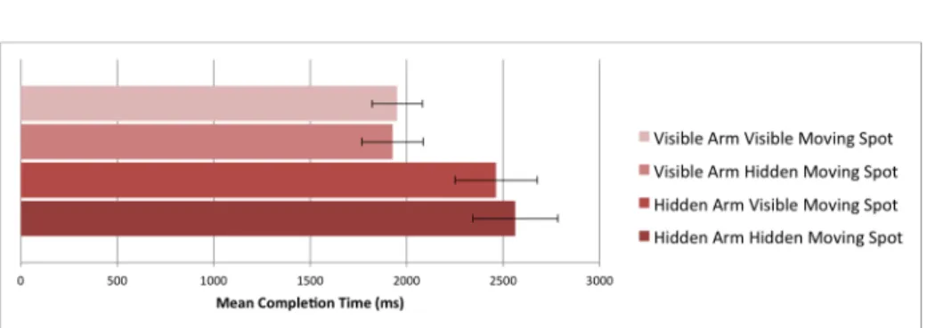
Figure 5: Mean completion time (ms) according to the visibility of the arm and the visibility of the spot while moving.
We assumed the normal distribution of our data (Shapiro-Wilk test) and we used a three way ANOVA which showed a significant effect on completion time of the
loca-tion of the target relative to the initial orientaloca-tion of the user (F2,22=225.17, P<0.001). Post-hoc Tukey tests revealed that this effect is significant for each pair of relative locations between the user and the target. Indeed, the search time was faster if the target was: on the wall in front of the user (1.664 s) rather than on the wall behind him (2.656s, 36.33% improvement); on the front wall rather than on the lateral wall
(2.400 s, 28.58% improvement); and on the lateral wall (2.400 s) rather than on wall behind (2.656s, 11.63% improvement).
ANOVA also showed a significant effect of the visibility of the arm on completion time (F1,11=91.79, P<0.001). Indeed, participants were faster when they could see the arm (1.952 s) than when it was not visible (2.555 s) (see Figure 5).
ANOVA also revealed a significant interaction effect between the visibility of the arm and the relative location of the target from to the initial orientation of the user (F2,22=5.20, P< 0.05) (see Figure 6). Post-hoc Tukey tests confirmed a significant effect for all possible interactions between visibility and relative location, except in two cases: a) when the arm is visible, for lateral (2.079 s) vs. behind (2.261 s), loca-tions; b) for lateral locations when the arm is visible (2.079 s) vs. for front locations when the arm is not visible (1.970 s). For the remaining cases, we found significant decreasing completion time with increasing location distance whether the arm is visi-ble or not.
Finally, there was no significant effect of the visibility of the spotlight while mov-ing (See Figure 5).
Figure 6: Completion time according to the visibility of the arm and the rela-tive location of the target from the orientation of the user (behind, close to (on the lateral wall), and in front of the user).
6.2. Observations and Questionnaire
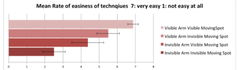
The users rated the ease of the search task for each technique. They preferred the two conditions where the Arm was visible. Then, for each case (Arm visible and Arm not visible), they preferred having a spotlight (Figure 7).
We also made the following observations:
When the arm is visible, users seem to orient themselves faster from the beginning to the end of the search task and stop on the correct direction without exceeding the target. When the arm is hidden and the spot visible, users start moving rapidly but become slower at the end.
Unsurprisingly, when the arm and the spotlight are not visible, users seem to be slower than in any other condition at all stages of the searching task. They also occa-sionally go on the wrong direction, which never happened when both the arm and the spot were visible.
All participants stated that they were aware about the movement of the arm in their peripheral field of view. Some also said they just followed the arm automatically, witout thinking.
The interviews show that users rely on different strategies depending on whether the arm and the moving spot are visible or not. Surprisingly, more than half of the participants (55%) reported that, when the arm was visible, they did not care about the spotlight while it was moving. However, they all tried to follow the spotlight when the arm was not available.
Figure 7: Subjective feeling of easiness for the four conditions (7 corresponds to very easy / 1 to uneasy).
7.
Discussion
Moving Arm. Results confirm our hypothesis that the visibility of the arm
re-duces completion time. However, the results are surprisingly good with a decrease of 27% in average, regardless of the visibility of the moving spotlight. The visibil-ity of the arm is especially useful when the task is complex (i.e the target is not in front of the user). Participants provided several possible explanations: The arm provides an efficient visual cue for localizing the general direction of the targets, presumably because the movement could easily be perceived in the peripheral field of view. This explains why users relied on the arm even when the spotlight was visible. When the arm was visible, participants always oriented their body in the correct direction without overshooting the target. As a result, they did not perform unnecessary movements, which could be time consuming and tiring. This effect could explain the completion time gain. Moreover, several participants mentioned that they were aware of the direction of the arm even without looking at it thanks to the use of their peripheral vision. This is especially useful in scenarios where us-ers have to share their attention (for instance between a paper procedure and veri-fying and activating controls).
Moving spotlight. We expected that the introduction of the moving spotlight
would reduce the completion time. However, our results did not reveal a signifi-cant effect regardless the conditions (visibility of the arm and location of the
tar-gets). Participants explained that the speed of the spotlight was too fast and that they had some difficulties to track it. It results that some participants sometimes tried to anticipate the movement of the spotlight and overshoot the target. As a consequence, the spotlight was not as useful as expected. It would have been pos-sible to use a larger spotlight or reduce its speed. However, both have some draw-backs. Increasing the size of the spotlight can disturb other users (operators in nu-clear plants; consumer in a supermarket) working in the same environment. Reduc-ing the speed of the spotlight would also reduce the speed of the arm, which was not judged too fast. When the moving spotlight was combined with the moving arm, participants explained that they primarily used the arm because they found it more useful.
Finally, in light of the obtained results, it would be interesting to explore sev-eral potential optimizations: depending on the density of the projection area and whether it is shared by other users or not, the speed of the arm and the size of the spot may be controlled dynamically during the movement of the arm. For example, if it is possible to model shared and non-shared spaces, the moving spotlight could be made bigger when moving the arm so as to allow the user to more easily follow-ing it, and to reduce its size in shared areas. Also, the motors could adjust their speed based on the difficulty of following the spotlight on the particular projection surface. In the future when the servomotors and projectors become smaller and the PAA could fit in the hand, we could explore the impact of haptic feedback on lo-calization performance.
8.
Conclusion and Future work
We have designed, implemented and evaluated a novel guidance technique, PAA, which is inspired from the way humans perform in air pointing gestures with their arms to orient each other. Moreover, this technique also relies on a projection system to allow precise indication of the target. Our user study provides two main findings: 1) the moving arm helps users to localize the target especially when the task is complex (i.e. the target is not in front of the users) because users can quick-ly get a raw idea of the direction of the target: the arm is always localized at the same location, in the peripheral vision of the user. In contrast, 2) the moving spot does not provide real benefits because it requires a lot of attention to track it. A challenge would be to design a spotlight easier to track without disturbing other operators and impairing the performance of the arm.
In the present study, we focused on a fully automated PAA: the system con-trols the direction of the arm. As a future work, we plan to investigate scenarios where users (partially) control the arm and how shared control will impact visual search performance. Moreover, we plan to evaluate PAA with multiple operators (and possibly multiple PAAs) to better understand the impact of our system on cognitive load, global awareness and concentration. We also plan to investigate the impact of 3D pointing using the arm vs. 2D pointing using a display to indicate a direction in 3D space.
Acknowledgement
This work is supported by the French ANR/Investissement d’Avenir “Cluster Con-nexion” and by the ÉQUIPEX DigiScope ANR-10-EQPX-0026.
References
1. http://www.ar-tracking.com
2. Butz, A., Schneider, M., & Spassova, M. (2004). SearchLight -- A Lightweight Search Function for Pervasive Environments. In Pervasive’04, Springer 351–356
3. Cauchard, J. R., Fraser, M., Han, T. & Subramanian, S. Steerable Projection: Exploring Alignment in Interactive Mobile Displays. Pers. Ubiquitous Comput.
16, 27–37 (2012).
4. Cosgun, A., Sisbot, E. A. & Christensen, H. I. Evaluation of rotational and directional vibration patterns on a tactile belt for guiding visually impaired people. in Haptics Symposium (HAPTICS), 2014 IEEE 367–370 (2014). 5. Dramas, F., Oriola, B., Katz, B. G., Thorpe, S. J. & Jouffrais, C. Designing an
assistive device for the blind based on object localization and augmented auditory reality. in Proceedings of the 10th international ACM SIGACCESS
conference on Computers and accessibility 263–264 (ACM, 2008).
6. Ehnes, J., & Hirose, M. (2006). Projected Reality - Enhancing Projected Aug-mentations by Dynamically Choosing the Best Among Several Projection Sys-tems. In Virtual Reality Conference, IEEE, 283–284.
7. Ehnes, J., Hirota, K., & Hirose, M. (2004). Projected augmentation - augmented reality using rotatable video projectors. In ISMAR’04, IEEE & ACM, 26-35.
8. Erp, J. B. F. Van, Veen, H. A. H. C. Van, Jansen, C., & Dobbins, T. (2005). Waypoint navigation with a vibrotactile waist belt. ACM Trans. on Applied
Per-ception, 2(2), ACM.
9. Gröhn, M., Lokki, T., & Takala, T. (2005). Comparison of auditory, visual, and audiovisual navigation in a 3D space. ACM Trans. on Applied Perception, 2(4), ACM, 564–570.
10. Harada, S., Takagi, H. & Asakawa, C. On the audio representation of radial direction. in Proceedings of the SIGCHI Conference on Human Factors in
Computing Systems 2779–2788 (ACM, 2011).
11. Harrison, C., Benko, H. & Wilson, A. D. OmniTouch: Wearable Multitouch Interaction Everywhere. in UIST ’11 , ACM, 441–450.
12. Henderson, S. J., & Feiner, S. (2009). Evaluating the benefits of augmented reality for task localization in maintenance of an armored personnel carrier tur-ret. In ISMAR’09, IEEE, 135–144.
13. Henry, P., Krainin, M., Herbst, E., Ren, X., & Fox, D. RGB-D maping:Using kinect-style depth cameras for dense 3d modeling of indoorenvironments.Int. Journal of Robotics Research (IJRR) 2012, IEEE, 31(5):647-663.
14. Ishii, K., Yamamoto, Y., Imai, M. & Nakadai, K. A navigation system using ultrasonic directional speaker with rotating base. In Proceedings of the 2007
15. Jones, B., Sodhi, R., Murdock, M., Mehra, R., Benko, H., Wilson, A., Shapira, L. (2014). RoomAlive: Magical Experiences Enabled by Scalable, Adaptive Projector-camera Units. In UIST’14, ACM, 637–644.
16. Kratz, S., Rohs, M., Reitberger, F., & Moldenhauer, J. (2012). Attjector: an Attention-Following Wearable Projector. In Kinect Workshop at Pervasive’12.
17. Lee, J. C., Dietz, P. H., Maynes-Aminzade, D., Raskar, R. & Hudson, S. E. Automatic Projector Calibration with Embedded Light Sensors. in UIST’04, ACM. 123–126.
18. Lehtinen, V., Oulasvirta, A., Salovaara, A., & Nurmi, P. (2012). Dynamic Tac-tile Guidance for Visual Search Tasks, In UIST’12, ACM, 445–452.
19. Li, M. et al. ProFi: design and evaluation of a product finder in a supermarket scenario. In UbiComp’13 Adjunct, 977–984.
20. Li, M., Arning, K., Sack, O., Park, J., Kim, M.-H., Ziefle, M., & Kobbelt, L. (2013). Evaluation of a Mobile Projector-Based Indoor Navigation Interface. In-teracting with Computers, Oxford Journals.
21. Lindeman, R. W., Sibert, J. L., Mendez-Mendez, E., Patil, S. & Phifer, D. (2005). Effectiveness of directional vibrotactile cuing on a building-clearing task. In CHI’05, ACM, 271–280.
22. Ngo, M. & Spence, C. (2010) Auditory, tactile, and multisensory cues facilitate search for dynamic visual stimuli. Attention, Percep, Psychophys. 72, 1654-1665 23. Ogata, K., Seya, Y., Watanabe, K. & Ifukube, T. Effects of visual cues on the
complicated search task. in 478–485 (ACM).
24. Ota, S., Takegawa, Y., Terada, T. & Tsukamoto, M. (2010) A Method for Wearable Projector Selection that Considers the Viewability of Projected Images. Comput. Entertain. 8, 17:1–17:16.
25. Pinhanez, C. (2001). The Everywhere Displays Projector: A Device to Create. In
UbiComp’01, ACM. 315–331.
26. Pinhanez, C., Kjeldsen, R., Levas, A., Pingali, G., Podlaseck, M., & Sukaviriya, N. (2003). Applications of steerable projector-camera systems. In ICCV
Work-shop on Projector-Camera Systems. IEEE.
27. Pulkki, V. (1997). Virtual Sound Source Positioning Using Vector Base Ampli-tude Panning. Journal Audio Engineering. Sociecty, 45(6), 456–466.
28. Sukthankar, R., Stockton, R. G. & Mullin, M. D. (2001) Smarter presentations: exploiting homography in camera-projector systems. In ICCV’01, (1)247–253. 29. Umlauf, E. J., Piringer, H., Reitmayr, G. & Schmalstieg, D. ARLib: the
augmented library. in Augmented Reality Toolkit, The First IEEE International
Workshop 2 pp.– (2002).
30. Willis, K. D. D., Poupyrev, I., Hudson, S. E. & Mahler, M. (2011) SideBySide: Ad-hoc Multi-user Interaction with Handheld Projectors. in UIST’11, 431–440. 31. Wilson, A., Benko, H., Izadi, S., & Hilliges, O. (2012). Steerable Augmented
Reality with the Beamatron. In UIST’12, ACM, 413–422.
32. Yamano, S., Hamajo, T., Takahashi, S., & Higuchi, K. (2012). EyeSound: sin-gle-modal mobile navigation using directionally annotated music, In Augmented