HAL Id: hal-00865275
https://hal.archives-ouvertes.fr/hal-00865275
Submitted on 7 Oct 2013
HAL is a multi-disciplinary open access
archive for the deposit and dissemination of
sci-entific research documents, whether they are
pub-lished or not. The documents may come from
teaching and research institutions in France or
abroad, or from public or private research centers.
L’archive ouverte pluridisciplinaire HAL, est
destinée au dépôt et à la diffusion de documents
scientifiques de niveau recherche, publiés ou non,
émanant des établissements d’enseignement et de
recherche français ou étrangers, des laboratoires
publics ou privés.
Beamforming-based broadcast scheme for multihop
wireless networks with transmission range adjustment
Ahmed Soua, Walid Ben-Ameur, Hossam Afifi
To cite this version:
Ahmed Soua, Walid Ben-Ameur, Hossam Afifi. Beamforming-based broadcast scheme for multihop
wireless networks with transmission range adjustment. WONS 2013 : The 10th Annual Conference
on Wireless On-Demand Network Systems and Services, Mar 2013, Banff, Canada. pp.107 - 109,
�10.1109/WONS.2013.6578330�. �hal-00865275�
Beamforming-Based Broadcast Scheme for
Multihop Wireless Networks with Transmission
Range Adjustment
Ahmed Soua, Walid Ben-Ameur, and Hossam Afifi
Institut Mines-Telecom, Telecom SudParis, France
Email: [email protected]
Abstract—We investigate here the following fundamental ques-tion - how can we achieve a high reachability while min-imizing the inherent effects of high transmission power for a beamforming-based broadcast scheme in multihop wireless networks? To address this challenge, this paper proposes a fully distributed scheme that allows nodes to set dynamically their transmission range based on their local densities and the distance to the destination. The efficiency of this technique is studied first in a vehicular environment, considered as a particular scheme of a multihop wireless network, and demonstrated in terms of implicated nodes’ratio, power transmission gain and probability of transmission success using real road network-based simulations. Furthermore, the proposal is evaluated using a simplified node distribution scheme, suitable to wireless adhoc networks, and an analytical model is derived to calculate the transmission area. This model allows capturing the propagation shape of the forwarding zone. Extensive simulations confirm the merit of the analytical expressions.
Keywords-Broadcast; Multihop wireless networks; Transmis-sion range adjustment; Vehicular Ad Hoc Networks (VANET); Probability of success; Ratio of implicated nodes; Analytical model; Transmission area.
I. INTRODUCTION
This paper considers the problem of transmission range adjustment techniques over multihop wireless networks. In such networks, radio equiped nodes can communicate with their direct neighbors when they are within the radio trans-mission range. Otherwise, two communicating nodes that are far away from each other may relay on intermediate nodes to relay messages. Over the years, this general concept of multihop wireless networks has manifested itself in numerous forms and names. These include adhoc networks, mobile networks and more recently dynamic networks. Moreover, vehicular adhoc networks (VANETs) are considered as an off-shoot of multihop wireless networks. Indeed, improving the road safety by exchanging relevant information about unsafe driving conditions between vehicles needs practically a multihop dissemination of packets to reach the hazardouz zone. In addition, this information exchange must be done with some guarantees in terms of success probability (reliability), bandwidth and power utilization (efficiency).
On one hand, interference level is considered as the most relevant factor that has a direct impact on network reliabilty and efficiency. This factor is highly dependent on the transmis-sion range used for each communicating node. Indeed, a longer
transmission range in a dense multihop wireless network can lead to a huge amount of interferences between neighbor nodes and a high network overhead. Thus, the network will suffer from inefficiency due to packet collisions and loss.
To alleviate this problem, a transmission range adjustment technique will be a crucial countermeasure to minimize in-terferences and guarantee a high reachability for the multihop transmission operation.
On the other hand, broadcast is still considered as a simple and efficient way to disseminate messages to direct neighbors and other nodes in the vicinity located on a target zone called zone of interest.
In this paper, we are mainly interested in a dissemination process of messages in a multihop wireless environment using transmission range adjustment technique. Dissemination is based here on our previous work [1] where the broadcast operation is based on a directive beamforming system.
The contribution of this paper is a fully distributed range assignment technique for the communicating nodes. We argue that with the combination of our previous work and the transmission range adjustment scheme presented here, our proposal is more efficient in terms of bandwidth and reliability. Another major contribution of this paper is the development of an analytical model providing a very close approximation of the total propagation area obtained by simulations. This model is derived in the case of an uniform node distribution scheme applied on wireless adhoc environment. Simulations confirm the merit of the model.
The reminder of this paper is organized as follows. Section II highlights the related work that addresses the transmission range assignment techniques on multihop wireless networks. A particular focus on vehicular proposals is notable on this part. We present our transmission range adjustment technique in Section III. Section IV is reserved to the validation of our proposed technique using both real street maps and uniform nodes distribution. An analytical model is derived in this section to estimate the propagation shape of the forwarding area. Finally, Section V concludes this paper.
II. RELATED WORK
A number of efforts have been already accomplished to in-vestigate transmission range adjustment techniques for multi-hop wireless networks. Thus, several studies worth our special mention here.
In [2], authors focus on preserving the energy and main-taining the connectivity of the mobile nodes and propose an approach to control the energy used in adhoc networks. Their technique is based on varying the transmission range of the communicating nodes. In fact, this variation depends from the local density of the concerned node: if the node has no neighbors, the transmission range takes the maximum value. Otherwise, it will be equal to the farthest neighbors distance in order to maintain the sufficient number of neighbors. The absence of any analytical model to evaluate their approach constitutes the main weakness of this work.
The concept of power management in wireless adhoc net-works is studied in [3]. Authors proposal is based on a clustering scheme wherein a node adapts its transmit power to establish connectivity with only a limited number of neigh-borhood nodes. Within a cluster, a node may adapt its power transmission to communicate with neighboring nodes or it might use the same power with all nodes located in the cluster. Nevertheless, this technique assumes that each node broadcasts a signaling packet containing its local connectivity table information to construct a global view of the network. This can lead undoubtedly to a huge overhead and a scalability problem since it is not feasible for each node to store the entire global topological information.
In [4], Claudio E. Palazzi and al. proposed the Fast Broadcast (FB) protocol for vehicular networks which uses a distance-based approach with an estimated transmission range. This latter reduces the number of redundant transmissions as well as the hops to be traversed. Their scheme is composed of two phases. The first one, named estimation phase, aims to provide each vehicle with an up-to-date estimation of its forward and backward transmission range. The second one, called broadcast phase, is performed only when a message has to be broadcasted to all cars in the senders area of interest.
Authors in [5] propose a dynamic transmission range assign-ment scheme called DTRA that adjusts a vehicle transmission range based on the estimation of its local traffic density. Their proposition uses an analytical traffic flow model to derive an expression of the local vehicle density which makes vehicles able to adjust the transmission range. This technique is dedicated to highway roads only, and can not be generalized to a planar case.
M.Torento and al. [6] considered a fully distributed strategy to adjust each vehicle node’s transmission power. Their pro-posal, namely D-FPAV, aims to control the channel load by adjusting the transmission power of each vehicle and hence minimize the packet collisions. The optimization is built upon the concept of fairness and the ability of every communicating vehicle to send and receive alert messages in a fair way.
Another effort made by B.Rawat and al. [7] focuses on dynamic adaptation of joint transmission power and con-tention window considering vehicle densities and network traffic conditions. Indeed, their proposed algorithm adapts the transmission power based on estimated traffic density. For the adaptation of QoS parameters (e.g. contention window), the prioritization is assigned according to the relevance of the message and time delay requirements. To this end, they incorporated the enhanced distributed channel access (EDCA)
mechanism from the IEEE 802.11e standard. Nevertheless, simulations were restricted only to highway scenarios which are not enough to generalize these results.
Finally, in [8], authors address inter vehicle communication with stop and go waves and carried out an algorithm to adjust the transmission range of vehicles with the aim to achieve a better reliability. They study communication on highways with single-hop periodic broadcast. Their proposed scheme adjusts the transmission range by taking into account the variance coefficient of vehicles’ spacing. Based on NS2 simulations, they prove that their technique realizes good packet reception rates.
We believe that these algorithms are too complex for our context and the purpose of multihop wireless applications which require a rapid relaying of information among nodes. In addition, none of the above related works try to investigate their techniques in different multihop wireless networks sce-narios and derive analytical models to study the performances of their systems. That’s why, we propose here a simple and efficient transmission range adjustment technique devoted to a broadcast multihop scenario. Our approach is based on local densities of nodes and a parameter called angular coefficient which has to be shared with participating nodes. Our technique is totally distributed and does not depend on very precise positionning systems. The efficiency of our proposal is con-firmed in two diffrent multihop node distribution scenarios. Furthermore, an analytical model is derived to estimate the proportion of implicated nodes in the case of an uniform node distribution.
III. PROPOSEDTECHNIQUE
In this section, we describe our proposed transmission range adjustment’s mechanism in a multihop wireless broadcasting scheme.
A. Broadcasting scheme
This paper, as mentioned before, is an improvement of our works [1] and [9]. In the first work, we proposed a beamforming-based broadcast technique based on two geo-graphic information: the direction to the destination and the beamforming angle θ. In [9] we derive an analytical framework in case of θ= 0 to study the network performances of a linear propagation in VANETs. We refer the reader to Section 3 of [1] for a fully explanation. Hereafter a short summary of this proposal is reproduced.
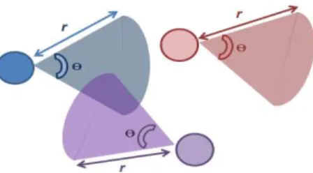
We envision a multihop wireless environment where nodes are able to determine their geographic position using a Global Positioning System (GPS) receiver. In our context, we assume that all nodes are equiped with directional antennas. In our modeling approach, the directional antenna is modeled as a circular sector with an angle θ and a radius equal to the transmission/reception range r. As shown by Fig.1, the directional antenna gain is within the angle θ, which represents the beamwidth of the antenna. Hence, the gain outside the sector limited by θ is approximated to zero.
Fig. 1: Directional Antenna Model
Furthermore, we assume that nodes exchange two types of messages: beacons and event driven-driven messages. When the former aims at improving node awareness of surrounding environment by exchanging information about position, veloc-ity, direction, etc. The latter is triggered when a node needs to broadcast a message to a specefic geographic zone.
Hence, upon receiving an intermediate packet, each node must decide whether this packet should be forwarded and where to forward it. To this end, nodes that receive an intermediate message will broadcast it on their turn unless they have receive it before, or unless they are the destination. The system ends broadcasting when there are no more relays to broadcast or the message reachs the destination. For the second issue (the forwarding direction), each relaying node points its directional beam toward the destination’s position and makes an angle θ2with each side of the central axe linking the relaying node and the destination. In this case, only nodes positioned in the zone covered by the directional beam (sector limited by θ) will receive the message as shown by Fig.2.
It is worthnoting that the beamforming angle θ is fixed from the beginning of transmission operation and it is the same for all the participating nodes. As mentioned before, each communicating node is supposed to know or to guess the direction of its destination in order to determine the direction of the transmitted beams. This is done using GPS receivers installed on each node.
The success or failure of the transmission is strongly depen-dent on the density of neighbour nodes λ and the beamwidth of the directional antenna. In fact, this angle has a great effect on the overall performance of our proposal. A very wide angle provides some insurance that the message would reach its destination. However, a larger set of nodes is involved and the performance of the overall relaying system may shrink down. On the other hand, a small beamforming angle prevents waste of bandwidth but may lead to more transmission failures.
B. Transmission Range Adjustment Technique
In [1], we used a fixed transmission range for all the participating nodes. Here, the proposed scheme adjusts the transmission range for each node by multiplying the original range with a coefficient called adjustment coefficient. This coefficient is the same for all nodes. In fact, only the sender (the node who originates the alert message) computes this coefficient and then relay nodes, participating in the broadcast operation, will calculate their transmission range based on this parameter.
Fig. 2: Directional beamforming broadcast scheme
Assume that the first node (the originator of the message) broadcasts the message with an angle θ and a radius r1. This
latter is a fixed parameter. The distance between the source and the destination is denoted by d1. Therefore, the adjustment
coefficient is given by: C= r1 d1.
This parameter has to be added to alert messages to allow other relays compute their adjusted transmission range based on C. Indeed, we denote nodei a relay node indexed by i.
This relay is distant from the destination by di. The adjusted
transmission range for nodei, namely (ri) can be computed
using the following rule:
ri= C ∗ di (1)
We notice that the above equation can lead to very little transmission range (approximated to 0) when the relay vehicle becomes very close to the destination node (di∼0). This fact
can easily stop the propagation of the message and hence the rest of the participating nodes will not be reachable by the propagated information.
To alleviate this challenge, the algorithm defines a minimum transmission range value (rmin) considered as a a minimum
threshold. Thus, all nodes have to maintain a transmission radius greater or equal to this value. In fact, rmin can be
seen as the transmission range that guarantees the existance of at least one neighboring node in the vicinity of each forwarding node. rmin depends on the local densities of
nodes (λi) computed by each relaying nodei in the network.
As demonstrated in [10], the nodei’s local density can be
expressed as follows: λi= Ci onnectivity π ∗ r2 i (2)
where Connectivityi refers to the nodei’s connectivity i.e.,
the number of its direct neighbors. This latter can be easily computed using the beaconing mechanism.
Thereby, rmini can be expressed as(ri
min)2∗θ2∗λi≈1. Consequently, we obtain ri min ≈ q ( 2 θ∗λi). Thereby, Eq.1
can be rewritten as follows :
ri= max(rmini , C ∗ di) (3)
This new expression of ri guarantees a none-zero dynamic
transmission range for the communicating nodes and therefore reachability for distant neighbors.
IV. PERFORMANCESEVALUATION
In this section, we first evaluate the performance of our proposed transmission range adjustment technique in the case of a vehicular network. Then, we compare it to our previous work (i.e. A fixed transmission range for the beamforming-based broadcast scheme)[1]. To this end, we developed our Matlab [11] [13] based simulation tool and performed simula-tion with real street maps. We focus on the impact of this technique on bandwidth and power utilization. In addition, we study the performances of our proposal in terms of probabilty of success (i.e the probability of the alert message to reach the destination). Findings corroborate the efficiency of our optimization compared to [1] and its improvement of bandwidth utilization.
Another major contribution of this paper is the development of an analytical model to estimate the transmission area of the forwarding process in the case of a simplified multihop nodes distribution. Finally, the model is compared to simulations.
A. Results using real road network
To make the proposed scheme tractable, we make the following assumptions:
1) We asssume an ideal MAC layer without contention, collision, or node mobility.
2) All nodes have the initial transmission range equal to 200 m.
3) The number of vehicles was varied from from 250 to 1000.
4) We vary the beamforming angle θ from 22.5◦ to135◦.
We assume that the vehicles are distributed on each lane of the streets according to a Poisson process of intensity λ= 0.04. In other words, the distance between two consecu-tive vehicles follows an exponential distribution. The average distance between two vehicles is λ1. This assumption is based on some traffic studies that have proved that the inter-vehicle spacing on a highway can be modeled by an exponential distribution [12].
Assumption related to the nodes mobility (1), can safely be adopted since during rush hour urban traffic the velocity of vehicles is limited and the vehicles density is very important. Indeed, the speed of nodes in such case, compared to the duration of wireless transmission, is very small and therefore we can assume that the node positions and connectivity do not change significantly from a broadcast operation to another.
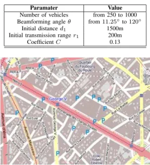
Furthermore, we use the framework OpenStreetMap for Matlab [13] to construct a real road topology. Indeed, we have chosen the ”Champs- ´Elys´ees” avenue to test our optimized broadcast protocol. The map (see Fig.4), centered at latitude: 2.303◦ and longitude:48.8712◦, has 10 intersections and 17
road segments. The main street (Champs- ´Elys´ees) is composed of 4 lanes in each direction. All lanes are 2 Km in length. The total width of the Champs- ´Elys´ees street is equal to 30 meters. The broadcast process is triggered along this street. Details of the simulation setup parameters are listed in TABLE I.
Two main scenarios are considered here: Fixed and dynamic transmission ranges are used in the beamforming broadcast process. Notice that the initial transmission range r1 used
TABLE I: Simulation Configurations
Paramater Value Number of vehicles from 250 to 1000 Beamforming angle θ from 11.25◦to 120◦
Initial distance d1 1500m
Initial transmission range r1 200m
Coefficient C 0.13
Fig. 4: Road topology
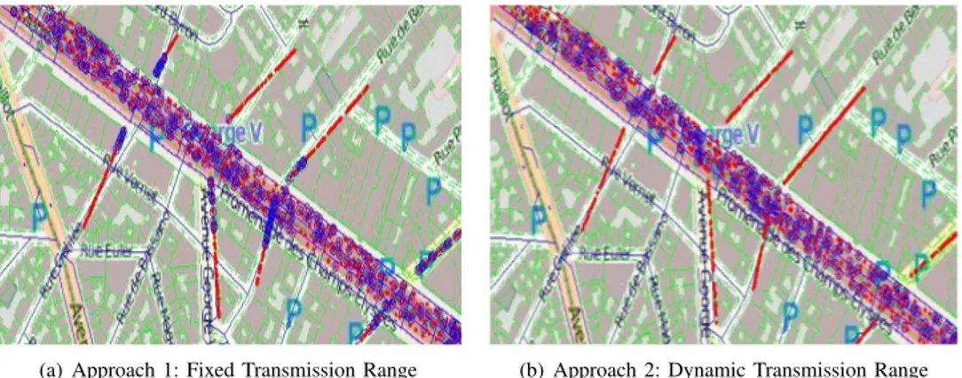
in the dynamic approach is supposed to be equal to the fixed radius used in the fixed technique. Figures 3(a) and 3(b) provide a comparison of the snapshot of the relaying nodes involved in the transmission process for both the two approaches. The maps represent a zoom of one region of the Champs- ´Elys´ees street. Circled nodes denote the vehicles implicated in the forwarding operation. We observe that, with the dynamic transmission range, nodes located on the side streets are not participating in the broadcast process contrary to the fixed transmission radius technique. Furthermore, adjusted radius technique reduces the number of implicated vehicles in the Champs- ´Elys´ees main street compared to the fixed range method. Hence, we can conclude that the adjustment of the transmission radius significantly reduces the number of implicated nodes.
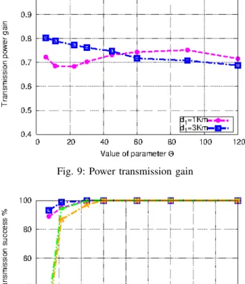
Figure 5 depicts the gain in power transmission when varying the angle θ and the distance between the source and the destination. This gain is computed as follows:
Gpower =
Pf−P d
Pf
(4) where Pf and Pd refer to the power used by all participating
nodes in case of fixed and dynamic transmission radius re-spectively. In the case of directional antenna, the transmission power is proportional to the square of the transmission range r. Thus, Pfand Pdcan be respectively expressed as β ∗m1∗r12
and β ∗Pm2j=1r2j. Hence, Eq.4 can be simplified as follows:
Gpower = 1 −
Pm2 j=1rj2
m1∗r12
(5) where m1and m2are respectively the implicated nodes in the
broadcasting operation with fixed and dynamic transmission ranges. From Figure 5 we notice that our technique maintains for all cases (n= 500 and n = 750) a gain greater than 55%. We remark also that even using wide values of θ, the power
(a) Approach 1: Fixed Transmission Range (b) Approach 2: Dynamic Transmission Range
Fig. 3: Implicated Nodes in the forwarding process for the 2 approachs
Fig. 5: Power transmission gain
gain stills important. This leads obviously to less interferences and packet loss. Thus, our adjustment technique excells in power preservation compared to a fixed transmission range approach.
In Figure 6, we investigate the proportion of implicated nodes in the beamforming-based broadcast operation when varying the density of vehicles. The top two lines are for nodes using a fixed transmission radius with variation of the density of nodes from 750 to 500. The bottom two lines depict the effect of adjusting the transmission range for the same values of nodes densities. When nodes transmit with a high beamforming angle, we observe an increase in the ratio of implicated nodes for the two scenarios. We also notice that transmitting messages within a limited beamwidth as well as with an adjusted transmission range reduces severally the number of nodes having to relay the message compared to a fixed transmission range approach.
In Figure 7, we illustrate the variation of the probability of transmission success as a function of θ and the density of nodes. The top two lines show the success probability for 750 and 500 vehicles using a fixed transmission range. Whereas the bottom lines show this metric for a dynamic radius scenario for the same values of nodes densities. Obviously, the probability of transmission success increases as the density of nodes increases leading to less fragmentation in the network.
Fig. 6: Ratio of implicated nodes: Comparison overview
Fig. 7: Probability of transmission success: Comparison overview
Although the transmission range adjustment technique results in little lower performances, one can see clearly that the curves are close.
These findings undoubtedly prove that our proposed tech-nique ensures a high ratio of reachability and improves at the same time the power utilization.
(a) Approach 1: Fixed Transmis-sion Range
(b) Approach 2: Dynamic Trans-mission Range
Fig. 8: Implicated Nodes in the transmissions for the 2 approachs
B. Results using an uniform nodes distribution
In this part, we suppose that the participating nodes are randomly positioned in a rectangular area of3500 × 2000m2
according to a poisson process of density λ in spite of using real street map. Thus, λ can be obtained by dividing the total number of nodes by the area of the rectangle. All assumptions given in the previous part are still maintained here. The distance d1 represents how far the message transmission is
expected to go ahead. It can be a distance threshold imposed by upper applications.
First, we evaluate the performances of our proposal in this new scheme of nodes distribution and then we provide an analytical model to estimate the area of messages transmission (i.e the messages’s forwarding zone).
1) Simulation Results:
Figure 8 presents a comparison of the snapshot of the relaying nodes participating in the transmission operation for both the two approaches. We see again that the adjustment of the transmission radius significantly reduces the number of implicated nodes.
In Figure 9, we show the gain in power transmission, calculated using Eq.4, when varying the beamforming angle θ and the distance d1. We observe that transmission range
adjustment technique allows a good gain in power utilization such as the previous node distribution case. In addition, the values for the two scenarios are close.
Figure 10 depicts the variation of the probability of trans-mission success considering diffrents values of distance d1. We
notice that the proposed technique ensures a high reachability even in the case of a little density of nodes. This observation corroborates the robustness of our scheme.
2) Analytical model for the transmission area:
We provide in this section an analytical model to esti-mate the area of messages transmission (i.e the messagess forwarding zone). The communicating nodes are uniformaly positioned in a rectangular area. Each node broadcasts the message according to an angle θ within a radius r propor-tional to the distance d as indicated by Eq.1. Therefore, the propagation shape of the forwarding area can be approximated by Figure 11. The transmission zone can be approximated by
Fig. 9: Power transmission gain
Fig. 10: Probability of transmission success: Comparison overview
a set of triangles having the destination node as a common vertex. Each two consecutive triangles have a common vertex in addition to the destination. The vertex of a each triangle T r(i), whose first vertex is located at a distance di of the
destination, is obtained by considering that there is a mobile node transmitting according to an angle θ and within a transmission range ri proportional to the distance di (see
Eq.1). This figure has to be considered as an approximation of the actual area of transmission since we have added the suppositon of the existance of a minimum transmission range in broadcasting operation.
Proposition 1. Assuming that C = r1
d1 ≪ cos( θ
2), the total
area of the transmissionStotal can be expressed as :
Stotal≈ 1 2d 2 1tan( θ 2)(1 − e ( −2π tan(θ2))) (6)
where d1 is the distance between the first sender and the
destination. Proof:
From Figure 12 and as we have mentioned before, the radius of transmission riis proportional to the distance di(see Eq.1).
Fig. 11: Forwarding shape
Fig. 12: Similar triangles
broadcast the message according to an angle θ. Hence, all triangles T ri are similar. Let γ = didi
−1
be the coefficient of this similarity. γ is called scale factor.
We give a simple expression of γ.
γ= d2 d1 = s 1 +r 2 1−2r1d1cos (θ2) d2 1 (7) In Eq.7, r 2 1−2r1d1cos (θ 2) d2 1 ≈ 0(d1 ≫ r1), then γ can be expressed as follows: γ ≈1 +1 2( r2 1−2r1d1cos (θ2) d2 1 ) ≈ 1 −r1cos ( θ 2) d1 (8) We denote α the angle dABC. Then, the total number of triangles T ri situated on the half plane containing the source
is given by : N ≈ π α (9) where α ≈sin(α) ≈ r1sin( θ 2) d2 ≈ r1sin( θ 2) γd1 (10) The elementary surface of each triangle T ri, denoted as Si,
can be computed as follows : Si=12ridisinθ2. The similarity
between triangles T riimplies that Si= γ2iS1. Then, the total
area of transmission can be given by:
Stot= 2 N X 1 Si≈2 N X 1 γ2iS1≈2S1 N X 1 γ2i≈2S11 − γ 2N 1 − γ2 (11) Using the fact that xy = eyLn(x) and the assumption r1 d1 ≪cos( θ 2), γ2N can be expressed as γ2N ≈ e2N Ln(γ) ≈ e2N Ln(1− r1 cos (θ2) d1 ) ≈ eN( −2r1 cosθ2 d1 ) (12)
Eq.12 can be more simplified by using Eq.9, Eq.10 and the fact that γ ≪1. We obtain then γ2N ≈e(−2π cotθ
2)
By using formula (8) and remplacing γ2N by its expression, Eq.11 can be expressed as
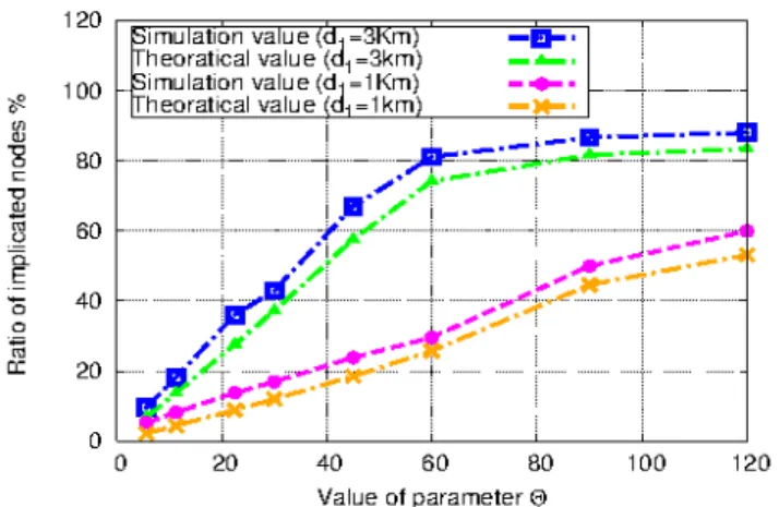
Fig. 13: Comparison between the theoretical and practical values of the implicated nodes
Stot≈2S1(1 − e (−2π cotθ 2) 2r1cosθ 2 d1 ) ≈ 2S1( d1(1 − e−2π cot θ 2) 2r1cosθ2 ) (13) Hence, remplacing S1 by its expression, Eq.13 becomes : Stot= 21 2r1d1sin ( θ 2)( d1(1 − e−2πcot θ 2) 2r1cosθ 2 ) = 1 2d 2 1tan θ 2(1 − e ( −2π tanθ2)) (14)
Note that the area of transmission does not depend on the initial radius r1(under the assumption d1r1 ≪cos (θ
2)).
With the above analytical investigation, simulations are presented hereafter. We aim to evaluate the accuracy of our analytical model by comparing it to simulation results. Note that, the comparison analysis is presented here in term of the ratio of implicated nodes.
For that purpose, we present in Figure 13 a comparison of the implicated nodes’ ratio for both simulation and theoretical results. We consider, for the simulation scenario, a total number of communicating nodes equal to 3000.
Figure 13 depicts that the gap between the simulation and the theoretical curves is very tight. Thus, our proposed analytical model provides a good approximation of the real transmission shape.
V. CONCLUSION
We have considered the problem of transmission range adjustment in a multihop wireless network context. An opti-mized technique devoted to the adaptation of the transmission radius based on nodes’ local densities and the distance to the destination was proposed. Conducted simulations for vehicular networks using real street maps corroborate the efficiency of our proposed scheme in terms of ratio of implicated nodes, power transmission gain and probability of transmission success. We have also evaluated our approach in the case of an uniform node distribution and findings confirm the previous results. As a major contribution as well, we have derived an analytical model that provides an estimation of the transmission area. Simulation results match very well the mathematical expressions.
REFERENCES
[1] A.Soua, W.Ben-Ameur, H.Afifi, Broadcast-based Directional Routing in
Vehicular Ad-Hoc Networks, IEEE/IFIP Wireless and Mobile Networking Conference (WMNC), Sept. 2012.
[2] F. Tolba, D. Magoni, W.L Jin, P. Lorenz, Energy saving and connectivity
tradeoff by adpative transmission range in 802.11g MANETs, IEEE Inter-national Conference on Wireless and Mobile Communications (ICWMC), pp. 45-50, 2006.
[3] T. Ebatt, S. Krihnamurthy, D. Connors, S. Dao, Poxer Management for
Throughput Enhancement in Wireless Adhoc Networks, IEEE Interna-tional Conference on Communications (ICC), pp. 1506-1513, 2000. [4] C. Palazzi, S. Ferretti, M. Roccetti, G. Pau, and M. Gerla, How Do You
Quickly Choreograph Inter-Vehicular Communications? A Fast Vehicle-to-Vehicle MultiHop Broadcast Algorithm, IEEE CCNC International Workshop on Networking Issues in Multimedia Entertainment, 2007. [5] M. Artimy, Local Density Estimation and Dynamic Transmission-Range
Assignment in Vehicular Ad Hoc Networks, IEEE Transactions on Intel-ligent Transportation Systems, vol. 8, pp. 400-412, Sept. 2007. [6] M. Torrent-Moreno, P. Santi, H. Hartenstein, Distributed Fair Transmit
Power Adjustment for Vehicular Ad Hoc Networks, IEEE Communications Society on Sensor and Ad Hoc Communications and Networks, Sept. 2006.
[7] D.B. Rawat, G. Yan, D.C. Popescu, M.C. Weigle, S.Olariu, Dynamic
Adaptation of Joint Transmission Power and Contention Window in VANET, IEEE Vehicular Technology Conference Fall (VTC-Fall), Sept. 2009.
[8] R. Chen, H. Yang, W.L Jin, A. Regan, Dynamic transmission range in
inter-vehicle communication with stop-and-go traffic, IEEE Intelligent Vehicles Symposium (IV), pp. 1166-1171, June. 2010.
[9] A.Soua, W.Ben-Ameur, H.Afifi, Analysis of Information Relay
Process-ing in Inter-Vehicle Communication: A novel visit, IEEE International Conference on Wireless and Mobile Computing, Networking and Com-munications (WiMob), Oct. 2012.
[10] Z.Li, Y.Zhao, Y.Cui, D.Xiang, Density Adaptive Routing Protocol for
Large-Scale Ad Hoc Networks , IEEE Wireless Communications and Networking Conference (WCNC), March. 2008.
[11] www.mathworks.fr/products/matlab.
[12] N. Wisitpongphan, F. Bai, P. Mudalige, V. K. Sadekar, and O. K. Tonguz,
Routing in Sparse Vehicular Ad Hoc Wireless Networks, IEEE Journal on Selected Areas in Communications, vol. 25, no. 8, pp. 1538-1556, Oct. 2007.
[13] http://www.mathworks.com/matlabcentral/fileexchange/35819-openstreetmap-functions.