HAL Id: hal-00854027
https://hal.archives-ouvertes.fr/hal-00854027
Submitted on 16 Oct 2013
HAL is a multi-disciplinary open access
archive for the deposit and dissemination of
sci-entific research documents, whether they are
pub-lished or not. The documents may come from
teaching and research institutions in France or
abroad, or from public or private research centers.
L’archive ouverte pluridisciplinaire HAL, est
destinée au dépôt et à la diffusion de documents
scientifiques de niveau recherche, publiés ou non,
émanant des établissements d’enseignement et de
recherche français ou étrangers, des laboratoires
publics ou privés.
Low loss microstructured chalcogenide fibers for large
non linear effects at 1995 nm.
Johann Troles, Quentin Coulombier, G. Canat, M. Duhant, W. Renard,
Perrine Toupin, Laurent Calvez, Gilles Renversez, Frédéric Smektala,
Mohamed El Amraoui, et al.
To cite this version:
Johann Troles, Quentin Coulombier, G. Canat, M. Duhant, W. Renard, et al.. Low loss
microstruc-tured chalcogenide fibers for large non linear effects at 1995 nm.. Optics Express, Optical
Soci-ety of America - OSA Publishing, 2010, Focus Issue: Chalcogenide Glass, 18 (25), pp.26647-26654.
�10.1364/OE.18.026647�. �hal-00854027�
Low loss microstructured chalcogenide fibers for
large non linear effects at 1995 nm
J. Troles1,*, Q Coulombier1, G. Canat2, M. Duhant2, W. Renard2 P. Toupin1, L. Calvez1, G. Renversez3, F. Smektala4, M. El Amraoui4, J. L. Adam1, T. Chartier5, D. Mechin6, L.
Brilland6
1 Equipe Verres et Céramiques, UMR-CNRS 6226, Sciences Chimiques de Rennes, Université de Rennes I, 35042
Rennes Cedex, France
2 ONERA, Chemin de la hunière, 91761, Palaiseau Cedex, France
3 Institut Fresnel, UMR CNRS 6133, Université d'Aix-Marseille, 13397 Marseille, France 4
Laboratoire interdisciplinaire Carnot de Bourgogne, ICB UMR CNRS 5209 -Université de Bourgogne, 9 Av. A. Savary, BP 47870, 21078 Dijon cedex, France
5 Laboratoire Foton, UMR CNRS 6082, ENSSAT, 22300 Lannion, France
6 PERFOS, Plate-Forme d’Etude et de Recherches sur les Fibres Optiques Spéciales, 11, rue Louis de Broglie,
22300 Lannion, France *johann.troles@univ-rennes1.fr
Abstract: Microstructured optical fibers (MOFs) are traditionally prepared
using the stack and draw technique. In order to avoid the interfaces problems observed in chalcogenide glasses, we have developed a new casting method to prepare the chalcogenide preform. This method allows to reach optical losses around 0.4 dB/m at 1.55 µm and less than 0.05 dB/m in the mid IR. Various As38Se62 chalcogenide microstructured fibers have been
prepared in order to combine large non linear index of these glasses with the mode control offered by MOF structures. Small core fibers have been drawn to enhance the non linearities. In one of these, three Stokes order have been generated by Raman scattering in a suspended core MOF pumped at 1995 nm.
©2010 Optical Society of America
OCIS codes: (060.2390) Fiber optics, infrared; (160.2750) Glass and other amorphous
materials; (060.2270) Fiber characterization; (060.4370) Nonlinear optics, fibers; (060.4005) Microstructured fibers
References and links
1. J. M. Harbold, F. O. Ilday, F. W. Wise, J. S. Sanghera, V. Q. Nguyen, L. B. Shaw, and I. D. Aggarwal, “Highly nonlinear As-S-Se glasses for all-optical switching,” Opt. Lett. 27(2), 119–121 (2002).
2. P. Houizot, F. Smektala, V. Couderc, J. Troles, and L. Grossard, “Selenide glass single mode optical fiber for nonlinear optics,” Opt. Mater. 29(6), 651–656 (2007).
3. P. Kaiser, E. A. J. Marcatili, and S. E. Miller, “A new optical fiber,” Bell Syst. Tech. J. 52, 265–269 (1973). 4. L. Fu, M. Rochette, V. Ta’eed, D. Moss, and B. Eggleton, “Investigation of self-phase modulation based optical
regeneration in single mode As2Se3 chalcogenide glass fiber,” Opt. Express 13(19), 7637–7644 (2005).
5. D. I. Yeom, E. C. Mägi, M. R. E. Lamont, M. A. F. Roelens, L. Fu, and B. J. Eggleton, “Low-threshold supercontinuum generation in highly nonlinear chalcogenide nanowires,” Opt. Lett. 33(7), 660–662 (2008). 6. M. El-Amraoui, J. Fatome, J. C. Jules, B. Kibler, G. Gadret, C. Fortier, F. Smektala, I. Skripatchev, C. F.
Polacchini, Y. Messaddeq, J. Troles, L. Brilland, M. Szpulak, and G. Renversez, “Strong infrared spectral broadening in low-loss As-S chalcogenide suspended core microstructured optical fibers,” Opt. Express 18(5), 4547–4556 (2010).
7. J. S. Sanghera, I. D. Aggarwal, L. B. Shaw, C. M. Florea, P. Pureza, V. Q. Nguyen, and F. Kung, “Nonlinear properties of chalcogenide glass fibers,” Journal of Optoelectronics and Advanced Materials 8, 2148–2155 (2006).
8. O. P. Kulkarni, C. Xia, D. J. Lee, M. Kumar, A. Kuditcher, M. N. Islam, F. L. Terry, M. J. Freeman, B. G. Aitken, S. C. Currie, J. E. McCarthy, M. L. Powley, and D. A. Nolan, “Third order cascaded Raman wavelength shifting in chalcogenide fibers and determination of Raman gain coefficient,” Opt. Express 14(17), 7924–7930 (2006).
9. P. A. Thielen, L. B. Shaw, P. C. Pureza, V. Q. Nguyen, J. S. Sanghera, and I. D. Aggarwal, “Small-core As-Se fiber for Raman amplification,” Opt. Lett. 28(16), 1406–1408 (2003).
#134005 - $15.00 USD Received 31 Aug 2010; revised 15 Sep 2010; accepted 18 Sep 2010; published 6 Dec 2010
10. A. Tuniz, G. Brawley, D. J. Moss, and B. J. Eggleton, “Two-photon absorption effects on Raman gain in single mode As2Se3 chalcogenide glass fiber,” Opt. Express 16(22), 18524–18534 (2008).
11. P. Houizot, C. Boussard-Plédel, A. J. Faber, L. K. Cheng, B. Bureau, P. A. Van Nijnatten, W. L. M. Gielesen, J. Pereira do Carmo, and J. Lucas, “Infrared single mode chalcogenide glass fiber for space,” Opt. Express 15(19), 12529–12538 (2007).
12. T. M. Monro, Y. D. West, D. W. Hewak, N. G. R. Broderick, and D. J. Richardson, “Chalcogenide holey fibres,” Electron. Lett. 36(24), 1998–2000 (2000).
13. L. Brilland, F. Smektala, G. Renversez, T. Chartier, J. Troles, T. Nguyen, N. Traynor, and A. Monteville, “Fabrication of complex structures of Holey Fibers in Chalcogenide glass,” Opt. Express 14(3), 1280–1285 (2006).
14. F. Désévédavy, G. Renversez, L. Brilland, P. Houizot, J. Troles, Q. Coulombier, F. Smektala, N. Traynor, and J.-L. Adam, “Small-core chalcogenide microstructured fibers for the infrared,” Appl. Opt. 47(32), 6014–6021 (2008).
15. J. C. Knight, T. A. Birks, P. S. J. Russell, and D. M. Atkin, “All-silica single-mode optical fiber with photonic crystal cladding,” Opt. Lett. 21(19), 1547–1549 (1996).
16. L. Brilland, J. Troles, P. Houizot, F. Desevedavy, Q. Coulombier, G. Renversez, T. Chartier, T. N. Nguyen, J.-L. Adam, and N. Traynor, “Interfaces impact on the transmission of chalcogenides photonic crystal fibres (Glass and Ceramic Materials for Photonics),” J. Ceram. Soc. Jpn. 116(1358), 1024–1027 (2008).
17. Q. Coulombier, L. Brilland, P. Houizot, T. Chartier, T. N. N’guyen, F. Smektala, G. Renversez, A. Monteville, D. Méchin, T. Pain, H. Orain, J. C. Sangleboeuf, and J. Trolès, “Casting method for producing low-loss chalcogenide microstructured optical fibers,” Opt. Express 18(9), 9107–9112 (2010).
18. J. A. Savage, and S. Nielsen, “Chalcogenide glasses transmitting in the infrared between 1 and 20 µm - a state of the art review,” Infrared Phys. 5(4), 195–204 (1965).
19. D. Lezal, J. Pedlikova, J. Gurovic, and R. Vogt, “The preparation of chalcogenide glasses in chlorine reactive atmosphere,” Ceramics(Praha) 40, 55–59 (1996).
20. M. F. Churbanov, I. V. Scripachev, G. E. Snopatin, V. S. Shiryaev, and V. G. Plotnichenko, “High purity glasses based on arsenic chalcogenides,” J. Opt. Adv. Mat 3, 341–349 (2001).
21. G. Snopatin, V. Shiryaev, V. Plotnichenko, E. Dianov, and M. Churbanov, “High-purity chalcogenide glasses for fiber optics,” Inorg. Mater. 45(13), 1439–1460 (2009).
22. G. Renversez, F. Bordas, and B. T. Kuhlmey, “Second mode transition in microstructured optical fibers: determination of the critical geometrical parameter and study of the matrix refractive index and effects of cladding size,” Opt. Lett. 30(11), 1264–1266 (2005).
23. F. Désévédavy, G. Renversez, J. Troles, L. Brilland, P. Houizot, Q. Coulombier, F. Smektala, N. Traynor, and J. L. Adam, “Te-As-Se glass microstructured optical fiber for the middle infrared,” Appl. Opt. 48(19), 3860–3865 (2009).
24. M. Jiang, and P. Tayebati, “Stable 10 ns, kilowatt peak-power pulse generation from a gain-switched Tm-doped fiber laser,” Opt. Lett. 32(13), 1797–1799 (2007).
1. Introduction
Chalcogenide glasses are known for their large transparency window and their large non linear optical properties. Indeed, they can be transparent from the visible region up to the infrared, up to 12 to 15 µm, depending on their composition. Another remarkable property of chalcogenide glasses is their strong optical non linearity. The non linear refractive index of sulfur based glasses is over 100 times larger than silica one. The non linear index of selenium and tellurium based glasses can be more than 1000 times larger than silica one [1,2]. Silica microstructured optical fibers (MOFs) were fabricated as soon as 1973 [3] while chalcogenide ones were drawn only in the last decade. The manufacturing of small core fibers (diameter smaller than 5 µm) can be of great interest to enhance the non linear optical properties for telecom applications such as signal regeneration [4], for supercontinuum generation [5–7] and conversion to the mid infrared using Raman shifting [8–10]. Conversely power transportation and optical countermeasures in the 3-5 and the 8-12 µm windows require large effective mode area and single mode fibers can be designed to permit the propagation of high power Gaussian laser beams. Single mode fiber can be also used for spatial interferometery in the 4-12 infrared windows [11]. The first chalcogenide MOF, was made in 2000, but no light propagation was demonstrated [12]. Since then, chalcogenide MOF, with light guidance [7, 13] and small mode area [14] were obtained. The usual method to prepare MOFs is the stack and draw technique. This method comes from the silica technology [15] but optical losses of the chalcogenide MOFs produced using it were still larger than the material losses whatever the wavelength [13, 14]. In 2008, we have demonstrated that most of the optical losses were
#134005 - $15.00 USD Received 31 Aug 2010; revised 15 Sep 2010; accepted 18 Sep 2010; published 6 Dec 2010
due to debased interfaces between capillaries [16]. We concluded that the stack and draw method was not well suited to fabricate low loss chalcogenide MOFs. In a recent paper, a moulding method was used to realize the preform [17]. This method permits to avoid all the capillary interfaces encountered in the stack and draw method. It reduces considerably the propagation losses. In the present study, optimized glass synthesis and thermal processing during the moulding operation lead to improved transmission compared to ones described in reference [17]. Large core and small core low loss MOFs have been prepared with the As38Se62 glass composition. As an example of strong non linear effect in IR, Raman shift
wavelength up to 2330nm have been demonstrated by pumping an As38Se62 MOF at 1995 nm
in the nanosecond regime.
2. Low loss chalcogenide microstructured optical fibers
2.1 Glass rod and fiber preparation
As38Se62 glass rods are previously fabricated and purified with the usual sealed silica tube
method [18]. The As-Se glass is purified thanks to several synthesis steps using a small amount of oxygen and hydrogen getters (Al and TeCl4, respectively) [19]. At first, a glass rod
(40 g, 12 mm diameter) containing the oxygen and hydrogen getters was synthesized. Then, the rod is distilled twice under vacuum and finally homogenized in a rocking furnace. Afterwards, the glass rod can be moulded. The principle of the casting process is the following: once the glass rod is synthesized and purified, it is heated to become almost liquid. It must be soft enough to flow on a silica mould. The mould is entirely made of silica capillaries thread in silica hexagonal guides [17]. The silica guides are slices of a silica microstructured preform. Once the glass is on place, around the mould, the tube is quenched in air, and annealed. The silica structure is then removed, before fiber drawing, by hydrofluoric acid treatment as described in [17]. The diameter of the preform is typically of 16 mm and the size of the holes is around 600 µm.
Then, from these bulk chalcogenide preforms, fibers are drawn in specific drawing tower under controlled atmosphere (He). Typically the diameter of the fibers can vary from 300 µm to 100 µm. During the drawing step, the hole diameters are adjusted by applying a positive pressure in the preform holes.
Fig. 1. Different geometries obtained with chalcogenide glasses: large suspended core (MOF 1), three rings large core fiber (MOF 2), small suspended core (MOF 3)
The moulding method permits to obtain various geometries. Indeed, the fibers can have 3 rings of holes, or a suspended core (Fig. 1). The core size can be controlled, and it is possible to obtain very small core with a diameter smaller than 5 µm, to exacerbate the non linear properties of the chalcogenide glass. Power delivery can also be considered with large core fibers (up to 10 µm diameter). The geometries of the fibers are given in Table 1 (the size of the inscribed circle in the core will be regarded as the core diameter of the MOF).
#134005 - $15.00 USD Received 31 Aug 2010; revised 15 Sep 2010; accepted 18 Sep 2010; published 6 Dec 2010
Table 1. Fiber geometries
Fiber Fiber diameter Core diameter d/1*
MOF 1 240 µm 22 µm 0.85
MOF 2 125 µm 12 µm 0.45
MOF 3 200 µm 3 µm 0.87
* d = holes diameter, 1 = distance between the holes 2.2 Optical attenuation
The Fig. 2 shows the attenuation curve of an optimized large core As38Se62 fiber (MOF 1, 6
hole MOF). The attenuation has been measured twice with a 13 meter long fiber and a 12.5 m fiber by the cut back method. The losses have been measured on two FTIR apparatus, a Bruker Tensor 37 with an MCT cooled detector has been used in the 1.4-10 µm range and a Thermo-Nicolet 5700 with a InSb cooled detector in the 1-5 µm range. The light from the black body of the FTIR is injected in the core of the fiber. But, the injection spot size of the two FTIR is about 1 mm2, so the modes embedded in the clad are removed by GaSn alloy applied on the external surface of the fiber. Camera imaging showed that light is guided only in the core of the MOF. The losses reach 0.4 dB/m at 1.55 µm and the minimum of attenuation can reach 0.01 dB/m. The same results were obtained on the two different FTIR. However, the fiber under test is not long enough to reach the measurement so accurate. So if we considered the length of the studied fiber, the minimum of losses is between 0.05 and 0.01 dB/m at 3.7 µm. The molding processing combined with a high purity glass synthesis allows to get one of the best attenuation never obtained in chalcogenide glasses [20, 21] and more particularly the best result obtained in a chalcogenide MOF. For comparison, the best attenuation value for a chalcogenide fiber was measured on step index As-S fiber near 0.012 dB/m (at 2.3 µm) [21].
The presence of absorption band at 2.3, 2.9 and 6.2 µm shows a small level of water pollution. Another absorption peak at 4.3 µm shows the presence of a small level of Se-H pollution. To investigate more particularly the role of the moulding process on the optical losses, one rod has been divided in two parts. A first part was directly drawn and the second part was moulded and finally drawn as a 6 hole MOF. The comparison of the attenuation curves (data not shown), before and after the moulding process, has not shown any strong modification during the shaping of the preform. Indeed, in the 1-5µm window, the losses of the core MOF are less than 10% larger than the rod losses. Furthermore, all the absorption bands observed on the MOF was already observed in the material. For longer wavelengths, a discrepancy appears between the MOF transmission and the materials one, probably due to a small oxidation of the melt during the moulding.
#134005 - $15.00 USD Received 31 Aug 2010; revised 15 Sep 2010; accepted 18 Sep 2010; published 6 Dec 2010
Fig. 2. Optical attenuation curve: MOF 1 (dotted line) and MOF 2 (straight line). Inset: zoom of the [3, 4.4] µm window
Figure 2 also gives the attenuation curve of the MOF 2. Due to the size of the core, there is not enough light power injected in the fiber and detected on the 1.4-10 µm FTIR. So, the measurement of the optical losses has only been performed in the 1-5 µm window (Fig. 2, green curve). The high level of noise on the curve is explained by the low signal injected in the core and recorded by the detector of the FTIR. For MOF 3, the core of the fiber was too small for using any FTIR. The attenuation can be only measured at 1.55 µm with a fiber laser source. The light was injected in the core of the MOF with a high numerical aperture fiber and was detected with a Silicon photo detector. The value at 1995nm is estimated by extrapolation.
Table 2 summarizes the attenuation values at 1550 nm, 1995 nm and 3700 nm for the three fibers studied. 1995 nm is the Raman pump wavelength used later in this work and at 3700 µm is the minimum attenuation wavelength of our fibers.
Table 2. Optical losses at 1550 nm, 1995 nm and 3700 nm for the different fibers
Fiber Optical losses (dB/m) +/1 10%
1550 nm 1995 nm 3700 nm
MOF 1 0.4 0.1 < 0.05
MOF 2 1 0.55 0.2
MOF 3 0.8 0.4 (estimated) -
2.3 Guiding regime
For various applications, signal regeneration in telecommunication, interferometry, generation of supercontinuum or other non linear phenomena, single mode propagation is required or preferred. In our glassy system, different designs of fibers have been fabricated to obtain single mode guiding. In MOF, the fiber is considered as a single mode fiber when the 2nd mode is not confined in the core of fiber or if the losses of the second mode are much larger than the losses of the fundamental mode [22]. Figure 4 shows the near field imaging of different fibers recorded at 1.55 µm. Despite their different geometries and core sizes the three MOFs are theoretically multimode fibers in mid IR. If no precaution is taken during the injection, several modes can be observed at the output of the fiber (data not shown). Nevertheless, under optimized injection conditions only the fundamental mode can be exited in MOF 2 and 3 (Fig. 3). This phenomenon between the observed propagation regime and the theoretical one has been already observed and explained in chalcogenide MOFs [6, 14, 23].On the contrary, for the MOF 1 (large core, 6 hole MOF), no single mode propagation can
#134005 - $15.00 USD Received 31 Aug 2010; revised 15 Sep 2010; accepted 18 Sep 2010; published 6 Dec 2010
be obtained, whatever the injection conditions (Fig. 3). So, limited single mode propagation can be only obtained and observed in MOF 2 and 3.
Fig. 3. Near field imaging at 1.55 µm for the three MOFs
3. Raman scattering
3.1 Raman scattering set-up
A diagram of the experimental set-up is illustrated in Fig. 4. A thulium fiber laser is gain switched using a 1550 nm pulsed fiber laser [24]. The 2 µm pulses are butt-coupled into the fiber under test. Mode adaptation is performed using a piece of high NA fiber. The fiber under test was cleaved using a blade. The output light is collected using a 100µm diameter multimode fiber into an optical spectrum analyzer. Coupling efficiency can reach 60% for MOF 2 but is limited to around 12% for the small core MOF 3. Cladding modes were removed using Indium Gallium alloy deposited along the fiber.
The laser spectrum has a peak at 1995 nm with 2 nm full width at half maximum (Fig. 4). There is no evidence of non-linear broadening. Peak power up to 1 kW can be obtained.
Fig. 4. Experimental set-up for the Raman characterization (inset the pump source spectrum) 3.2 Cascaded Raman wavelength shift
In MOF 1, whatever the injection condition and the peak power no Raman shift was observed. Despite the low attenuation of the fiber, the large size of the core and the multi mode regime of propagation did not permit to observe any non linear effects.
Injection in a 6 m long piece of MOF 2 showed a Raman peak when the peak power reaches ~10 W (see Fig. 5). This wavelength shif corresponds to 243 cm11 in good agreement with values reported earlier [8–10]. The fiber gets damaged for incident peak power around 200 W. Assuming that the incident beam size equals the mode size of the injection fiber i.e. 60 µm2, this corresponds to a damage threshold of ~300 MW/cm2.
(3)
(4)
(5)
#134005 - $15.00 USD Received 31 Aug 2010; revised 15 Sep 2010; accepted 18 Sep 2010; published 6 Dec 2010
Fig. 5. Spectrum of the light collected after MOF 2.
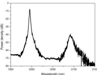
Cascaded Raman scattering is observed during injection of a 4.5 m long piece of MOF 3. When the pulse peak power is increased a peak appears around 2092nm for peak power around 0.8 W. Increasing peak power up to 4 W leads to generation of up to three peaks (Fig. 6). This is consistent with observation of cascaded Raman scatterings up to three orders due to the fiber normal dispersion at 1995nm. Figure 6 also illustrates the spectrum evolution for increasing peak powers. The second Stokes order appears at 2205 nm and third Stokes order appears at 2330 nm. The higher orders are broadened due to the Raman gain width. The second order and third order Stokes reach threshold for about 2 W and 4 W peak power respectively.
The fiber input cleave gets damaged for incident peak power reaching 130 W (corresponding to ~10 W injected peak power). Assuming that the incident beam size equals the mode effective area of the injection fiber i.e. 20 µm2, this corresponds to a damage threshold of ~650 MW/cm2.
Fig. 6. Spectrum of the light collected after MOF 3
Injection of 2 µm nanosecond pulses into the As-Se fibers in the normally dispersive regime leads to Raman scattering as modulation instability is prevented by dispersion and self-phase modulation is negligible for long pulses. The cascaded Raman scattering occurring in MOF 3 at very low power indicates that the suspended core structure considerably enhances the fiber non-linearity while enabling low losses leading to efficient Raman
#134005 - $15.00 USD Received 31 Aug 2010; revised 15 Sep 2010; accepted 18 Sep 2010; published 6 Dec 2010
conversion. Three Stokes orders have been observed for pulses with only 4W peak power. Presence of higher orders is currently under investigation however the mechanism will be quickly limited by fiber damages. We estimate the critical intensity for our fiber to be around 650 MW/cm2. This value is lower but in the same order of magnitude than 1 GW/cm2 usually stated [8].
As As-Se fibers with 3 µm suspended core are still normally dispersive, further core size reduction must be realized to lower the zero dispersion wavelength around 2 µm to generate a supercontinuum with the thulium laser source. This core size reduction should also improve the single mode behaviour of the planned As-Se MOF.
4. Conclusion
A new method using a silica mould has been investigated to manufacture chalcogenide microstructured optical fibers. This casting method allows the fabrication of chalcogenide MOF with losses close to the material ones. The combination of high purity synthesis with the moulding method permits to obtained losses smaller than 50 dB/km around 3.7 µm in a multimode fiber. Third order Raman scattering has been demonstrated at 2330 nm using a 1995 nm pump in a suspended core fiber. Even for the smallest core MOF, the pump is in the normal dispersion regime. The future studies will be devoted to smaller core MOFs, in tapered fibers for example, that can permit to pump near the zero dispersion wavelength. In the present study, the pulse duration was in the nanosecond regime that leads mainly to Raman effects. Investigations for shorter duration pulse are also carried out to reach larger spectral broadening in mid infrared.
Acknowledgement
The authors want to thank French ANR (Confian), DGA and Région Ile de France for their financial supports.
#134005 - $15.00 USD Received 31 Aug 2010; revised 15 Sep 2010; accepted 18 Sep 2010; published 6 Dec 2010

![Fig. 2. Optical attenuation curve: MOF 1 (dotted line) and MOF 2 (straight line). Inset: zoom of the [3, 4.4] µm window](https://thumb-eu.123doks.com/thumbv2/123doknet/11626485.305269/6.918.215.709.110.361/fig-optical-attenuation-curve-dotted-straight-inset-window.webp)