HAL Id: hal-00482682
https://hal.archives-ouvertes.fr/hal-00482682
Submitted on 27 May 2010
HAL is a multi-disciplinary open access
archive for the deposit and dissemination of
sci-entific research documents, whether they are
pub-lished or not. The documents may come from
teaching and research institutions in France or
abroad, or from public or private research centers.
L’archive ouverte pluridisciplinaire HAL, est
destinée au dépôt et à la diffusion de documents
scientifiques de niveau recherche, publiés ou non,
émanant des établissements d’enseignement et de
recherche français ou étrangers, des laboratoires
publics ou privés.
A memory Mapping Approach for Parallel Interleaver
design with multiples read and write accesses
Cyrille Chavet, Philippe Coussy
To cite this version:
Cyrille Chavet, Philippe Coussy. A memory Mapping Approach for Parallel Interleaver design with
multiples read and write accesses. IEEE International Symposium on Circuits and Systems (ISCAS),
May 2010, Paris, France. page 3168-3171, �10.1109/ISCAS.2010.5537955�. �hal-00482682�
A memory Mapping Approach for Parallel Interleaver design with multiples read and write accesses
C. Chavet, P. CoussyLabSTICC Lab., Université de Bretagne Sud Abstract-For high throughput applications, turbo-like iterative
decoders are implemented with parallel architectures. However, to be efficient parallel architectures require to avoid collision accesses i.e. concurrent read/write accesses should not target the same memory block. This consideration applies to the two main classes of turbo-like codes which are Low Density Parity Check (LDPC) and Turbo-Codes. In this paper we propose a methodology which always finds a collision-free mapping of the variables in the memory banks and which optimizes the resulting interleaving architecture. Finally, we show through a
pedagogical example the interest our approach. This research
was supported by the European project DAVINCI.
Index Terms - Parallel architecture, interleavers, turbo-like
codes, memory mapping.
1. INTRODUCTION
In the multimedia and telecommunications domain, continuously emerging customer services require severe performance to implement the new communication standards. Indeed, communication systems require high throughput -on the order of several hundred Mb/s- accompanied by both low latency and severe bit error rate BER constraints (e.g. wireless, fiber-optic communication…). Owing to their impressive near-Shannon-limit error correcting performance, turbo-like codes in their parallel or serially concatenated versions [3], originally dedicated to channel coding, or LDPC codes [5], are being currently reused in most of digital communication systems (e.g. equalization, demodulation, synchronization, MIMO…).
These coders are formed by two or more processing elements PE (encoders/decoders) and one communication network composed of steering components (multiplexers, butterflies, barrel shifters…) and memory elements (registers, RAMs…). This network interleaves the data blocks exchanged by the PEs according to a predefined rule named interleaving law or permutation law. The turbo-like decoding principle is based on an iterative algorithm using decoders exchanging information in order to improve the error correction performance through the iterations. The iterative nature of these algorithms is a severe constraint to satisfy the aforementioned requirements with an affordable implementation complexity. A widespread solution is to realize the decoder in a parallel fashion. On the one hand, this solution increases the throughput since the latency of the system becomes the latency of constituent sub-blocks [3]. On the other hand, the complexity and the cost of the system are increased due to parallel nature of the architecture.
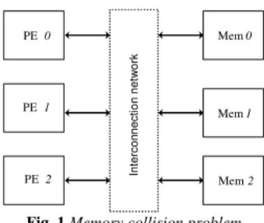
By the way, depending on the interleaving law, different parallel processing elements may try to simultaneously access the same memory block (cf. Fig. 1). This problem is known as the “collision” problem [11]. In this case, three classes of solution are available: The designer may
- define his own dedicated interleaving law in order to avoid such collision problems, but the resulting architecture may not be standard compliant.
- add extra memory elements and control logic in the communication network in order to buffer and postpone the conflicting data. - find a memory mapping avoiding any conflict access and taking into account the cost of the architecture (i.e. interconnection network). The paper is organized as follows: the second section presents the existing solutions to design parallel interleaver architectures.
Mem 0 Mem 1 Mem 2 PE 0 PE 1 PE 2 In te rc o n n e c ti o n n e tw o rk
Fig. 1 Memory collision problem
The third section is dedicated to the problem formulation of the interleaver design. In the fourth section we present the proposed approach to automatically find a memory mapping solution that avoids any conflict access. Finally, the last section presents experimental results on a pedagogical example.
2. RELATED WORKS
An interleaving law is a permutation law, also referred as π, that scrambles data to break up neighbourhood-relations [11]. It is a key factor for turbo-codes performances, which varies from one communication standard to another. Moreover for a given standard, different interleaving rules can be used for different modes through varying frame lengths and/or data rates [7]. In this context, taking into account the aforementioned constraints and the collision problems to design hardware implementations of parallel turbo decoders require the integration of complex interconnection network topology (cf. Fig. 1) supporting the intensive interleaved memory accesses. Indeed, in state-of-the-art parallel turbo-decoding, interleaving is considered as a limiting factor for the overall system performance and the architectural cost. To successfully tackle these problems, different solutions exist. Multiple solutions have been proposed in classical Single-Read / Single-Write approaches. A first solution to get rid of collisions with non prunable interleavers, consists in designing a specific interleaver rule. In [11], the authors propose a deterministic methodology to design collision-free interleavers. In [12] and [8] the authors define collision-free permutations thanks to a combination of a spatial and a temporal permutation. The authors of [14] simply integrate the collision-free constraint in the design of their interleaver. However, the multi-modes architectures (depending on the frame length, the data-rate…) cannot be handled by such approaches. Another solution consists in defining a collision-free interleaver that preserves this property even when pruned. In [7], the authors describe a design rule to obtain such interleavers, with an incremental algorithm that generates collision-free interleavers by adding new elements in successive steps, to a small initial permutation. Of course, all these solutions are viable if and only if the designer is free to choose the permutation law to be used in the system. As a consequence, the resulting architecture may not be standard compliant.
A second approach consists in adding extra memory elements in the communication network. The aim is to buffer and to postpone the conflicting data. In [19] the authors propose, when a collision appears, to store the conflicting information in the communication network until the targeted sub-block can process it. Of course, the additional network buffering resources, and consequently the time needed to interleave information, increase with the number of parallel processors. This is a suboptimal strategy, in terms of latency and thus throughput, which avoids collisions at the
expense of area and memory. Moreover, the communication is based on a Benes network [2], which might be suboptimal compared to a dedicated and optimized architecture. Unlike these implementations, in [15] the authors propose a solution based on software and/or reconfigurable parts to achieve the required flexibility, but achieving lower throughput. In [17], an advanced heterogeneous communication network implementation was proposed. Two multistage interconnection network architectures are presented in order to handle on-chip communications in multiprocessor parallel turbo decoders. They are based on a dedicated network and associated routers. The main feature of these network architectures (Butterfly and Benes based topologies) is their supposed scalability enabling seamless trade-off between hardware complexity and available bandwidth for turbo decoding. The Butterfly network, which lacks of diversity, is a multistage interconnection network with 2-input 2-output routers. There is a unique path between each source and destination. As a consequence, the conflicts risk is increased and the authors have to add queues to store conflicting information. The second network architecture proposed is based on a Benes network. In this case, the latency is constant for all the couples (source, destination), but this network avoids the conflicts if and only if all the paths have a different destination. Unfortunately, it has been shown that it was not true for turbo-decoding applications because interleaving (respectively de-interleaving) ends in potential conflicts. Moreover, as already mentioned the Benes networks are costly and under-optimized solutions. In [15] the authors propose another on-chip interconnection network adapted to a flexible multiprocessor LDPC decoder based on a De Bruijn network. This network allows to efficiently supporting the communication intensive nature of the application. The conflict access are avoided thanks to a dedicated routing algorithm.
A third solution consists in finding a memory mapping avoiding any conflict access. This problem can also be seen as a graph colouring problem [13]. In the graph the vertices represent the data to be stored and the edges show the conflict existing between data accessed in parallel. In our case, node colouring algorithms cannot be able to propose a minimal graph colouring as we demonstrate it in the next section. The edge algorithm [9] is based on a divide-and-conquer strategy, uses Euler partition to perform this colouring on bipartite multigraph. This king of approach is able to find the minimal edge colouring in polynomial time. Nevertheless, this theoretical approach does not take into account the resulting steering logic complexity.
Other methods have been proposed to find a solution to this problem. Hence, the authors of [18] describe an approach that avoids collisions for any interleaver and any degree of parallelism. Contrary to the literature belief, the author have proven that for any code and any read/write operations scheduling, there exist a suitable memory mapping that grants a collision-free access. This solution automatically finds a collision-free data memory mapping respecting the interleaving rule, thanks to a simulated-annealing algorithm. As a consequence, the user cannot predict when the algorithm will end. Moreover, the proposed approach neither targets the optimization of the storage elements, nor the optimization of the interconnection network.
Finally some solutions based on a set of elementary memorising elements (Registers, FIFO, LIFO), such as [4], have been proposed. But if these solutions are able to generate strongly optimized architectures, they cannot, to this day, target memory block based architecture.
In this paper, we present an approach which is able to deal with the memory mapping in block-based and parallel interleaver architectures with multiple accesses to the data. This solution
generates a conflict-free in-place memory mapping for any interleaving law (as well as [18] or [19]) and it is able to optimize the interconnection network (as well as [12]) in order to target a specific steering component to obtain an optimized interconnection network between the PEs and the memory banks (if the interleaving rule enables to use this steering component, e.g. a barrel-shifter, a butterfly…).
3. PROBLEM FORMULATION
Let us consider a set of L elements E={e0 ,…eL-1}. As an example,
LDPC codes require that each element will be processed N times by the processing elements. The parallelism P represents the number of processing elements required in order to achieve throughput constraints. The number of parallel memory banks B needed to store these data equals P, i.e. B={b0,…bP-1}. In order to equilibrate
these memory banks, each of them has to store M=L/P data.
4 5 2 4 6 3 1 3 6 1 5 2 2 4 5 6 3 1 4 5 2 4 6 3 1 3 6 1 5 2 2 4 5 6 3 1 Time Parallelism
Fig. 2 Data accesses matrix
As a pedagogical example, Fig. 2 represents the data accesses for such a decoding approach. In this example, three processing elements compute data and store the results in three memory banks, through an interconnection network (see Fig. 1). In this matrix, each row refers to the data processed by a given processing element and the column represents the time through the successive steps of the decoding algorithm to process this block of data. The multiple occurrences of a given data represent the iterative accesses to this data. These accesses can be interleaved in time, e.g. data 3 is successively accessed in the first and the second column, even if all data have not been yet accessed: the first access to data 4 is performed in third column.
Valid mapping constraint
In order to ensure the correctness of the proposed memory mapping, the constraint to be respected is: if two data ei and ejare
accessed at the same time, i.e. if there exists a column in the matrix in which data eiand ej appear, then their respective memory
mapping must be different.
Formal approach for memory mapping
In section 2, this memory mapping problem has been shown very similar to the graph colouring problem. Unfortunately, node colouring approaches are not suited to solve our problem. Fig. 3
represents the conflict graph extracted from the matrix (cf. Fig. 2). In such a graph, if two nodes (i.e. two data) are linked by an edge, this means that these data are accessed in parallel during a processing step (i.e. a column of the matrix).
1 2 3 4 6 5 1 2 3 4 6 5
Fig. 3 Conflict access graph
In this conflict graph, the biggest clique gathers 5 data (Data 2, 3,
4, 5 and 6). As a consequence, any off the shelf node colouring algorithm will result in a 5-colouring solution. This means that using this approach, the user has to implement 5 memory banks to store the data (instead of the 3 memory banks required in this case). Fortunately, this weakness can be overcome.
The solution consists in taking into account separately the reads and writes accesses of each data from/to the memory. This means that any data ei should be (1) read in a memory bank bj, (2)
processed by a PE and then (3) stored in another memory bank bk.
In this case, if two data eiand ejare accessed at the same time,
then they must be read in different memory banks and the results will be written in different memory banks. Of course, in order to optimize the resulting architecture, these memory switches have to be minimized and done if possible by using a regular permutation scheme (such as circular permutation that can be implemented for example with a barrel-shifter based network).
A dedicated design approach is thus needed. This approach has to respect both the interleaving rule and the design constraints (the parallelism, the number of memory bank, the size of the memory banks, the latency, the throughput…). In order to optimize the architecture, the approach has also to take into account the steering components required by the designer.
4. PROPOSED APPROACH
A. Memory Mapping Constraints and Objectives
The previous mapping constraints will guarantee that the generated mapping is valid. In addition, algorithmic constraints also require that the first read access of a data eihas to be done in same the
memory bank bk, used for the last write access to this same data.
The architectural objectives will be used to guide the memory mapping algorithm in order to implement an optimized interconnection network based on specific steering components (e.g. a barrel-shifter based network) if possible.
B. Algorithm
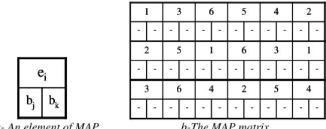
The algorithm we propose uses a matrix (MAP in Fig. 4.b) in order represents the memory mapping. In this matrix, two mapping cells, initially empty, are associated to each data ei. These cells
correspond to the memory banks in which the read and write memory accesses for this data are performed. The Fig. 4.a presents an element of the memory matrix. In this example, the data eiis
read in the memory bank bj and then stored in the memory bank bk.
bk bj
e
i bk bje
i -2 4 5 6 3 1 -2 4 5 6 3 1 -1 3 6 1 5 2 -1 3 6 1 5 2 -4 5 2 4 6 3 -4 5 2 4 6 3a- An element of MAP b-The MAP matrix
Fig. 4 Mapping matrix MAP for the matrix accesses presented in Fig. 1
If a given data appears several time in the mapping matrix, then the read memory access of the ith occurrence of the data must be performed in the same memory bank than the write memory access of the (i-1)th occurrence of this data. This memory mapping matrix will be filled according to the aforementioned constraints. Mapping constraint:
- In any column of MAP each memory has to be used only one time for the read accesses and only one time for the write accesses. - The first read access to a given data is performed in the same memory bank than its last write access.
Architectural objectives:
- The memory mapping in a given column of MAP for the read access (resp. write access) has to respect the rules of the steering components that compose the network.
- The number of different memory read access (resp. write access) for a given processing element, i.e. a line in matrix MAP, has to be minimized in order to reduce the control complexity.
The initialization of our mapping algorithm consists in assigning memory banks for the first column of the matrix MAP in Fig. 4.b. By default, the read and write access to a data are performed in the same memory bank. Next, since each of these data is accessed for the first time, their memory banks are reported in the last write access to this data.
Once this update has been done, the algorithm selects the next column in MAP and tries to find the read and write memory mapping for the data which have not been assigned, with respect to mapping constraints and architectural objectives. To do this, the algorithm constructs for all empty mapping cells of the selected column a list of all available memory banks (observing the mapping constraints for the current column). This mapping list is ordered by taking into account the targeted architecture (the first elements are those which implement the targeted communication network).
If a valid mapping is possible, i.e. all the lists generated for the current column have at least one element, then the mapping is done with the first element of each list.
Else if there is no mapping solution respecting the aforementioned constraints, then for the conflicting data, the algorithm selects a data D in the current column which has already been assigned to a couple of memory banks in the past (i.e. in one of the previous column in matrix MAP). The algorithm chooses the earliest occurrence of D in the past (i.e. column CNear). Then the write
memory access of D in CNear is exchanged in order to be mapped to
a memory bank which will solve the conflict access in the current column.
Of course, this change generates a local write access conflict to be solved. This resolution is performed by swapping the memory banks of the two conflicting data, if these write accesses can be modified (i.e. this is not the last write access to the data). This correction is then propagated in the rest of the matrix MAP if needed. If some of the data in the current column are accessed for the first time, then their mapping is reported in the last write access to these data and the recursion is performed.
The resulting matrix represents a conflict free memory mapping for the given interleaving law, and also gives the control steps of the interleaving network. Our recursive algorithm is thus able to find a valid memory mapping, and each time the interleaving law enables it, this mapping will by construction respect the input architectural objective.
5. PRATICAL IMPLEMENTATION
Let us take as an example a matrix (see Fig. 2) with 3 PEs. The first step of our mapping algorithm consists in assigning a memory bank for a first set of data, e.g. the first column of MAP inFig. 5: data 1 in this first column of MAP, the data is first read in the memory bank b0, and then the result is stored in the same memory
bank b0. -b0 b0 2 4 5 6 3 1 -b0 b0 2 4 5 6 3 1 -b1 b1 1 3 6 1 5 2 -b1 b1 1 3 6 1 5 2 -b2 b2 4 5 2 4 6 3 -b2 b2 4 5 2 4 6 3
Fig. 5 Initialization of the mapping matrix
Then, the last write accesses to these data in the matrix are assigned to the same memory bank as can be seen in bold in Fig. 6. Once this update has been done, the algorithm selects the next column and assigns a memory mapping with respect to both the mapping constraints and architectural objectives.
b1 -b0 b0 2 4 5 6 3 1 b1 -b0 b0 2 4 5 6 3 1 b0 -b2 -b1 b1 1 3 6 1 5 2 b0 -b2 -b1 b1 1 3 6 1 5 2 -b2 b2 4 5 2 4 6 3 -b2 b2 4 5 2 4 6 3
Fig. 6 Memory mapping of the last write access
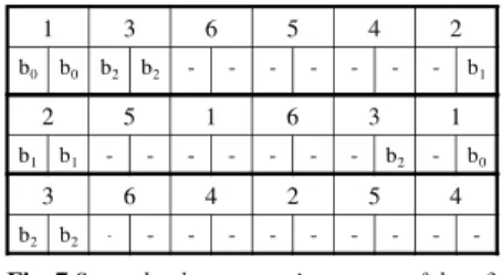
In Fig.7, the data 3 in the second column has been previously mapped to bank b2 (in the first column), then the read access to this
data should be done in b2. Then this bank is reused for the current
write access. 1 3 6 5 4 2 b0 b0 b2 b2 - - - b1 2 5 1 6 3 1 b1 b1 - - - b2 - b0 3 6 4 2 5 4 b2 b2 - - -
-Fig. 7Second column mapping report of data 3
The other data are accessed for the first time so the algorithm first constructs the mapping solutions lists for these data. Then the memory mappings of the current column are performed and the read accesses of data 5 and 6 are reported to their last write accesses in
MAP (see Fig. 8).
b1 -b2 b2 b0 b0 2 4 5 6 3 1 b1 -b2 b2 b0 b0 2 4 5 6 3 1 b0 -b2 -b1 -b0 b0 b1 b1 1 3 6 1 5 2 b0 -b2 -b1 -b0 b0 b1 b1 1 3 6 1 5 2 -b0 -b1 b1 b2 b2 4 5 2 4 6 3 -b0 -b1 b1 b2 b2 4 5 2 4 6 3
Fig. 8Second column mapping
Then, our algorithm is performed on the rest of the matrix until it reaches a conflict (Fig. 9). In this case, the data 6 has just been written (previous column) to bank b1, but data 2 is also stored in
the bank b1 (first column mapping).
b1 -b1 b1 b2 b2 b0 b0 2 4 5 6 3 1 b1 -b1 b1 b2 b2 b0 b0 2 4 5 6 3 1 b0 -b2 -b1 -b0 b0 b0 b0 b1 b1 1 3 6 1 5 2 b0 -b2 -b1 -b0 b0 b0 b0 b1 b1 1 3 6 1 5 2 b2 -b0 -b2 b2 b1 b1 b2 b2 4 5 2 4 6 3 b2 -b0 -b2 b2 b1 b1 b2 b2 4 5 2 4 6 3
Fig. 9 Mapping conflict in the fourth column
To solve this problem, the algorithm selects the conflicting data which has been mapped during the nearest column in the past, i.e. in our example: data 6. Then, its write access is exchanged with the write access of data 4, as can be seen inFig. 10.
b1 -b0 b0 b2 b1 b2 b2 b0 b0 2 4 5 6 3 1 b1 -b0 b0 b2 b1 b2 b2 b0 b0 2 4 5 6 3 1 b0 -b2 -b1 b2 b0 b0 b0 b0 b1 b1 1 3 6 1 5 2 b0 -b2 -b1 b2 b0 b0 b0 b0 b1 b1 1 3 6 1 5 2 b2 -b0 -b2 b1 b1 b2 b1 b1 b2 b2 4 5 2 4 6 3 b2 -b0 -b2 b1 b1 b2 b1 b1 b2 b2 4 5 2 4 6 3
Fig. 10 Solving the mapping conflict in the fourth column
Next, the algorithm is applied on the rest of the matrix, see Fig. 11. The mapping matrix gives the interleaving network control information: the sequential accesses to the memory banks are a
representation of the control state machine of the interconnection network. b1 b2 b1 b1 b0 b0 b2 b1 b2 b2 b0 b0 2 4 5 6 3 1 b1 b2 b1 b1 b0 b0 b2 b1 b2 b2 b0 b0 2 4 5 6 3 1 b0 b0 b2 b2 b1 b2 b0 b0 b0 b0 b1 b1 1 3 6 1 5 2 b0 b0 b2 b2 b1 b2 b0 b0 b0 b0 b1 b1 1 3 6 1 5 2 b2 b1 b0 b0 b2 b1 b1 b2 b1 b1 b2 b2 4 5 2 4 6 3 b2 b1 b0 b0 b2 b1 b1 b2 b1 b1 b2 b2 4 5 2 4 6 3
Fig. 11 The final memory mapping 5. CONCLUSION
In this paper, we have presented a memory mapping methodology to design parallel interleaver architecture with multiple read/write access. This methodology allows to generate a valid memory mapping in any case and avoids the limitation of the traditional graph colouring approach. If the interleaving law enables it, the resulting memory mapping will optimize the resulting interconnection network.
REFERENCES
[1] S.Benedetto, D.Divsalar, G.Montorsi and F.Pollara,“Serial concatenation of interleaved codes: Performance analysis, design, and iterative decoding”, IEEE
Trans.Inf.Theory, vol.44, no.3, pp.909–926, may 1998.
[2] V.E.Benes,“Mathematical Theory of connecting network and telephone trafic”, New York, N.Y.: Academic, 1965.
[3] C.Berrou, A.Glavieux, and P.Thitimajshima, “Near-Shannon limit errorcorrecting coding and decoding: Turbo codes,” in Proc. IEEE Int. Conf Commun., vol. 2, Geneva, Switzerland, 1993, pp. 1064–1070. [4] C.Chavet, P.Coussy, P.Urard, E.Martin,”A Methodology for Efficient Space-Time Adapter Design Space Exploration: A Case Study of an Ultra Wide Band Interleaver”, p. 2946-2949, ISCAS 2007.
[5] J.C.MacKay David and R.M.Neal, “Near Shannon limit performance of low density parity check codes”, Electronics letters, July 1996. [6] R.Diestel, “Graph Theory”, vol. 98 of Graduate Texts in Mathematics, Springer-Verlag, July 2005.
[7] L.Dinoi and S.Benedetto,“Variable-size interleaver design for parallel turbo decoder architecture”, IEEE Trans.On Comm., vol.53, no11, Nov.2005. [8] R.Dobkin,M.Peleg and R.Ginosar,“Parallel VLSI architectures and parallel interleaving design for low-latency MAP turbo decoders”,Tech.Rep.CCIT-TR436.
[9] P.Erdős and R.J.Wilson,"Note on the chromatic index of almost all graphs", Journal of Combinatorial Theory, Series B23: 255–257, 1977. [10] H.N.Gabow, “Using Euler Partitions to Edge Color Bipartite Multigraphs”, International Journal of Computer and information Sciences, vol. 5, no.4, p.345-355, December 1976.
[11] A.Giulietti, L.Van Der Perre and M.Strum, “Parallel turbo coding interleavers: avoiding collisions in accesses to storage elements”, Electronics Leters, vol. 38, no. 5, pp.232–234, Feb. 2002.
[12] D.Gnaedig, E.Boutillon, M.Jezequel, V.C.Gaudet, and P.G.Gulak, “On multiple slice turbo codes,” in Proc. 3rd Int. Symp. Turbo Codes, Related Topics, Brest, 2003, pp. 343–346.
[13] M. Kubale, “Graph Colorings”, American Mathematical Society, 2004, ISBN 0-8218-3458-4.
[14] J.Kwak and K.Lee, “Design of dividable interleaver for parallel decoding in turbo codes”, Electron. Lett., vol.38, no.22, pp.1362–1364, Oct. 2002. [15] A.La Rosa, C.Passeron, F.Gregoretti and L.Lavagno, “Implementation of a UMTS turbo-decoder on dynamically reconfigurable platform”, proceedings of DATE 2004, Paris.
[16] H.Moussa, A.Baghdadi, M.Jezequel, “Binary de Bruijn on-chip network for a flexible multiprocessor LDPC decoder”. 45th
ACM/IEEE DAC, p.429-434, 2008.
[17] O.Muller, A.Baghdadi, M.Jezequel, “ASIP-based multiprocessor SoC design for simple and double binary turbo decoding”, DATE 2006. [18] A.Tarable, S.Benedetto, and G.Montorsi, “Mapping interleaving laws to parallel turbo and LDPC decoder architectures”, IEEE Trans.Inf. Theory, vol. 50, no.9, pp.2002-2009, Sep. 2004.
[19] M.J.Thul,F.Gilbert, and N.Wehn, “Optimized concurrent interleaving architecture for high-throughput turbo-decoding,” in Proc. 9th Int. Conf. Electron., Circuits, Syst., vol.3, pp.1099–1102, 2002.