TH `ESE
TH `ESE
En vue de l’obtention du
DOCTORAT DE L’UNIVERSIT ´E DE TOULOUSE
D´elivr´e par :l’Universit´e Toulouse 3 Paul Sabatier (UT3 Paul Sabatier)Pr´esent´ee et soutenue le29/09/2017 par :
Florian WODLEI
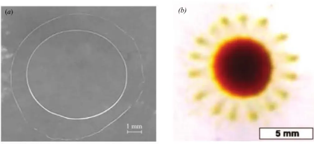
Self-Pulsations of a Dichloromethane Drop on a Surfactant Solution
JURY
FABIANBRAU Charg´e de Recherche
PIERRE-ANTOINEBONNEFONT Maitre de Conf´erences MARTINEMEIRELES Directeur de Recherche
THIERRYONDARC¸UHU Directeur de Recherche
ANTONIOSTOCCO Maitre de Conf´erences V ´ERONIQUEPIMIENTA Professeur d’Universit´e
´Ecole doctorale et sp´ecialit´e
SDM : Chimie macromol´eculaire et supramol´eculaire - CO044
Unit´e de Recherche
Laboratoire des Interactions Mol´eculaires et R´eactivit´e Chimique et Photochimique (UMR 5623)
Rapporteurs
Fabien BRAU et Pierre-Antoine BONNEFONT
Directeur de Th`ese
Es ist doch nicht genug, eine Sache zu beweisen, man muß die Menschen zu ihr auch noch verführen. [It is still not enough to prove something, one also has to seduce the people to it]
Friedrich Nietzsche
dedicated to Helfried Biernat Professor in theoretical Plasmaphysics (1947-2016)
Acknowledgement
Before everyone else I have to thank my supervisior Véronique PIMIENTA, who not only helped me in scientific respects during these three years but also taught me what it means to be "pragmatic" in doing research, which is something that will help me with my future research projects. I also appre-ciated a lot the collegial atmosphere we had in carrying out the research.
The theoretical part of my research was developed together with Charles ANTOINE, to whom I’m very thankful for his help and also the collegial atmosphere in which we were working together. I thank also Jacques MAGNAUDET and Julien SEBILLEAU from the institute of fluid mechanics (IMFT) with whom we were collaborating.
I also want to thank my teachers at high school, Jan Albert RISPENS, who was my chemistry and biology teacher and Mihnea HRISTEA, who was my physics and maths teacher who prepared my path in science, which was continued by Helfried BIERNAT and Hans-Hennig von GRÜNBERG at the university.
A very big thanks goes to Marcello BUDRONI and Federico ROSSI who made the connection to the scientific community in which I am working now which eventually led me to my supervisor and the research topic which is the subject of this work.
In regards to the PhD defence I thank all the members of my jury, especially my two reporters Fabian BRAU and Pierre-Antoine BONNEFONT for their detailed comments on my work.
I also thank all my friends who supported and helped me during these last three years, especially Giuseppe ALBERTI, Andreas GAVRIELIDES and Suhail USMANI.
At the end I also want to thank all the members of the laboratory, the new laboratory director Christophe MINGOTAUD as well as the old one, Monique MAUZAC for their support. In this context I want to mention also Charles-Louis SERPENTINI who helped me with the technical part of my work, as well as Sebastian CAZIN from the Institute of fluid mechanics (IMFT), who advised me with the high speed camera.
Last but not least I thank my family, my parents, grandparents and my brother for their support as well as my girlfriend Jessica FRANCO, who supported me especially in the last months.
Florian WODLEI November 2017
Contents
General Introduction 1
1 Surface-Tension induced Motion and Deformation on Solid and Liquid Surfaces 5
1.1 Introduction to Capillarity . . . 7
1.2 Spreading of Drops on Liquid Surfaces . . . 16
1.3 The Marangoni Effect and Related Instabilities . . . 18
1.4 Motion of Objects on Solid and Liquid Surfaces . . . 20
1.5 Pulsating Drops on Liquid Surfaces . . . 31
1.6 Conclusion . . . 32
Bibliography . . . 34
2 The Dichloromethane Drop on a Surfactant Solution: General Introduction 39 2.1 Historical Origin of the System . . . 41
2.2 A drop of DCM on a CTAB solution . . . 42
Bibliography . . . 48
3 The Evolution during the Induction Period 49 3.1 Appearance of an Induction Period . . . 51
3.2 Self-Pinning of the Drop . . . 56
3.3 Discussion . . . 64
3.4 Conclusion . . . 65
Bibliography . . . 67
4 The Pulsating Regime 69 4.1 Introduction . . . 71
4.2 Phenomenology of the Drop Pulsations . . . 72 III
IV Contents
4.3 Periodic Self-Pulsations . . . 73
4.4 Drop and Rim Expansion . . . 76
4.5 Rayleigh-Plateau Instability . . . 78
4.6 Expanding Toroidal Rim . . . 80
4.7 Interpretation . . . 92
4.8 Modeling . . . 94
4.9 Conclusion . . . 99
Bibliography . . . 101
5 Addition of Surfactant in the Organic Phase: The Flower-like Dewetting Pattern 103 5.1 Introduction . . . 105
5.2 Observations . . . 105
5.3 Interpretation . . . 111
5.4 Comparison of the two Pulsating Regimes (with and without CTAB in the Drop) . . . 114
5.5 Conclusion . . . 116
Bibliography . . . 117
General Conclusion 119
APPENDIX
A Materials and Methods I
A.1 Reagents . . . III
A.2 Physico-chemical Properties . . . III
A.3 Method of Placing the Drop . . . III
A.4 Optical Setup . . . III
B Stability of the Drop on the Surface V
B.1 Observations . . . VII
B.2 Modeling . . . IX
C Programs and Macros XV
C.1 Side View Extractor . . . XVII C.2 Spherical Cap Approximation - Mathematica Program . . . XXXIII
General Introduction
General Introduction
In the last 15 years there has been a growing interest in synthetic, chemical systems capable of un-dergoing autonomous shape changes and self-motion. This is also related to new kinds of possible applications in miniaturization techniques. In microfluidics for example such phenomena appear as a possible answer to problems related to fluid circulation and homogenization of microreactors. The induced motility of these systems is also a key motivation in the domain of artifical cell design. Motility is one of the vital functions of microorganisms in search of new resources. The aim here is to reproduce different propulsion modes observed in biological systems in order to identify the pos-sible energy source and observe the shape and trajectories spontaneously chosen to adapt to motility. Far-from-equilibrium chemical systems seem to be able to answer these demands. These systems exhibit a wide variety of spatial and temporal patterns known as dissipative structures. The inter-play between physico-chemical processes and mass or heat transfer may give rise to spatio-temporal structures induced by convective flows. The conversion from chemical to mechanical energy is at the origin of a wide variety of dissipative structures such as regular convective cells, interfacial deforma-tion, eruptions, interfacial turbulence or emulsification. These flows, triggered by density or surface tension gradients are crucial to many natural and man-made situations as for instance, extraction processes, spreading of spills in aquifers, oil recovery, ocean and atmospheric flows and of course chemical reactors at all scales.
When the phases in contact exhibit very different sizes, this energy conversion may set the smaller phase into spontaneous motion. This is the case with liquid drops on solid or liquid substrates . With drops, the scale of the object and those of the convective cells interfere, leading to strong deformation and sometimes directional motion. Drops are perfect models for laboratory experiments and theo-retical development.
In this work we will explore a drop of dichloromethane that undergoes remarkable shape transfor-mations when put on a aqueous solution of different concentrations of cetyl trimethylammonium bromide (CTAB). Among these shape transformations there is one with a striking periodicity: a pul-sating drop. The main focus of this work will be on this regime, which appears for a surfactant concentration below the critical micellar concentration (cmc).
The first chapter is a bibliographic approach to the subject describing several systems designed for motion or pulsations on liquid surfaces. It serves as well as an introduction to the theoretical concepts used throughout this work.
The system is introduced in chapter 2 from a historical point of view and by describing the successive regimes observed by varying the CTAB concentration. In chapter 3, we focus on the induction
pe-riod observed for specific experimental conditions that exists before the instability starts. The shape evolution showed an unexpected behavior for a drop deposited on a liquid surface. Based on par-ticle image velocimetry (PIV) measurements we propose an interpretation, which is confirmed by a simple analytical model. Chapter 4 and 5 are devoted to the pulsating regime. In chapter 4, we study the case where the surfactant is only in the aqueous phase. Starting from analyzing the periodicity of the pulsations, we focus on the rim that forms at the end of each pulsation and breaks-up into many small droplets, which are ejected radially. The manner in which this rim breaks up resembles to an instability known as the Rayleigh-Plateau instability. Nevertheless the rim break-up in this sys-tem here has its origin in more than one instability, involving also thermal convection induced by a Benard-Marangoni effect. An analytical model has been developed in order to check our hypothesis. The addition of surfactant to the organic phase, discussed in chapter 5, reveals a new flower pattern, that occurs during the dewetting stage of the pulsating drop. This dewetting also involves very ordered droplet ejection from the "flower petals". We propose a qualitative explanation of the global behavior of the drop and compare these results to the regime observed in the absence of surfactants. At the end of the main chapters (3,4 and 5) a summary of the chapter is given in French.
Introduction générale
Au cours des 15 dernières années, un intérêt croissant est apparu pour des systèmes chimiques syn-thétiques donnant lieu spontanément à des modifications de forme ou capables de motilité. Ces travaux sont en relation avec des applications dans les techniques de miniaturisation. En microflu-idique, par exemple, de tels phénomènes pourraient apporter des réponses à des problèmes liés à la circulation des fluides ou l’homogénéisation de microréacteurs. The motilité induite dans de tels systèmes est également à l’origine de leur intérêt dans le domaine du design de cellules artifi-cielles. Se déplacer est l’une des fonctions vitales des microorganismes à la recherche de nouvelles ressources. Le but est dans ce cas de reproduire différents modes de propulsion observés dans ls systèmes biologiques dans le but d’identifier les sources possibles d’énergie et d’observer la forme et les trajectoires choisies spontanément pour s’adapter au mouvement.
Les systèmes hors équilibre sont susceptibles de répondre à de telles motivations. Ces systèmes montrent une grande variété de structures spatiales ou temporelles connues sous le nom de struc-tures dissipatives. Le couplage entre processus physico-chimiques et le transfert de matière ou de chaleur peuvent donner lieu à la formation de structures spatio-temporelles induites par des flux convectifs. La conversion d’énergie chimique en énergie mécanique est à l’origine de grande var-iété de structures dissipatives telles que des cellules de convection, des déformations interfaciales, des éruptions, de la turbulence interfaciale ou des phénomènes d’émulsification. Ces flux, induits par des gradients de densité ou de tension superficielle sont cruciaux dans différentes situations naturelles ou industrielles comme par exemple pour les processus d’extraction, la récupération du pétrole, les flux océaniques ou atmosphériques et dans les réacteurs à toutes les échelles.
Quand ls phases en contacts sont de taille très différente, cette conversion d’énergie peut mettre la phase de plus petite taille en mouvement. Ceci est le cas pour des gouttes sur surfaces solides ou liquides. Pour les gouttes, la taille du système et des cellules de convection interfèrent menant à de fortes déformations ou à la motilité. Les gouttes apparaissent comme des modèles parfaits pour des expériences en laboratoire et le développement de théories. Dans ce travail, nous allons explorer le comportement d’une goutte de dichlorométhane qui donne lieu à des transformations remarquables de sa forme lorsqu’elle est déposée sur des solutions de bromure de cétyltriméthylammonium de concentration différente. Parmi ces transformations, il y en a une montrant une périodicité sur-prenante : la goutte pulse de façon régulière. Le sujet principal de cette thèse porte sur ce régime qui apparait pour une concentration en tensioactif inférieur à la concentration micellaire critique (cmc). Le premier chapitre est une approche bibliographique du sujet décrivant plusieurs systèmes capa-bles de se déplacer ou montrant des pulsations sur surfaces liquides. Il constitue également une introduction aux concepts théoriques utiles tout au long de ce travail.
Le système est ensuite introduit dans le chapitre 2 d’un point de vue historique et par la description des régimes successifs observés en faisant varier la concentration de CTAB. Au chapitre 3, nous nous intéressons plus particulièrement sur la période d’induction observée avant le début de l’instabilité. L’évolution de la forme de la goutte montre un comportement inattendu sur surface liquide. Des mesures de vélocimétrie par imagerie de particules (PIV) nous a permis de proposer une interpréta-tion du phénomène et de proposer un modèle analytique simple rendant compte de nos observainterpréta-tions. Les chapitres 4 et 5 sont dédiés au régime de pulsation. Au chapitre 4, nous avons étudié le cas où le tensioactif se trouve uniquement dans la phase aqueuse. Nous nous sommes en particulier intéressés au bourrelet qui se forme à l’extrémité du film en expansion et donne lieu après rupture à l’éjection de gouttelettes en direction radiale. L’instabilité est similaire à une instabilité de Rayleigh-Plateau mais elle présente ici des propriétés particulières liées à des phénomènes thermiques. Un modèle an-alytique a été développé dans le but de vérifier nos hypothèses. L’addition de tensioactifs à la phase organique, discuté au chapitre 5, révèle une nouvelle structure hautement ordonnée qui apparait lors de la phase de démouillage du régime de pulsation. Nous proposons une interprétation qualitative du comportement de la goutte et une comparaison des systèmes en présence et en l’absence de CTAB dans la goutte.
À la fin des chapitres principaux (3,4 et 5) un résumé du chapitre est donné en français.
1
Surface-Tension induced Motion and
Deformation on Solid and Liquid
Surfaces
Erst wenn du die Stadt verlassen hast, siehst du, wie hoch sich ihre Türme über die Häuser erheben. [Only after you leave the city you see how high its towers rise above the houses.] Friedrich Nietzsche
In this Chapter we will introduce the theoretical background needed to understand the basics of surface tension induced motion and deformation of drops on solid and liquid surfaces. This will be followed by a literature study on the existing systems, that move, spread and transform themselves on liquid (and solid) surfaces.
1.1. Introduction to Capillarity 7
1.1. Introduction to Capillarity
In this section we will introduce the theoretical concepts to understand surface-tension induced mo-tion and deformamo-tion of objects on liquid and solid surfaces. This secmo-tion is based on the books of de Gennes [1], Adamson [2] and on the articles by Brochard-Wyart [3], Sebilleau [4] and Bonn et al. [5] for the topic of "pseudo-partial" wetting.
Etymologically speaking, capillarity (also known as capillary action) is the phenomenon that pulls a
liquid in a narrow tube upwards against the gravity force1. The word capillarity is also used in a more
general way to cover interfacial phenomena between immiscible liquids or liquids and gases. The research field investigating these phenomena was founded by Pierre S. de Laplace [6] and Thomas Young [7] in the beginning of the 19th century and has grown nowadays to a huge field of scientific research with applications in the fields of physical chemistry (e.g. microdroplets in microfluidics [8]), biology (e.g. lipid droplet formation in the biological cell [9]) and industry (e.g. inkjet printing or coating of surfaces [10]).
1.1.1. Cohesive and Adhesive Forces
The forces that hold any body together are the so called cohesive2forces which are weaker in a liquid
than in a solid and therefore allow the liquid to be more flexible and adaptable than a solid. This is the reason why a liquid can flow but still doesn’t change significantly its volume.
When a liquid gets in contact with another liquid, gas or solid, there are new forces acting: the
adhesive3forces, which are the forces between the different substances that hold them together.
By looking at the microscopic picture of matter, these forces have their origin in the interactions between the molecules from which they are build up. A molecule inside the bulk is submitted to all the forces of the other molecules surrounding it in such a way that the net force equals zero in average (these forces are the cohesive forces). In contrast, at the interface with another liquid, solid or gas a molecule is submitted to forces from the molecules of its kind and also to the forces of the molecules or atoms of the other substance. If these forces are different from the one of its own kind the molecule will feel a non-zero net force.
If the other substance is in the gaseous state, the cohesive forces are much bigger than the adhesive ones and the molecules at the interface will feel a net force that is directed inside the bulk of the liquid. Therefore a molecule at the interface is immediately pulled back into the bulk. As a result other molecules from the bulk are now exposed to the interface which again will be pulled back into the bulk (see Fig. 1.1).
1the word capillary comes from the latin word capillus which stands for a a long narrow diameter tube 2from Latin cohaerere which stands for stick or stay together
8 Chapter 1. Surface-Tension induced Motion and Deformation on Solid and Liquid Surfaces 1 2 3 4 5 6 7 8 9 10 11 12 13 14 1 2 3 4 5 6 7 8 9 10 11 12 13 14 15
A
B
interface gas phase liquid phaseFigure 1.1: Simplified schematic microscopic pictures of the molecular interactions at a gas/liquid interface. Cohesive forces between the molecules are shown in black, adhesive forces in red dashed; the molecules of the liquid phase are num-bered to show their change in position after an instant due the fact that they experience a non-zero net force (big red arrows). B shows the situation of A at a later instant.
1.1.2. Surface Tension as an Energy
This dynamic process at a microscopic level, that results in the exposure of the smallest possible amount of molecules to the interface, leads at a macroscopic picture to the fact that the surface area of the interface will tend to be minimal for a given volume.
For example the equilibrium state of a liquid drop in a gas phase is therefore the state of a perfect sphere (neglecting gravity), since this is the state with the minimal surface area for a given volume of liquid. Any other state with a surface different from a sphere is a non-equilibrium state and is accompanied by a higher free energy. The increase in the free energy is directly proportional to the increase in the surface area while the proportionality factor is the surface tension denoted :
dGsurf ace= · dA. (1.1)
Its value is directly linked to the cohesive energy per molecule, U, which is the energy that holds a molecule inside the bulk. The energy needed to increase the surface area by an amount of dA is therefore equal to the energy for maintaining the number of molecules N at the interface. This area
dAis N · a, where a is the surface area of one molecule and the energy is N times the energy needed
to keep one molecule at the surface.
1.1. Introduction to Capillarity 9
one molecule at the surface is aroundU
2. So the energy needed to increase the area by an amount of
dAis therefore N·U2 . Rewriting and comparing it with Eqn. (1.1) leads to
dGsurf ace=N· U
2 =
U
2· adA, (1.2)
where the surface tension is given by
= U
2· a. (1.3)
For water which has a quite strong cohesive energy around 18 kT (⇡ 7 · 10 20J at 25o C) due to
hydrogen bonds, this leads to a surface tension of around 72 mN/m. For most oils it is around kT
(⇡ 4 · 10 21Jat 25oC) which leads to surface tensions around 30 mN/m.
1.1.3. Spreading and Wetting
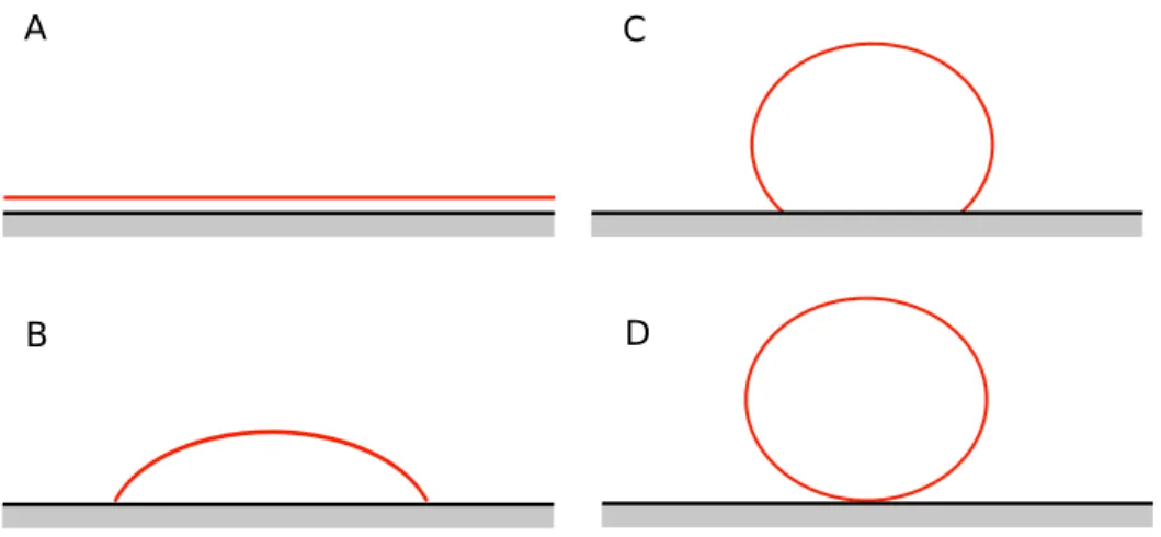
When a liquid is spreading on a solid or liquid surface, it is said that the liquid is wetting the sur-face. Depending on the cohesive forces and the adhesive forces between the liquid and the solid two scenarios are possible: (i) the total wetting case, where the drop spreads to cover the surface (Fig. 1.2 (A)) and (ii) the partial wetting case, where the drop reaches an equilibrium shape with a given con-tact angle (see Fig. 1.2 (B)). The non-wetting case can be seen as a special case of the partial wetting
case with a contact angle bigger than 90o(see Fig. 1.2 (C,D)).
A
B
C
D
Figure 1.2: Spreading of liquids on solid surfaces. A: Total wetting. B: Partial wetting. C: Non-wetting. D: Perfect
non-wetting.
The equilibrium state of a liquid drop on a solid surface in the partial wetting case is given by the Young equation, which will be derived here from a thermodynamical point of view. Fig. 1.3 shows
10 Chapter 1. Surface-Tension induced Motion and Deformation on Solid and Liquid Surfaces an equilibrium state of a drop on a solid surface showing the contact angle ✓ and the connected sur-face areas.
The system has three surfaces and a contact line, where these three interfaces meet called the triple contact line.
A
glA
lsθ
A
gsA
glA
/sA
gsθ
triple contact line
A
B
Figure 1.3:A liquid drop on a solid surface. A: side view showing the contact angle, ✓. B: A 3-dimensional view showing the corresponding surface areas and the triple contact line.
By calculating the change in the free energy of the system, the equilibrium state of the droplet is obtained. An infinitesimal change in the free energy is accompanied by an infinitesimal small change in the spreading of the drop (see Fig. 1.4). This change of energy is given by
dG = @G @Ags dAgs+ @G @Agl dAgl+ @G @Als dAls= gsdAgs+ gldAgl+ lsdAls, (1.4)
where the subscripts of the surface areas, gs, gl and ls are denoting the interfaces gas/solid,
gas/liq-uid and liqgas/liq-uid/solid respectively. In terms of the increase in the surface area dAls, the change of the
energy is given by
dG = gs+ glcos ✓0+ ls dAls, (1.5)
where dAgs= dAlsand dAgl= dAlscos ✓0allows to express the other areas in terms of the area dAls
(see inset of Fig. 1.4). At equilibrium the change in energy is zero, which is equivalent to the bracket being zero in Eqn. (1.4), or in other words:
1.1. Introduction to Capillarity 11
A
g/lA
l/sA
g/sθ
A
g/lA
l/sA
g/sA
B
θ
θ'
dA
l/sθ'
θ
θ'
dA
l/sdA
g/lFigure 1.4: Spreading of liquid drop on a solid surface. A: side view showing the change in surfaces and contact angle (inset showing the relation between the surfaces at the triple contact lines). B: Corresponding 3-dimensional side view of the spreading.
This equation is known as the Young equation.
1.1.3.1. Contact Angle Hysteresis
If the drop is volatile and losing volume due to evaporation or if volume is sucked away by a syringe,
the contact line will not move but stay pinned and the contact angle will decrease4. This contact angle
which will be smaller than the equilibrium contact angle is called receding contact angle, ✓R. On the
other hand if the volume of the drop is increased with a syringe, the contact line again will not move but the contact angle will increase. This contact angle, bigger than the equilibrium contact angle, is
called the advancing contact angle, ✓A. Pinned evaporating drops have been extensively studied in the
framework of the so-called "Coffee ring" effect [12].
4This depends on the hydrophobic and hydrophilic interactions between the drop and the surface. A water droplet for
example can be pinned on a hydrophilic surface while it will not pin on a hydrophobic one, where it will shrink due to evaporation by maintaining the equilibrium contact angle [11].
12 Chapter 1. Surface-Tension induced Motion and Deformation on Solid and Liquid Surfaces
1.1.3.2. The Spreading Parameter
The initial wetting state can be predicted by the spreading parameter S, which is defined as the difference between the free energy per surface area of the dry surface and the free energy per surface area of the wetted surface, i.e.
S = gs ( gl+ ls) (1.7)
where gs, gland lsare the surface tensions at the gas/solid, gas/liquid and liquid/solid interfaces,
respectively.
If the parameter S is positive, i.e. gs > ( gl+ ls), a liquid spreads and wets the surface completely
(total wetting case), while in the case of S negative, i.e. gs< ( gl+ ls), a drop spreads until it reaches
the equilibrium contact angle calculated above (partial wetting case).
The spreading parameter is commonly used to predict the spreading behavior of a drop on a solid and liquid surface. Due to the possible evolution of the surface tensions the spreading parameter can become also time dependent.
In general it is not possible to determine the equilibrium spreading coefficient S from the pure inter-facial tensions since as in the example illustrated above the surfaces can be modified by the forma-tion of films or/and the modificaforma-tion of its composiforma-tion due to evaporaforma-tion and/or the adsorpforma-tion of surfactants. A benzene droplet placed on a water surface for example spreads out shortly after its deposition and then retracts to form a droplet [5]. This means that the initial spreading parameter
Si > 0, while the equilibrium spreading parameter S < 0. Since the interfacial tension between water
and benzene is low, complete wetting is initially favored. This effect becomes overpowered by the modification of the water/air interface by the formation of a microscopic benzene film that lowers the corresponding interfacial tension.
In general, in such systems the spreading behavior can be understood by the evolution of the spread-ing parameter S(t), rather than by its equilibrium value.
1.1.4. Surface Tension as a Force
The surface tension can also be interpreted as a force that acts tangentially to the surface and per-pendicular to the contact line and in the direction that minimizes the surface (see Fig. 1.5). The free energy can be written as:
dG = dA = ` dx = ` ~· d~x, (1.8)
where ` is the circumference of the surface A, d~x is a vector in the direction of the increase of A and
1.1. Introduction to Capillarity 13
is the interfacial tension, where ~e|| is the tangent unit vector to the surface perpendicular to the
circumference.
A
B
dx
γ
A/Be
||Figure 1.5:Interpretation of the surface tension as a force acting at the contact line ` between phases A and B. This point of view is commonly used to derive the Young equation by writing down the equilibrium
of forces at a point of the triple contact line5(see Fig. 1.6).
Agl Als Ags θ
γ
lsγ
glγ
gsFigure 1.6:Interfacial forces acting on the triple contact line for a liquid droplet on a solid surface.
Everything derived so far is also applicable to a liquid drop on a liquid interface. The only difference is that the supporting interface is not rigid anymore and is deforming itself according to the forces acting on it (see Fig. 1.7).
Agl All' Agl' θ
γ
glγ
ll'γ
g/' θ1 θ2 θ3Figure 1.7:Interfacial forces acting on the triple contact line for a liquid droplet on a liquid surface.
5due to the fact that the solid substrate does not deform, only the horizontal projections of the force ~g/lenters the equation
14 Chapter 1. Surface-Tension induced Motion and Deformation on Solid and Liquid Surfaces A relation between the parameters can be obtained again by writing down the equilibrium of forces at a point at the triple contact line i.e.
gl’cos ✓3= glcos ✓1+ ll’cos ✓2 ll’sin ✓2= glsin ✓1+ gl’sin ✓3
(1.10)
where gl, ll’and gl’are the surface tensions at the gas/liquid, liquid/liquid and gas/liquid(bulk)
interfaces, respectively. On the other hand at equilibrium the forces also have to fulfill the vector equation
~ls+ ~gl+ ~ll’= ~0 (1.11)
which can be graphically represented by a triangle, the so called Neumann triangle (see Fig. 1.8). In this way the following equation for the contact angle ✓ can be obtained by using the law of cosines:
cos ✓ = 2 gl’ gl2 ll’2 2 gl ll’ . (1.12)
θ
γ
g/lγ
l/l'γ
g/l' θ1 θ2 θ3θ
180
o-θ
γ
g/l'γ
g/lγ
l/l' A BFigure 1.8:A: Neumann construction of the forces at the triple contact line. B: Neumann triangle.
1.1.5. Pseudo-Partial Wetting and Thin Films
The case where a liquid lens, that is formed at a water gas interface, is in equilibrium with a sur-rounding thin film is called pseudo-partial wetting (see Fig. 1.9).
To find the equilibrium state of such a system the free energy density of the film is investigated, which reads
g(h) = gl+ ll’+ ˜(h). (1.13)
Here ˜(h) is the contribution of long range forces across the film of thickness h. In the limit h ! 0, i.e.
when the film reduces to the gas/liquid(bulk) interface, ˜(h) = Si to retrieve the gas/liquid(bulk)
1.1. Introduction to Capillarity 15 Agl
All'
Agl'
h
Figure 1.9:Pseudo-partial wetting. A drop in equilibrium with a surrounding thin film of thickness h. molecular forces vanishes. To find an expression for ˜(h) the change in free energy of the system that is generated by the presence of the liquid film is calculated. The free energy of the system reads
G(h) = ( gl+ ll’+ P (h))A, (1.14)
where P (h) is the free energy per area that arises from the interaction of the underlying liquid with the gas phase through the thin film of liquid of thickness h. A is the surface area of the film. By keeping the volume of the film constant, the change in free energy that is accompanied by the increase of the film area A is obtained:
dG = gldA + ll’dA + d(P (h)· A) = ✓ gl+ ll’+ P (h) hdP (h) dh ◆ dA. (1.15)
Comparing with Eqn. (1.13) we get the expression for ˜(h), i.e.
˜(h) = P (h) hdP (h)
dh . (1.16)
The spreading dynamics in the pseudo-partial wetting regime is therefore determined by P (h). Re-garding the limit h ! 0 of ˜(h) the expression of P (h) for this case can be already determined:
lim h!0˜(h) = limh!0 ✓ P (h) hdP (h) dh ◆ = lim h!0P (h) | {z } :=P (0) ! = Si ) P (0) = Si (1.17)
From theoretical considerations6:
P (h) = AH
12⇡h2 for do< h <1 (1.18)
is obtained, where dois the molecular distance and AHis the effective Hamaker constant, which is a
measure for the strengths of the London-van der Waals interaction energy7.
6assuming London–van der Waals interactions between the liquid and the gas phase through the liquid film of thickness
h [13]
7the effective Hamaker constant is a sum of all contributions, i.e. A
H= Al0g Agg+All0 Allwith Aijthe corresponding
Hamaker constants for the interface ij. The van der Waals interaction of the gas phase for non-volatile is neglectable, leading to AH⇡ All0 All
16 Chapter 1. Surface-Tension induced Motion and Deformation on Solid and Liquid Surfaces Knowing this, the four simplest cases of the possible dependency of P on the thickness h will be discussed here (see Fig. 1.10). For a positive Hamaker constant (orange curves) the case of total wetting is obtained. Partial wetting and pseudo-partial wetting are obtained for a negative Hamaker constant. The pseudo-partial wetting is obtained when the curve of P (h) shows a minimum. This
minimum corresponds to the equilibrium film thickness hmin of the film that is surrounding the
drop. In general the situation is not as simple as shown in Fig. 1.10 since the dependency of P (h) can be quite complex for small h.
A
H
>0
A
H
<0
P(h)
h
1/h2 -1/h2S
i>0
hminS
i<0
Figure 1.10:Dependency of the P (h) on the film thickness that determines the wetting behavior (the four simplest cases); dashed lines are the curves ±1/h2, that serve as asymptotes. Orange curves (AH> 0): Total (Si> 0) and partial (Si< 0) wetting. Red curves AH< 0: Partial (Si< 0) and pseudo-partial (Si> 0) wetting.
In general, the possibility of a lens having a thin film of thickness h surrounding it, is determined by the initial spreading parameter and the value of the effective Hamaker constant.
1.2. Spreading of Drops on Liquid Surfaces
Spreading of one liquid on the surface of another is studied since the early 70s in regard to oil slicks and the spreading of crude oil on sea water [14, 15, 16, 17, 18].
A volume of a less denser liquid spreads out on a denser one due to gravity and surface-tension forces, which are counterbalanced by viscous forces. The rate of spreading is following a power law, i.e.
1.2. Spreading of Drops on Liquid Surfaces 17
r(t) = k· tn, (1.19)
where r(t) is the radius of the oil slick at the time t and k is a factor depending on the volume, the spreading parameter, the density, the gravitational acceleration and the viscosity of the bulk. The exponent n can range from 1/10 to close to 1 depending on the systems and the processes involved. Classically three regimes are observed for these kind of systems, which are governed by the rela-tive importance of different forces. As spreading initiates, it starts with a regime where inertia and gravity are important. k is only depending on the relative densities and the volume and n is 0.25. As the volume of oil gets thinner viscous forces get more important and k now also depends of the viscosity of the bulk phase and the power exponent n increases to 0.5. In the last regime, gravity effects decrease and only surface tension and viscous forces determine the spreading. In this case k only depends on the spreading parameter and the viscosity of the bulk phase. In summary:
r(t) = ( ⇢V )1/4 t1/4 gravitiy-inertia regime r(t) = ✓ ⇢V2 ⌫1/2 ◆1/6 t1/2 gravitiy-viscous regime r(t) = ✓S2 ⇢2⌫ ◆1/6
t3/4 Surface tension-viscous regime
Here ⇢ is the difference between the densities of the liquids, ⇢ is the density of the bulk phase, V is the volume, ⌫ is the viscosity of the bulk phase and S is the spreading parameter. The spreading of a volume of oil on a water surface is therefore passing subsequently from a gravity-inertia regime over a gravity viscous regime to finally reach a surface tension-viscous regime when it is already very flat. Spreading in the surface tension-viscous regime is called Marangoni-driven spreading.
The spreading of flat oil lenses is therefore expected to follow a Marangoni-driven spreading and a power law with n =0.75, but there are also other parameters that can influence the spreading dy-namics as the height of the bulk fluid layer, the presence or creation of surfactants, the fact that the two liquids are partially miscible or the evaporation of the liquid lens.
Dussaud and Troian [19] found for spreading with evaporation on a deep fluid layer a reduced spreading exponent of n = 0.5. They attribute this to a visible convective roll right beneath the lead-ing edge of the expandlead-ing drop, which was caused by evaporation and subsequent surface coollead-ing of the rapidly spreading film according to a Benard-Marangoni instability.
Santiago-Rosanne et al. [20] showed that the spreading follows also a power law in the case of par-tially miscible liquids. The value of the spreading parameter S, the power and the pre-factor k are
18 Chapter 1. Surface-Tension induced Motion and Deformation on Solid and Liquid Surfaces largely influenced by dissolution and the thereby induced convections and the height of the fluid layer. They found a spreading exponent around n = 0.5 for fluid layers thicker than 3.5 mm and a reduction of the spreading exponent down to n ⇠ 0.1 for smaller fluid layer heights.
Van Nierop et al. [21] investigated the spreading behavior of a reactive oil drop. They observed that the initial spreading was followed by the retraction of the drop with a spreading exponent between 0.64 and 0.89.
Generally speaking, spreading of liquid lenses on liquid surfaces follow a power law with exponents ranging between 0.1 and 0.9 depending on the particularity of the system. The more complex the systems the more difficult it is to theoretically predict their spreading dynamics.
1.3. The Marangoni Effect and Related Instabilities
The movement, that is induced on the surface due to surface tension inhomogeneities is known as the Marangoni effect (see Fig. 1.11) and the induced flows are sometimes referred to as Marangoni
flows [22].
γ
1 movement at the surfaceγ
2convection
γ
1 movement of the surfaceγ
2convection convection
γ
1 movement at the surfaceγ
2A
B
liquidliquid liquid
gas
Figure 1.11:The Marangoni effect. Movements at the interface that are induced by a difference in surface tension ( 2 > 1), which induce convective motions in the bulk phase. A: Gas/liquid interface. B: Liquid/liquid interface; convections induced in both phases, while their amplitude depends on the respective viscosities.
1.3. The Marangoni Effect and Related Instabilities 19 These flows can also induce motion in the bulk phase by transfer of momentum and depending on the viscosities of the two phases the induced convective motion can be different in the two phases. There are two main reasons for the creation of surface tension inhomogeneities at the surface. One is due to the temperature dependency of the surface tension and the other one is due to the dependency of the surface tension on the chemical composition of the interface.
A change in the surface tension can be induced by temperature changes of the surface or by the pres-ence of other substances on the surface. A Marangoni effect that is induced by temperature gradients is referred to as thermo-capillary Marangoni effect, while a Marangoni effect that is induced by the non-homogeneous chemical composition of the surface is referred to as soluto-capillary Marangoni
effect.
1.3.1. Tears of Wine and Rayleigh-Plateau Instability
The tears of wine is a well known phenomenon which is the continuous formation of liquid droplets, that fall along the wall of a wine glass.The phenomenon is known since ancient times and is
men-tioned even in the bible8. J. Thomson [23] identified the driving force for the upward flow necessary
for the formation of the liquid droplets as a gradient in surface tension. Later it was described by Marangoni [22].
The phenomenon is a consequence of the evaporation of alcohol, which has a lower surface tension and a lower boiling point than water which leads to Marangoni flows and a Rayleigh-Plateau-like instability [24] that leads to the formation of the droplets, which are sliding down the wall.
In the following we shall look in detail at the related mechanism.
At the wall of a glass filled with wine, adhesive forces induce the liquid to climb slightly on the glass wall of the glass to form a meniscus. Alcohol and water evaporate from the surface (Fig. 1.12, (A)), but due to its lower boiling point alcohol evaporates faster, changing the water/ethanol composition at the surface. This and also the decrease in surface temperature due to evaporation [25] result in an increase of the surface tension which induces Marangoni flows and more liquid is drawn up the wall from the bulk of the wine (Fig. 1.12, (B)).
At a certain point the accumulated liquid forms a rim (Fig. 1.12, (C)) which gets unstable and un-dulates and under the influence of gravity droplets are formed which are sliding down the wall of the glass (see Fig. 1.12 (D) and (E)). The formation of the droplets is assumed to follow a Rayleigh-Plateau like instability, which will be discussed in detail in chapter 4.
20 Chapter 1. Surface-Tension induced Motion and Deformation on Solid and Liquid Surfaces
A
B
C
D
γ1 γ2 evaporation γ1 γ2 γ1 γ2g
E
Figure 1.12:The tears of wine. A/B: Marangoni-induced flow which leads to a rise along the glass wall. C: At a certain point at the top a rim is formed, which gets unstable. D: From the rim droplets are created which are gliding down the glass wall. E: Three-dimensional illustration of the formation of the "tears" of wine from the formed rim.
1.4. Motion of Objects on Solid and Liquid Surfaces
There are many systems in the literature in which a drop or a solid moves on a solid or a liquid sur-face. The motivation of doing research on these systems are diverse: From mimicking the behavior of biological systems to systems which are manufactured in order to achieve a special task as transport, surface cleaning or energy transduction.
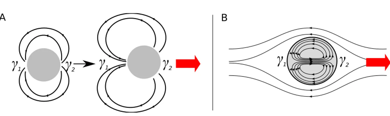
In general two main types of motions can be differentiated:
• Motion that is driven by the asymmetry of the interfacial tension surrounding an object on a solid surface or a liquid surface, where there is none or only little Marangoni-induced convec-tion, which we call in the following capillary-driven motion and
• motion that is mainly driven by Marangoni-induced convections, which we call in the follow-ing convection-driven motion.
There are many different ways to create a surface tension gradient on solid or liquid subphases. We will discuss here motion of drops on pre-prepared solid surfaces, that move due to the induced
1.4. Motion of Objects on Solid and Liquid Surfaces 21 surface tension gradient or that move autonomously by modifying the surface itself. On liquid sub-phases, we will discuss the motion of solids, gels and drops.
1.4.1. Capillary-Driven Motion
The motion of solid or liquid objects like solid scraps, specially manufactured boats or drops on surfaces can be achieved by surface tension differences between the back and the front of the object.
Due to this difference a driving force proportional to the difference in surface tension, i.e. Fdrive ⇠
2 1, will lead to the motion of the object in the direction of higher surface tension9.
Since the surface tension is depending on temperature and chemical composition of the substrate this difference in surface tension can be achieved by creating gradients of temperature or chemical composition on solid or liquid surfaces (schematically illustrated in Fig. 1.13).
1.4.1.1. Motion on a Solid Subphase
The motion of drops on solids under a horizontal temperature gradient is known for a long time [26]. One of the first who theoretically investigated this phenomenon was Brochard, who also considered the motion induced by pre-treated surfaces to obtain a chemical gradient [27]. Brzoska et al. [28] ex-perimentally investigated the motion induced by a temperature gradient on hydrophobic surfaces. Chaudhury and Whitesides [29] were able to make microliter drops of water run uphill an inclined
plane of 15o. To obtain this behavior a gradient of hydrophobicity was created by diffusing a vapor
of decyltrichlorosilane on a silicon wafer.
There is also the possibility that the motion itself modifies the surface and creates a self-induced au-tonomous motion of the drop.
9Assuming a surface tension variation along the triple contact line a driving force in direction of the higher surface tension
is obtained . The total force is given by
~ F =
Z2⇡ 0
~ (✓)d✓, (1.20)
where we will assume a symmetric distribution of surface tension between the two sides of the circular object and therefore ~ (✓)shall be
~ (✓) = 1+ ( 2 1) cos ✓ ~er, (1.21)
with~er= (cos ✓, sin ✓)(see Fig. 1.13 (A)).
Calculating the forces in x- and y-direction, leads to Fx = Z 2⇡ 0 [ 1+ ( 2 1) cos ✓) cos ✓d✓ = ⇡( 2 1) (1.22) Fy = Z 2⇡ 0 [ 1+ ( 2 1) cos ✓) sin ✓d✓ = 0 (1.23)
22 Chapter 1. Surface-Tension induced Motion and Deformation on Solid and Liquid Surfaces
γ
1γ
1γ
2γ
1γ
2 B Cγ
1γ
2γ
1γ
2γ
2 θ x y γ(θ) γ2 γ1 A DFigure 1.13: Schemes of capillary-induced motion of objects on solid and liquid surfaces ( 2 > 1). A: Surface tension gradient along the triple contact line. B: Motion of a drop on a solid surface presenting a surface tension gradient. C: Motion of a drop on a liquid surface induced by a low surface tension film that is formed around by its dissolution. Motion is spontaneously obtained if symmetry is broken. D: Motion of an object on a liquid surface that is induced by the deposition of a low surface tension substance on the surface.
A
B
Figure 1.14: Drops on solid surfaces. A: Schematic cross section of a decahydronaphthalene drop on a pre-prepared solid surface (Figure taken from [30]). B: Schematic cross section of an organic drop which moves by dissolving STA+ ions adsorbed to the glass surface (Figure taken from [31]).
An autonomously moving droplet was created by Domingues Dos Santos and Ondarçuhu [32] by putting a hydrophobic agent (1H,1H,2H,2H-perfluorodecyltriethoxysilane) inside n-alcane droplets
1.4. Motion of Objects on Solid and Liquid Surfaces 23 that left a dense grafted monolayer on a glass surface as it moved. The motion was initiated by gen-tly pushing the drop. The movement continued autonomously due to the creation of a hydrophobic monolayer at the backside of the drop that led to the surface tension difference. The drop was mov-ing autonomously as long as there was glass surface available. Lee and Laibinis [30] are followmov-ing a
similar idea. They prepared a surface of low surface tension (-CHO3) in which they engraved a track
of high surface tension (-CO2H) in which a solvent drop (decahydronaphthalene (DHN)) containing
alkylamine was deposited. The drop started spontaneously to move by creating a layer of alkylamine behind it, which has a lower surface tension and which led to the surface tension difference necessary to its motion (see scheme (A) in Fig. 1.14).
Another moving drop was investigated by Sumino et al. [31]. There, a glass slide was put in an aqueous phase of stearyl trimethyl ammonium chloride (STAC) on which STA+ ions got adsorbed. An organic drop containing an iodine solution of nitrobenzene saturated with potassium iodide was placed on the glass surface. The STA+ ions adsorbed to the glass surface were reacting in the oil drop to form STA-I, with the iodide ions created from the iodine present in the drop. This hydrophobic compound was dissolving in the oil drop, which left a clean surface with a lower surface tension behind it that maintained the difference in surface tension between the head and the tail necessary for its motion (see scheme (B) in Fig. 1.14).
Motion of drops on solid surfaces can also be induced by external stimulus. Ichimura et al. [33] in-vestigated a drop of olive oil that was moving on a solid surface covered by a photoisomerizable monolayer due to irradiation. Irradiating the surface with UV light started the isomerization pro-cess and made the surface hydrophilic while irradiating the surface with blue light had the opposite effect. The light-guided movement of the drop was realized by a spatially controlled irradiation to generate a gradient in the level of photoisomerization on the surface, which created the surface ten-sion gradient necessary for the motion of the drop. By moving the light-beam the drop could be moved along the surface.
A similar approach with a low-volatile drop (like diiodomethane) on a photo-modifiable surface was investigated by Berna et al. [34]. A glass or mica surface was covered with gold on which rotaxane molecules were physisorbed, which turned the surface hydrophobic. Irradiation with UV light changed the configuration of the rotaxane molecules and turned the surface more hydrophobic. Asymmetric irradiation of the drop on the surface led to its motion in direction of the irradiation.
The drop could also run uphill an inclined surface of 12oin this way.
1.4.1.2. Motion on a Liquid Subphase
On liquid surfaces one of the most studied autonomously moving object is the famous "camphor disk" (or camphor scrapping). The first explanation of its movements dates back to 1890 and was
24 Chapter 1. Surface-Tension induced Motion and Deformation on Solid and Liquid Surfaces given by Van de Mensbrugghe [35]. Lord Rayleigh [36] studied the effect of grease on the water sur-face on the self motion of the camphor scrapping.
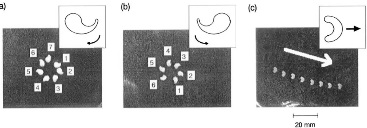
Figure 1.15:Camphor systems on liquid surfaces. A: Motion of camphor scrappings with different geometries that lead
to different kind of motions (Figure taken from [37]).
The group of Nakata is investigating this system since the 90s exploring many different aspects of its motion [37, 38, 39, 40, 41, 42, 43, 44].
The motion of camphor arises from the film of dissolved camphor that decreases the surface ten-sion around the disk. If the symmetry is broken, motion is induced towards the "clean" surface (like schematically illustrated in Fig. 1.13 (C)). Motion is maintained by the sublimation of the camphor, that restores the surface. By choosing special shapes of the camphor scrapping the random motion can be transformed into directional-controlled motion like rotation or translation. U-like shaped scraps lead to translational motion, while comma-like scraps lead to rotation (see Fig. 1.15). This is due to the fact that in concave regions of the scrap dissolving camphor will accumulate more than in convex regions. The concentration of camphor will be higher in concave regions lowering the surface tension more there than in convex regions. The corresponding difference in surface tension is again at the origin of motion.
Recently, the competition between convection and capillary induced motion was also investigated [38]. The system consisted of two geometries: a camphor disk and a camphor boat, i.e. a plastic plate on which on one side a piece of camphor was attached. The convections induced by the Marangoni flows had an inhibiting effect on the motion for the camphor boat (see Fig. 1.15 (B) (b), left col-umn) while an inverse picture was found for the camphor disk where the convections induced by the Marangoni flows were amplifying the effect of capillarity and therefore the motion (see Fig. 1.15 (B) (b), right column). In both cases the depths of the container increased the magnitude of the
con-1.4. Motion of Objects on Solid and Liquid Surfaces 25 vection and therefore the importance of the convection induced part of the motion.
Another similar system is the movement of aspirin crystals studied by Bansagi et al. [45]. Aspirin crystals of around 1 mm are placed on the water surface and start to move in regular circular and circular ellipsoidal motion. As the crystals slowly dissolve and hydrolyze the surface tension is low-ered locally. Additionally due to the difference in hydrophilicity of the facets of the crystal the surface surrounding the crystals is deformed asymmetrically. These two effects collaborate to the observed motion.
In the same category falls the autonomous motion of solid objects which release substances that decrease the surface-tension. Nakata et al. [42] has investigated the motion of a sodium oleate (soap) disk at an oil-water interface which was maintained by the release of oleate molecules. The motion of a capsule motor (polysulfone(PSf)-N,N’-dimethylformamide(DMF)) at the surface of an oil film on water was investigated by Zhao and Pumera [46], where the motion was induced due to the release of DMF from the very small pores of the solidified Psf capsule. Recently, Liu et al. [47] investigated a spindle-like "micro-motor" of around 10 µm of polycaprolactone containing an anionic surfactant (sodium 1-dodecanesulfonate) that was released to the water surface to obtain motion .
A
B
C
D
pH responsive part ethanol compartement
Figure 1.16:Milli- to centimeter-sized boats that move on liquid surfaces by expelling different solvents. A: Image of the SU-8 boat. B: Scheme of a SU-8 microboat showing the fuel compartment (Figure taken from [48]) and a modified SU-8 microboat to allow rotational motion (Figure taken from [49]). C: Boat that mimics the locomotion of the beetle of genus stenus (Figure taken from [50]).
26 Chapter 1. Surface-Tension induced Motion and Deformation on Solid and Liquid Surfaces There exists also the category of millimeter- to centimeter-sized manufactured boats that move au-tonomously on liquid surfaces and can also act as transport vehicles. Here the difference in surface tension surrounding the boat is obtained by the expulsion of a solvent having a lower surface tension than the surrounding liquid (see scheme (B) in Fig. 1.16) .
Qiao et al. [49] investigated the motion of an SU-8 microboat10 that uses isopropyl alcohol (IPA) for
propulsion (see Fig. 1.16 (A) to (C)).
Jin et al. [51] also use a centimeter-sized boat but the "fuel" is now provided by the vapor of volatile liquids like ethanol that is released to the surface where it reduces the surface tension.
Xiao et al. [50] investigated a similar system where they used ethanol as propellant. The originality of the system lays in the fact that their boat is mimicking the locomotion of the beetle of genus stenus. This beetle moves on the surface of water by emitting pygidial gland secretions that reduce surface tension in response to exteral stimuli [52]. To mimic the response to external stimuli they added a pH responsive part that controlled the release of ethanol. This part was a specially prepared surface that changed from superhydrophobicity to superhydrophilicity depending on the pH (see Fig. 1.16 (D)). Solids or amorphous solids are not the only one to move autonomously on liquid surfaces, there are also the category of gels that release a propellant that can move autonomously: A gel that released an organic solvent (alcohol or tetrahydrofuran) was investigated by Mitsumata et al. [53], [54], a PNIPAm gel soaked in ethanol on water was investigated by Bassik et al. [55] or the movement of a gel-based particle (ethanol-infused polyacrylamide hydrogel incorporated in a plastic tubing with one end closed) was investigated by Sharma et al. [56].
The last and most important category for us concerns drops that move and deform autonomously on liquid surfaces.
Nagai et al. [57] investigated the spontaneous motion of an alcohol droplet (pentanol) where the mo-tion is attributed to the asymmetry that arises due to the deformamo-tion of the droplet. The dissolumo-tion of the pentanol lowers the surface tension around the droplet and give rise to a surface tension gradi-ent. When the droplet volume was small (0.017 µL) the droplet was moving in an irregular manner, while for bigger drops (10 µL) a directed translational motion was observed. On such a drop a shape deformation is induced, which leads to a U-shaped drop (Fig. 1.17 (B)), similar to the shape of the U-shaped camphor scrap of Nakata [37] . The induced broken symmetry leads to the motion of the drop, like in the case of the camphor scrap. For large enough droplets the forces exerting on the droplet can also lead to its fission into many smaller droplets. The motion of the drop is attributed to an instability of the triple contact line that arises due to a solutal Marangoni effect. The dissolution and evaporation rate of the pentanol are important parameters for the transition from irregular to regular translational motion.
1.4. Motion of Objects on Solid and Liquid Surfaces 27
A B
Figure 1.17:Drops on liquid surfaces. A: Autonomous motion of an aniline drop. a) Schematic side view with details on the mechanism of motion. B: pentanol droplet moving autonomously on an aqueous solution; left: directed translational motion for a drop of 10 µL, right: top view of the U-shaped pentanol drop (Figure taken from [57]).
Another very interesting system is an aniline drop on an aqueous aniline solution which was in-vestigated by Chen et al. [58]. The drop shows two kinds of motion: beeline motion and circular motion. The first one is obtained for a drop deposited at the center of the subphase. However, this linear motion finally switches to circular motion to avoid repeated collision with the wall. In that regime motion has been maintained for hours. Evaporation and solubilization are relatively slow and the drop appears as a macroscopic drop coexisting with a surrounding precursor film. Motility was again ascribed to a surface tension imbalance at the front and rear of the drop. This difference, revealed by a difference in contact angle, was attributed to the precursor film and more precisely to the effect of fluid flow of the solution passing the drop. Driven by a Marangoni flow, the film may lose its initial symmetry. The initiated translation is then sustained by the distortion of the surface active film pointing to the rear of the drop. For small enough concentrations of aniline in the aqueous solution irregular motion is observed that can be attributed to the instability of the contact line, like it is the case in the pentanol drop discussed above.
1.4.2. Convection-Driven Motion
As described above the Marangoni effect can also induce convective flows in the bulk phase. For a drop this can induce convective motion inside the drop and in the surroundings of the drop. De-pending on the viscosities and the importance of the convective motion this can lead to the motion of the object itself. In contrast to the capillary-driven motion where the objects are moving always in direction of higher surface tension here the induced convections can lead also to a motion in the direction of lower surface tension (see schemes in Fig. 1.18).
28 Chapter 1. Surface-Tension induced Motion and Deformation on Solid and Liquid Surfaces
γ
1γ
2γ
1γ
2A
B
γ
1γ
2Figure 1.18:Convection induced motion ( 1> 2). A: Convection induced motion around a solid object. B: Convections induced inside and surrounding a drop that induces its motion.
Takabatak et al. [59] investigated a composite solid/liquid system, where an oleic acid drop was at-tached to a solid sodium oleate piece and placed on a water phase (see scheme in Fig. 1.19 (A)). The solid piece acted as a surfactant-supply that decreased locally the surface tension surrounding it, which induced Marangoni flows at the interface. As a result convective flows were induced around and inside the drop, which led to the motion of the drop. Self-motion in this system was obtained for minutes while motion also occurred in the non-composite system ( i.e. the drop of oleic acid alone) for some seconds. Observed motions are translational motion and circular motion. The type of motion was controlled by the size of the solid column, while translational motion was obtained for bigger sizes of the soap piece. These observations were also confirmed theoretically by Nagai et al. [60] where they showed that the two different types of motion occur due to a competition between convection flows and diffusion of the surfactant.
1.4.2.1. Motion Induced by an External Energy Source
Motion can also be induced by irradiation with light, as it is the case for drops on solid surfaces. An otherwise not moving drop can be brought into motion by irradiation with laser light which was investigated by Ichikawa et al. [61]. The irradiation with a a green laser light source (532 nm), that acts here as a local heat source can induce attractive and repulsive motion of a droplet of fluid paraffin on a sodium dodecyl sulfate (SDS) solution (see Fig. 1.19 (B)). The scrolling flows inside the droplet were induced by the direct irradiation and lead to a photophilic motion (i.e. a motion towards the irradiation zone) on a SDS solution while the same irradiation lead to a photophobic motion (i.e. a motion away from the irradiation zone) on pure water. This is is the result of the competition of the flows induced around the drop and inside the drop. Heating a spot on the surface of the drop induces a temperature gradient in the surrounding liquid and induced convective flows inside and outside the drop. Since the surface tension dependency on the temperature of an SDS solution is decreasing with increasing concentration of SDS the flows induced in the surrounding are getting
1.4. Motion of Objects on Solid and Liquid Surfaces 29 less and less important with the increase of the concentration of SDS, which explains why only the internal convective motions determine its motion.
A B C
Figure 1.19: Drops on liquid sufaces. A: Self-Motion of a liquid/solid composite system. Scheme of the induced flows
that lead to its motion (Figure taken from [59]). B/C: Laser induced motion of a drop of fluid paraffin on a sodium dodecyl sulfate (SDS) solution (Figure taken from [61]). B: Scheme of the setup. C: Top and side view of the colored paraffin drop on water and SDS. B: Flow field inside and outside the drop visualized with tracer particles. a) Droplet on pure water. b) Droplet on SDS solution.
Motion of droplets can also be induced by irradiating photoactive sub-millimeter sized droplets in an oleic acid solution with UV light [62]. The movement is now induced by a photoreaction which creates surfactants at the irradiated side of the drop and therefore lowers the surface tension there. This then induces Marangoni flows at the surface of the droplet which leads to its movement to-wards the light source. This kind of photo-manipulation was also used in Diguet et al. to move millimeter-sized oil droplets containing AzoTAB, a photoactive surfactant [63]. Irradiated with UV light, the photoactive surfactant transforms into its cis form (cis-AzoTAB) which has lower surface activity than the trans form. Irradiating one side of the drop with UV light leads to a motion away form the irradiation source while irradiating with visible light leads to the contrary. In both systems described here induced internal convective flows lead to the movement of the droplets.
1.4.2.2. Motion induced by an External Chemical Source
Drops can also move on liquid surfaces if they are placed on a non-homogeneous liquid bulk phase. Creating a pH gradient or any gradient of chemical species in a solution can induce such a non-homogeneous liquid bulk phase. This method is used for example to move polymer hydrogels (Wang et al. [64]) or drops (Lagzi et al. [65]) across mazes. As in the other systems discussed above motion is created by convective flows which are induced due to interfacial tension gradients.
30 Chapter 1. Surface-Tension induced Motion and Deformation on Solid and Liquid Surfaces
A
B
C
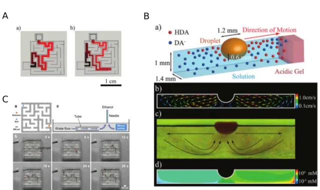
Figure 1.20: A: Maze solving by chemotactic droplets (two different outcomes of the same experiment; Figure taken
from [65]). B: Scheme and sideview showing the convective flows of the maze solving chemotactic droplet (Figure taken from [65]). C: Polymer hydrogel solving a microfluidic maze (Figure taken from [64]).
In the first example by Wang et al. [64], motion is induced by Marangoni driven spreading, where the source is far away from the spherical alginate hydrogel which is submerged in the water layer. When ethanol is dropped on water at some distance from the gel, ethanol spreads on the surface in an outward radial direction, the vacancy created at the injection point induces an upward flow and both result in the formation of a toroidal convective cell. The submerged hydrogel is dragged along by the flow on its way back in direction of the source. Moving the position of the injection point is an easy way to control the trajectory of the gel. The gel can also find the path to walk through a microfluidic maze when a fixed source is placed at the exit. Maze solving was also achieved, this time for floating drops, by Lagzi et al. [65]. A drop of a non-water soluble oil containing a weak acid was placed away from a fixed source of a strong acid (HCl). The weak acid which is surface active spreads around the drop where it gets partially deprotonated to a less surface active form. However, on the side of the HCl source, deprotonation is limited, giving rise to a steeper surface tension gradient. Convective rolls have been observed on each side of the drop but the spatial surface tension asymmetry results in a higher velocity of the roll facing the HCl source and so to the displacement of the drop in the same direction.
1.5. Pulsating Drops on Liquid Surfaces 31
1.5. Pulsating Drops on Liquid Surfaces
Pulsating drops are very rare in the literature. One of the few examples known is the oscillating min-eral oil drop containing a non-ionic, non-water soluble surfactant placed on water by Stocker and Bush [66]. The pulsations last for minutes but are not very regular (see Fig. 1.21). They are generated by the decrease of the oil/water surface tension due to adsorption of surfactants and an increase of the air/water surface tension due to evaporation of surfactants. This leads to a positive spreading parameter that induces an expansion of the drop (Fig. 1.21 II(a)). Subsequent partial emulsification at the lens edge due to surfactant accumulation lead to an decrease of the air/water interfacial ten-sion which causes the lens to retract (Fig. 1.21 II(b)). This behavior was sustained by the continuous evaporation and adsorption of the surfactants which led to the periodic change in the radius of the drop (see Fig. 1.22(a)).
I) II)
Figure 1.21:A pulsating drop mineral oil containing a non-ionic, non-water soluble surfactant (taken from [66]). I: (a) Pulsations of a 25 µm drop. (b) Pulsations of a 100 µL drop. II: Supposed mechanisms. a: Adsorption at the oil/water interface. b: Partial emulsification at the lens edge due to surfactant accumulation and surfactant evapororation.
The pulsations were modeled by Karapetsas et al. [67], where the theoretical results suggest a spread-ing exponent close to one. Another example of a pulsatspread-ing drop was investigated by Bates et al. [68]. A pulsating regime of a very short life time that gave rise to the ejection of a ring of droplets for a 1-butanol drop cooled to 1 C deposited on a 40 C water phase was observed (Fig. 1.22 (b)).
The last system to our knowledge that performs periodic pulsations is an immiscible, surface-active liquid droplet on thin liquid films of higher surface tension investigated by Sinz et al. [69]. Periodic pulsations of a surfactant drop are observed on a 780 µm thick glycerol film. Nevertheless the ampli-tude of these pulsations are very small (in the range of 20 um, i.e. 3% of the radius of the droplet). There is also a system with only one pulsation that was investigated by van Nierop et al. [21]. A heavy mineral oil drop of 0.1 µL containing oleic acid was placed on a sodium hydroxide solution.
32 Chapter 1. Surface-Tension induced Motion and Deformation on Solid and Liquid Surfaces (b)
Figure 1.22: Pulsating drops. a: A pulsating drop mineral oil containing a non-ionic, non-water soluble surfactant
(taken from [66]). b: A 1-butanol drop cooled to 1 C deposited on a 40 C water phase (taken from [68]).
In this system expansion with rim formation and subsequent retraction was observed. The expan-sion is due to the decrease of the oil/water interfacial tenexpan-sion as a result of a saponification reaction (sodium oleate is produced), while the recoil of the drop is due to the fact that diffusion overcomes the rate of surfactant production.
These systems show one or more aspects we also observe in the pulsating regime in the system under investigation in this work, which will be discussed in chapter 4 and 5 in detail.
1.6. Conclusion
In this chapter we have focused on the basics of capillarity including the Young and Neumann equa-tions for the equilibria of liquid drops on solid and liquid surfaces, the concept of the spreading parameter and the pseudo-partial wetting case, where a drop is in equilibrium with a thin film sur-rounding it.
The Marangoni effect, which is at the origin of motion of liquid or solid objects on liquid surfaces, was another topic deepened in this chapter. As illustrative example we discussed the phenomenon of "tears of wine", which is the result of the Marangoni effect combined with a Rayleigh-Plateau in-stability.
The second part of the chapter was devoted to the different systems that move on solid and liquid surfaces with the focus on drops on liquid surfaces. We distinguished two types of motion, the cap-illary driven motion, that arises due to surface tension differences at the two sides of the object and the convection driven motion.
bi-1.6. Conclusion 33 ological systems to systems, which are manufactured in order to achieve a special task as transport, surface cleaning or energy transduction.