HAL Id: hal-01229104
https://hal-ensta-paris.archives-ouvertes.fr//hal-01229104
Submitted on 16 Nov 2015
HAL is a multi-disciplinary open access
archive for the deposit and dissemination of
sci-entific research documents, whether they are
pub-lished or not. The documents may come from
teaching and research institutions in France or
abroad, or from public or private research centers.
L’archive ouverte pluridisciplinaire HAL, est
destinée au dépôt et à la diffusion de documents
scientifiques de niveau recherche, publiés ou non,
émanant des établissements d’enseignement et de
recherche français ou étrangers, des laboratoires
publics ou privés.
with E-HCF
Anne Wei, Gouzhi Wei, Benoit Geller
To cite this version:
Anne Wei, Gouzhi Wei, Benoit Geller.
Improving Mobile IPv6 Handover in Wireless
Net-work with E-HCF. IEEE Vehicular Technology Conference, Sep 2008, Calgary, Canada. pp.5-9,
�10.1109/VETECF.2008.294�. �hal-01229104�
T
Improving Mobile IPv6 Handover in Wireless
Network with E-HCF
Anne Wei
∗†, GouZhi Wei
∗and Benoit Geller
‡§∗
Universite´ Paris XII, 61 avenue du Ge´ne´ral de Gaulle, 94030 Cre´teil, France
†
Conservatoire National des Arts et Me´tiers, 292, rue Saint-Martin, 75003,Paris,France
‡SATIE – ENS Cachan, 61 avenue du Pre´sident Wilson, 94235 Cachan Cedex,France
§
LEI – ENSTA, 32 boulevard Victor, 75015 Paris Cedex,France
Email: [email protected]
Abstract— Mobile IP allows a mobile node to maintain a
continuous connectivity to the Internet when moving from one access point to another. However, due to the link switching delay and to the Mobile IP handover operations, packets designated to mobile nodes can be delayed or lost during the handover period. This paper presents a new control function called Extended Handover Control Function (E-HCF) in order to improve the handover performance in the context of Mobile IPv6 over wireless networks. With an analytical model and some OPNET simulations, we show in this paper that our solution allows to provide low latency, low packet loss to the standard handover of Mobile IPv6.
Index Terms— Mobile IPv6, Performance and Handover oper-
ations
I. INTRODUCTION
HE need to keep an ”everywhere and at any time” con- nection with Internet has been more and more demanded in recent years with the success of IEEE 802.11 and of IEEE 802.16 wireless networks standards. A growing number of 802.16/802.11 based wireless networks has been deployed in campuses, hotels, airports and companies as access networks to the Internet. The mobility support has thus become one very hot research subject. However, the continuous Internet connectivity and the correct routing of packets were not guaranteed when users change their access points to Internet with classical protocols. To resolve these problems, the Mobile IPv4 (MIPv4) and Mobile IPv6 (MIPv6)protocols [1], [2] were respectively published by the Internet Engineering Task Force (IETF).
Based on MIPv6, the main standards by the IETF are the Hierarchical Mobile IPv6 (HMIPv6) and the Fast Handover for MIPv6 (FHMIPv6). HMIPv6 introduces a Mobility Anchor Point (MAP) who acts somehow like a local Home Agent
(HA) for the visiting Mobile Node (MN). The concept of MAP can limit the amount of signaling required outside
the MAP’s domain [5], [7]. FHMIPv6 [8] can reduce the packet loss by providing fast IP connectivity as soon as a new link at the Link Layer is established. The network uses a Link Layer trigger to launch either Pre-Registration or Post-Registration handover operations. Besides of these main proposals, there has been some approaches for providing the
This work was supported in part by the international project PRA-SIP under Grant SIP04-03.
lossless handover and minimizing the handover delay [9]– [12], [14]. In [9], a Pre-Handover Signaling (PHS) protocol is
proposed in order to support the triggering of a predictive handover and to allow the network to achieve accurate han- dover decisions by considering different constraints such as Quality-of-Service (QoS), user profile and mobile node service requirements. In [10], a Hierarchical Network-layer Mobility Management (HNMM) framework is described in which an integrated IP-layer handover solution provides an optimized network connectivity. Also, a Competition based Soft Han- dover Management (CSHM) protocol [11] and a Multi-path Transmission Algorithm (MTA) [12] have been presented to decrease packet loss during a handover. Furthermore, the IEEE 802.11f standard including the Inter-Access Point Protocol (IAPP) enables the Access Points (APs) to communicate with each other, so that the Mobile IPv6 handover is improved at the Link Layer [14].
The goal of this paper is to optimize the Mobile IPv6 handover procedure by using a new function named Extended Handover Control Function (E-HCF). Based on our paper [3], the principle of the Handover Control Function (HCF) is that, according to the mobile node’s scanning result and the HCF router database, the HCF router can both pre-decide a mobile node’s new access point and a new IP address. So the mobile node can send Binding Update message when it is still connected with its previous access point. Contrarily to a standard MIPv6 handover for which the Detection Address Duplication (DAD) deteriorates dramatically the handover la- tency (see below), the HCF approach avoids any IP address collision without the use of DAD. In this context, we propose the E-HCF which not only inherits of the advantages of the
HCF, but also allows communications between some extra- HCF routers. Moreover, the E-HCF can buffer the packets
during the handover process in order to reduce the packet loss. The remainder of the paper is thus organized as follows: Section II presents our Extended Handover Control Function (E-HCF) architecture and the associated operations. Section III deals with the performance of the E-HCF handover in terms of handover latency and packet loss. Regarding the standard handover of MIPv6, O ur numerical a nd s i mul a t i o n r e s ul t s show that the E-HCF handover reduces significantly both the latency and the packet loss. Finally, some conclusion and future works are mentioned in Section IV.
II. EXTENDED HANDOVER CONTROL FUNCTION FOR MOBILE IPV6
A. E-HCF overview
Generally speaking, a handover consists of a Link Layer handover and of a Network Layer handover. The Link Layer handover includes a Discovery phase (scanning the channels to discover an available Access Point), an Authentication phase, and a Re-association phase, whereas the Network Layer handover is concerned by a Router Discovery phase, a De- tection Address Duplication (DAD) phase, a Binding Update phase and a Binding Acknowledgement phase respectively. As displayed on Figure 1, the standard MIPv6 handover latency has been estimated to a maximum value of 1290 ms [7]. This long latency is not acceptable for real time applications such as video and audio. If we analyze each phase during the Network Layer handover (Router Discovery, DAD, Binding Update and Binding Acknowledgement), we can note that the DAD latency costs almost 1000 ms and has a heavy weight on the global handover latency. As a result, in order to reduce the total handover latency, we now develop a procedure to avoid any
DAD operation during handover procedure.
Fig. 1. Standard MIPv6 Latency
We introduce a local intelligent entity called Extended Handover Control Function (E-HCF) which should be capable of controlling its attached Access Routers (ARs), Access Points (APs) and Mobile Nodes (MNs). As shown on Figure 2, linked directly with its ARs, each E-HCF router reserves beforehand a list of all available IP local addresses. The E-HCF router also generates and updates periodically a second list which records the used ARs/APs/IP addresses. By comparing these two lists, the E-HCF router can find a potential duplicate IP address (collision) in its domain. Then, this E-HCF router can withdraw this potential duplicate IP address or can ask a concerned sub-node to change its IP address. In this way, the E-HCF router enables to insure an unique IP address to a
MN without DAD.
Furthermore, an E-HCF router could exchange both some local information with its ARs/APs/MNs and some external information with other E-HCF routers. To realize our E-
HCF proposal, we propose six new messages: MN Request
(MNReq), MN Reply (MNRep), HCF Request (HCFReq), HCF Reply (HCFRep), Connection Established Information (CEInf) and Handover Finished Confirmation (HFCon) messages (for the detailed information about the formats of these messages see [15]).
For the mobile IPv6 protocol and IEEE 802.11/802.16 networks context, a MN surveys periodically the received signal strength. When the signal strength drops below a pre- defined threshold, the MN must discover and connect itself to a new available AP for granting its communication with its
Fig. 2. Architecture of Extended Handover Control Function (Router is an Access Router; E-HCF is an E-HCF router)
correspondence. It reports to its E-HCF router (via its attached
AR/AP) some AP’s Basic Service Set IDentifier (BSSID) and
signal strengths that it were probed. Based upon the reported information, the AR/AP’s loading and the MN’s Quality of Service (QoS) requirements, the E-HCF router decides which
AP, the MN shall associate with and notifies the MN about
the new AR/AP information, such as a new AP’s BSSID, an
AR interface address, a sub-network prefix and an IP address.
Consequently, the MN can configure its new Care-of-Address (CoA) and can take care of the Binding Update process even if it is still attached with its previous AR/AP. An E-HCF router can guarantee that the new IP address is unique thanks to the knowledge of its lists. If a MN moves to another domain, the E-HCF original router guarantees the new IP address by exchanging some data with the new E-HCF router. Moreover, in order to minimize the packet loss during a handover, an E-
HCF router stores packets into a buffer until the MN is really
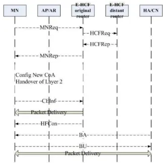
attached to the new IP address. The entire handover procedure is displayed on Figure 3.
Fig. 3. E-HCF Procedure (E-HCF original router is an attached router with an E-HCF function; the E-HCF distant/remove router is a router with who an E-HCF original router can communicate)
B. E-HCF Procedure
We first recall that HCFReq/HCFRep messages are used between E-HCF routers for extra-domain handovers. Each E-
HCF router must record and update its database periodically.
This database helps to decide an unique new IP configuration in order to adapt for MN movements without the DAD phase during a handover.
As illustrated on Figure 3, the E-HCF procedure is com- posed of the following steps:
• Moving in the network, if the threshold of the received signal strength is overstepped, the MN begins to probe the neighbor AR/AP’s information, including the signal strength, some IP addresses, AP’s BSSIDs, AR interface addresses and the sub-network prefix. Then the MN sends a MNReq message to its E-HCF original router (via its
AR/AP) to report this information.
• Receiving the MNReq message, the AR stops to forward all the packets sent to the MN and forwards them to its
E-HCF original router in order to avoid the packet loss
during the handover procedure.
• Receiving the MNReq message, the E-HCF original router decides to which AR/AP the MN will be associated. The choice of the AR/AP is mostly based on database obtained with periodic exchange messages from an E-
HCF router to another (HCFReq and HCFRep messages)
or with periodic exchange messages from ARs/APs/MNs. For example, if the number of registered MNs in one
AR or AP has reached a limit, the E-HCF original router
will not attach the MN to this saturated AR or AP. After making the previous decision, the E-HCF original router sends to the MN a MNRep message which consists of a new AP’s BSSID, an AR interface address, a sub-network prefix and a new IP address.
• With the MNRep message, the MN can obtain its new
CoA and configure it automatically.
• The MN sends a CEInf message to its E-HCF original router to confirm its new attachment.
• After receiving the CEInf message, the E-HCF original router transfers the buffered packets to the MN’s new
CoA. Then, the E-HCF original router sends an HFCon
message to end the handover procedure.
• The MN can then exchange Binding Update (BU) and Binding Acknowledgement (BA) messages with its home agent and its correspondent node.
As shown in the E-HCF procedure, a MN can obtain its new
CoA before it really attaches to its next AR/AP. Moreover, any DAD latency (about 1000 ms) is avoided. Thus, the E-HCF
approach allows the reduction of both the traditional handover latency and the packet loss. The handover performance is thus optimized compared to a traditional approach.
III. E-HCF PERFORMANCE ESTIMATION The E-HCF performance estimation has been evaluated in terms of the total handover latency and of the packet loss with an analytical model. This model allows us to compare our
E-HCF handover with the standard handover of the MIPv6
protocol.
A. E-HCF Latency Analysis
According to the handover procedure on Figure 3, we cite the following latency notations to estimate the handover latency:
• LEH C F : Total handover latency with the E-HCF ap-
proach.
• Lscan : Latency due to the MN’s original scanning of its
neighbour AR/AP’s information.
• LM N Req : Latency for a MN to send a MNReq message
to its E-HCF original router.
• Ldec : Latency necessary to an E-HCF router to decide
which AR/AP the MN should be attached (including the short delays to send an HCFReq message and to receive an HCFRep message).
• LM N Rep : Latency for an E-HCF router to send a MNRep
message to the MN.
• LC N inf : Latency necessary for a MN to auto-configure
its new CoA.
• Lconf : Latency due to the fact that an E-HCF router
sends buffered packets and a HFCon message.
• LBU/BA : Binding Update/Binding Acknowledgement la-
tency.
The overall E-HCF handover latency LEH C F can be
summed as following:
LEH C F =
Lscan + LM N Req + Ldec + LM N Rep +
LC N inf + Lconf + LBU/BA (1)
As this LEH C F depends upon the mobile link bandwidth
and the computation capacity of each entity in the wireless network, we summarize the parameter values used in our numerical analysis in Table I.
TABLE I PA R A M E T E R SE T T I N G
Parameter Value Comment
Channel scan time 50 ms MIPv6 standard BU/BA latency 140 ms MIPv6 standard Wireless link bandwidth 5.5 Mb/s IEEE 802.11b Wireless link bandwidth 2 Mb/s UMTS Wireless link bandwidth 150 kb/s GPRS Wireless link bandwidth 9 kb/s GSM AR computation capacity 20 Mb/s general router
MN computation capacity 10 Mb/s PC computation capacity MNReq message size 72 byte E-HCF approach MNRep message size 45 byte E-HCF approach HCFReq message size 45 byte E-HCF approach HCFReq message size 45 byte E-HCF approach CEInf message size 45 byte E-HCF approach HFCon message size 24 byte E-HCF approach
B. Numerical Results of the Total E-HCF Latency
With the parameters of Table I, we give a latency com- parison between the standard handover latency and the E-
HCF latency according to equation (1). These latencies are
functions of the wireless link bandwidths (WiFi, UMTS, GPRS and GSM) and of the computation capacity. For example, the
LM N Req latency can be numerically estimated as following:
with a 10 Mb/s computation capacity, a MN needs 57.6 µs to generate a 72-byte MNReq message, whereas, 28.8 µs are required for an Access Router. Putting this 72-byte message on a 9kb/s GSM network, requires about 64 ms, so that the global of LM N Req is about 64 ms.
On Figure 4, the standard MIPv6 handover latency (1290 ms) is the first figure displayed on the left. The rest of the figures are the E-HCF handover latencies based on WiFi, UMTS, GPRS and GSM link bandwidths. We note that the various E-HCF latencies are not really different when link bit rates vary from 150 kb/s to 5.5 Mb/s. If the link bit rate drops to 9 kb/s (GSM), the E-HCF handover latency raises up to 450 ms. As a result, the wireless link bandwidth has an important influence over the overall handover procedure. Let us focus on the E-HCF latency with the IEEE 802.11b wireless networks. The average of the E-HCF handover latency is about 200 ms. This value of 200 ms is validated by our simulation results on OPNET illustrated on Figure 5.
Fig. 4. E-HCF handover latencies as a function of wireless link bandwidths
Fig. 5. E-HCF handover latency by simulation
Although the latency reduction from 1290 ms to 200 ms is significant, the value of 200 ms is still too long to support a real time application in wireless networks. This is due to the number of channel scans. As a results, we propose a fast
E-HCF method in which a MN can immediately request its E-HCF router without probing for the connection information,
if the threshold of the received signal strength is overstepped. The E-HCF router then decides the next attached point. Our simulation results show that the average of the fast E-HCF latency can drop to 100 ms.
C. E-HCF Loss
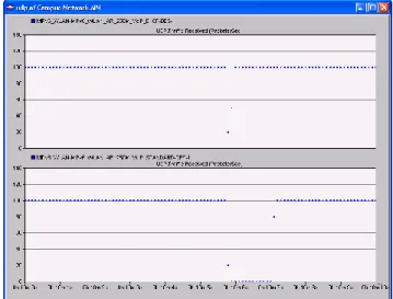
In terms of packet loss with the E-HCF approach, packets can be stored into a buffer during the handover (see subsection II-B). Figure 6 illustrates the comparison of packet loss rates between the E-HCF approach and the MIPv6 standard. The upper curve represents the number of lost packets with the MIPv6 standard (38 packets received out of 100 emitted packets), whereas the bottom curve with E-HCF approach (68 packets received out of 100 emitted packets). This gives a typical 30% gain with the E-HCF approach.
Fig. 6. Comparison of loss rates between the E-HCF approach and the MIPv6 standard by simulation
IV. CONCLUSION
In order to improve the handover performance for the Mobile IPv6, this paper studies an original E-HCF approach which allows to collect and store some link and network data. Regarding the classical Mobile IPv6 handover performance, our numerical results validated by simulations show that the
E-HCF approach enables to decrease both the total handover
latency and the packet loss significantly.
We focused on the handover performance at the Network Layer. We now are interested to also improve the handover performance at the Link Layer with a ”graph” solution. Our future goal aims at improving the handover performance both at the Network Layer for the Mobile IPv6 and at the Link Layer for IEEE 802.11 networks with a cross-layer proposal.
REFERENCE S
[1] C. Perkins, ”IP Mobility support for IPv4,” RFC 3220, IETF, January 2002.
[2] D. Johnson, C. Perkins, and J.Arkko, ”Mobility Support in IPv6,” RFC 3775, June 2004.
[3] G. Z. Wei, A. Wei, K. Xu and H. Deng, ”Handover Control Function Based Handover for Mobile IPv6,” In Proceedings of Workshop of Evolution towards Next Generation Internet (ICCS 2006), University of Reading, UK, 28-31 May 2006.
[4] C. E. Perkins, Tutorial Mobile Networking through Mobile IPv4, Sun Microsystems, http://www.computer.org/internet/v2n1/ perkins.html. 2005
[5] H. Soliman, C. Castelluccia, K. Malki, and L. Bellier, ”Hierarchical Mobile IPv6 mobility management (HMIPv6),” RFC 4140, August 2005.
[6] H. Fathi, S.H. Shin, K. Kobara, and al, ”Leakage-Resilient security Architecture for Mobile IPv6 in Wireless overlay Networks,” IEEE Journal on Selected Areas in Communications, vol. 23, No. 11, pp.2182- 2193, November 2005.
[7] Wei Kuang Lai and Jung Chia Chiu, ”Improving Handoff Performance in Wireless Overlay Networks by Switching between Two-Layer IPv6 and One-Layer IPv6 Addressing,” IEEE Journal on Selected Areas in Communications, vol. 23, No. 11, pp. 2129-2137, November 2005. [8] R. Koodli, Ed. ”Fast Handovers for Mobile IPv6,” RFC 4068, July 2005. [9] H. Chaouchi and P. Antunes, ”Pre-handover Signaling for QoS Aware
Mobility Management,” International Journal of Network Management, No. 14, pp.367-374, 2004.
[10] Y. Bi, P. Iyer, ”An Integrated IP-layer Handover Solution for Next Generation IP-based Wireless Network”, IEEE Vehicular Technology Conference VTC2004-Fall, Vol. 6, pp.3950-3954, Los Angeles, USA, 2004
[11] J. Kristiansson and P. Parnes, ”Application-layer Mobility Support for Streaming Real-time Media,” Wireless Communications and Networking Conference, Vol.1, pp.268-273, Atlanta, USA, 2004.
[12] S. Kashihara, K. Iida and al, ”End-to-End Seamless Handover Using Multi-path Transmission Algorithm,” International Conference on Internet Computing 2002, IC’02, pp. 1-7, Las Vegas, USA, 2002.
[13] ”IPv6 Address Allocation and Assignment Policy,” doc no. ripe- 267, http://www.ripe.net/ripe/docs/ipv6policy. html,January 2003
[14] ”IEEE 802.11f: Recommended Practice for Multi-Vendor Access Point Interoperability via an Inter-Access Point Protocol Access Distribution Systems Supporting IEEE 802.11 Operation”, IEEE Standard 802.11, January 2003
[15] Guozhi Wei, ”Handover Optimisation using E-HCF Method for the Mobile IPv6 protocol,” thesis, University of Paris XII, France, February, 2008.
[16] J. Bournelle and M. Laurent-Marknavicius, ”Adaptation et implementa- tion de Diameter/AAA pour Mobile IPv6, ” http://www-rp.lip6. fr/dnac/5.1-bournelle-article.pdf, 2004
[17] A. Patel, K. Leung et al, ”Authentication Protocol for Mobile IPv6,” RFC 4285, January, 2006.
[18] J. Arkko, V. Devarappli and F. Dupont, ”Using IPSec to Protect Mobile IPv6 Signaling Between Mobile Nodes and Home Agents,” RFC 3776, June 2004.