HAL Id: hal-01233649
https://hal.archives-ouvertes.fr/hal-01233649
Submitted on 30 Nov 2015
HAL is a multi-disciplinary open access
archive for the deposit and dissemination of
sci-entific research documents, whether they are
pub-lished or not. The documents may come from
teaching and research institutions in France or
abroad, or from public or private research centers.
L’archive ouverte pluridisciplinaire HAL, est
destinée au dépôt et à la diffusion de documents
scientifiques de niveau recherche, publiés ou non,
émanant des établissements d’enseignement et de
recherche français ou étrangers, des laboratoires
publics ou privés.
End-Fire Antenna Arrays
Abdullah Haskou, Ala Sharaiha, Sylvain Collardey
To cite this version:
Abdullah Haskou, Ala Sharaiha, Sylvain Collardey. Design of Small Parasitic Loaded Superdirective
End-Fire Antenna Arrays. IEEE Transactions on Antennas and Propagation, Institute of Electrical
and Electronics Engineers, 2015, 63 (12), pp.1-9. �10.1109/TAP.2015.2496112�. �hal-01233649�
Design of Small Parasitic Loaded Superdirective
End-Fire Antenna Arrays
Abdullah Haskou, Ala Sharaiha, Senior Member, IEEE, and Sylvain Collardey
Abstract—This paper presents an approach for designing
par-asitic loaded superdirective antenna arrays. The array current excitation coefficients calculated based on Yaghjian method are used with the array input impedance matrix to deduce the required loads for transforming the array to a parasitic one. The proposed method’s practical limitations are studied via a parametric analysis on dipole-based arrays. It is also applied to design two- and three-element arrays based on an Electrically Small Antenna (ESA). Simulation results show a very good agree-ment between the fully-driven array’s total directivity radiation pattern and the parasitic (loaded) array’s one. Simulation results also show that the array end-fire total directivity is maximal at the design frequency. Measured results are in a very good agreement with the simulated ones.
Keywords—Superdirectivity, parasitic array, end-fire, directivity, excitation coefficients, active impedance.
I. INTRODUCTION
A
NTENNA DIRECTIVITYis a very important parameter, andhence, it has been the subject of significant research. Early works focused on the upper limits of a single antenna-and antenna arrays- directivity [1-3]. R.F. Harrington showed that, in a single antenna permitting a highest mode order of N , the directivity can attain N2 + 2N [1]. I. Uzkov demonstrated that the end-fire directivity of N closely placed isotropic radiators can attain N2 [2]. The same limit was
derived by E. N. Gilbert and S. P. Morgan in [3] and was validated by C.O. Stearns [4] and C.T. Tai [5]. Later, E.E. Altshuler et al. practically validated the method and showed a three-element fully-driven monopole-based array [6]. An interesting chapter summarizing early works on superdirective arrays is presented in [7]. On the other hand, Electrically Small Antennas (ESAs) are very attractive in novel compact wireless technologies. However, ESAs have small efficiencies and quasi-omnidirectional radiation patterns. Consequently, in recent years, a significant research was done on the design of two-element parasitic superdirective ESA arrays [8-14]. O’Donnell and Yaghjian showed that, in wire-type arrays, the parasitic array (the parasitic element being short-circuited) presents approximately the same directivity as the fully-driven one [8]. O’Donnell et al. also studied the effect of the fre-quency optimization on a parasitic two-element array [9]. The authors showed that using the parasitic element as a director can approximately achieve the same results as the fully-driven array for a limited distance range. An efficient electrically small, two-element, closely-spaced and mounted on a large
The authors are with IETR UMR CNRS 6164- Université de Rennes 1, 35042 Rennes Cedex, France. e-mail: (abdullah.haskou@univ-rennes1.fr).
Manuscript received June 18, 2015; revised January 11, 2016.
ground plane Yagi antenna was presented in [10]. Furthermore, Yaghjian et al. showed possible end-fire supergain 3D wire ESA arrays over a large ground plane [11]. In [12] a su-perdirective array of small resonant magnetic dipole elements is designed on a large ground plane. This array exhibits a high directivity with a good efficiency of 61%. Furthermore, we can note that in most of these superdirective arrays, the authors used one driven-element while short-circuiting the others to let them operate as passive director/reflector in Yagi-Uda like manner. Recently, multiple two-element compact parasitic superdirective ESA arrays were presented [13-16]. The parasitic element in [13] and [14] is open-circuited, the one in [15] is loaded with a resistor, and in [16] it is loaded with a capacitor. More recently and in analogy with Superdirectivity, the authors in [17] demonstrated that the maximal backscattering of N isotropic antennas is N2(N +1)4π 2 and they implemented a superbackscattering antenna array. This paper presents a simple approach for designing parasitic superdirective antenna arrays. This proposed method can be applied for all distances and eliminates the need for feeding and decoupling networks and does not need any frequency optimization.1
The rest of the paper is organized as follows: section II presents the proposed approach. The practical limitations are studied in section III. The application on ESAs is presented in section IV. Results are validated via measurements in section V. Finally, section VI provides some concluding remarks.
II. PROPOSEDAPPROACH
The proposed approach is as follows:
• An N-element array’s current excitation coefficients that
maximizes the directivity in a given direction can be calculated based on Yaghjian method [6] by taking into account the elements’ pattern in the array as described in [16] by:
a0n= [Hmn∗ ]−1e−jk ˆ r0rmf∗
m(θ0, ϕ0)fn(θ0, ϕ0) (1)
where fm, fn are the far-field patterns of elements m, n
and Hmn= 1 4π 2π ∑ θ=0 π ∑ ϕ=0 fm(θ, ϕ)fn∗(θ, ϕ) ejkˆr(rm−rn)sin(θ)∆(θ)∆(ϕ) (2)
1This work was done with the funding of the French National Research
Agency as part of the project "SOCRATE" and the support of the "Images et Reseaux" cluster of Brittany region, France.
• Then, the array voltage excitation coefficients vector [V]
can be calculated as follows: [V ] = [Z][I]⇔ V (n) =
N
∑
m=1
ZnmIm (3)
where [Z] is the array impedance matrix.
• Hence, the array active impedance vector [19] can be
deduced from: Zactive(n) = V (n) I(n) = Znn+ N ∑ m=1 m̸=n Znm Im In (4)
• Finally, one element can be excited while others can be
loaded to obtain the same directivity as in the case of exciting all the elements. The load value is given by:
ZL(n) =−Zactive(n) (5)
It should be noticed that the impedance of the driven element after loading the others can easily be calculated by collapsing a multi-port network to a one port. In the case of two-elements (n, m), when exiting element n and loading m, this impedance is given by:
Zin= Znn−
ZnmZmn
Zmm+ ZL(m)
(6) And in the case of three elements (l, n, m), exciting l and loading the two others, this impedance is given by:
Zin=Zll+
ZlnZnl(ZL(m)+Zmm)+ZlmZml(ZL(n)+Znn)−ZlnZnmZml−ZlmZmnZnl ZnmZmn−(ZL(n)+Znn)(ZL(m)+Zmm)
(7)
III. PRACTICALLIMITATIONS
To understand the proposed method’s practical limitations, several parametric analysis based on dipole-based arrays are performed. The unit-element used in these analysis is a dipole of length (l = 145mm) and diameter (d = 1mm). This dipole has a simulated resonance frequency around 1GHz and a quasi-omnidirectional radiation pattern with a maximum total directivity of 2.4dBi.
We consider two-, three-, and four-element arrays with an inter-element distance varying from 0.05λ to 0.5λ. For each distance, first, the array excitation coefficients to maximize the end-fire (θ = 90, ϕ = 0) directivity at 1GHz are calculated. Then, the required loads are deduced and the array is transformed to a parasitic (loaded) one. For every distance, each time a different element is excited while the others are loaded.
Fig 1(a) shows the maximum total directivity of the two-element array. The figure shows that due to the small mutual coupling, even for small distances the excitation coefficients can accurately be calculated. Hence, the theoretical limits for the antenna maximum end-fire directivity can be attained. Furthermore, the figure shows that both parasitic array con-figurations present almost the same total directivity. Fig. 1(b) shows the obtained maximum total directivity when exciting
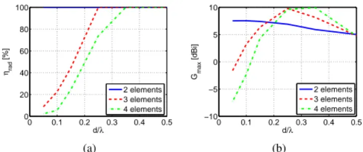
the second element and neglecting the required negative re-sistances. It can be noticed that due to the small value of the required negative resistance neglecting it has a very small effect on the antenna directivity. Fig. 6 shows that in this case, even for small distances a radiation efficiency of around 100% can be attained and the supergain can be achieved.
0 0.1 0.2 0.3 0.4 0.5 4 6 8 10 12 d/λ Dmax [dBi] Fully−driven Exciting no. 1 Exciting no. 2 (a) 0 0.1 0.2 0.3 0.4 0.5 4 6 8 10 12 d/λ Dmax [dBi] Orginal Modified (b)
Fig. 1. Two-dipole array simulated total end-fire directivity. (a) Exciting
the different elements and (b) exciting the second element and neglecting the negative resistances.
The calculated excitation coefficients of the three-element array are given in Fig. 2. The calculated required loads given in Fig. 3 shows that, for small distances, two small negative resistances are required. As the distance increases, the value of the required negative resistances also increases and starting from 0.25λ three negative resistances are required. As for the required reactances, they are of capacitor nature with an increasing value with the distance. Fig. 4(a) shows the maximum directivity versus the inter-element distance. The figure shows that for small distances the maximum theoretical directivity cannot be attained. This is due to the high coupling in this case that results to a high sensitivity of the total radiation pattern to the excitation coefficients as is well described in [6]. The figure also shows that the different parasitic arrays achieve almost the same results as the fully driven one. Fig. 4(b) shows the obtained maximum total directivity exciting the second element and neglecting the required negative resis-tances. It can be noticed that for small distances, neglecting the small negative resistance has a very limited effect on the antenna directivity. However, as the distance increases, due to neglecting two considerable negative resistances, the directivity degradation becomes more important. Finally, Fig. 6 shows the array simulated radiation efficiency in this case. Due to the high mutual coupling and thus the significant ohmic loss resistances, the array has a very low radiation efficiency for small inter-element distance. However, as the distance increases the radiation efficiency also increases and around
d = 0.25λ this efficiency reaches 100%, and hence, not only
0 0.1 0.2 0.3 0.4 0.5 0.5 1 1.5 2 2.5 d/λ |An | [A] n=1 n=2 n=3 (a) 0 0.1 0.2 0.3 0.4 −200 −150 −100 −50 0 50 100 d/λ φAn [ o] n=1 n=2 n=3 (b)
Fig. 2. Three-dipole array calculated excitation coefficients. (a) Magnitude
and (b) phase. 0 0.1 0.2 0.3 0.4 0.5 −150 −100 −50 0 50 d/λ Rload [ Ω ] R 1 R 2 R 3 (a) 0 0.1 0.2 0.3 0.4 0.5 −150 −100 −50 0 50 d/λ Xload [ Ω ] X 1 X 2 X 3 (b)
Fig. 3. Three-dipole array calculated required loads. (a) Resistance and (b)
reactance. 0 0.1 0.2 0.3 0.4 0.5 4 6 8 10 12 d/λ Dmax [dBi] Fully−driven Exciting no. 1 Exciting no. 2 Exciting no. 3 (a) 0 0.1 0.2 0.3 0.4 0.5 4 6 8 10 12 d/λ Dmax [dBi] Orginal Modified (b)
Fig. 4. Three-dipole array simulated total end-fire directivity. (a) Exciting
the different elements and (b) exciting the second element and neglecting the negative resistances.
Fig 5(a) shows the obtained directivity of the four-element array. The figure shows that this array presents approximately the same directivity as the three-element one. This is due to the high sensitivity of the antenna directivity to the excitation coefficients as the number of the elements increases as shown in [20]. The figure also shows a considerable difference between the antenna directivity exciting the different elements. This is also due to the high sensitivity to the excitation coefficients. Fig. 5(b) shows the obtained maximum total directivity when exciting the second element and neglecting the required negative resistances. Fig. 6 shows that in this case, even for relatively high distances the array has a very low radiation efficiency, and hence, the supergain cannot be achieved. The antenna radiation efficiency reaches 100% when the inter-element distance passes 0.3λ.
0 0.1 0.2 0.3 0.4 0.5 4 6 8 10 12 d/λ Dmax [dBi] Fully−driven Exciting no. 1 Exciting no. 2 Exciting no. 3 Exciting no. 4 (a) 0 0.1 0.2 0.3 0.4 0.5 4 6 8 10 12 d/λ Dmax [dBi] Orginal Modified (b)
Fig. 5. Four-dipole array simulated total end-fire directivity. (a) Exciting
the different elements and (b) exciting the second element and neglecting the negative resistances. 0 0.1 0.2 0.3 0.4 0.5 0 20 40 60 80 100 d/λ ηrad [%] 2 elements 3 elements 4 elements (a) 0 0.1 0.2 0.3 0.4 0.5 −10 −5 0 5 10 d/λ Gmax [dBi] 2 elements 3 elements 4 elements (b)
Fig. 6. Simulated parameters of the different arrays when exciting the second element and neglecting the negative resistances. (a) radiation efficiency and (b) total gain in dB.
From this study it can be concluded that the proposed method is limited by the sensitivity in calculating the exci-tation coefficients and the attainable radiation efficiency as the number of the elements increases and the inter-element decreases. The results reveal that this sensitivity to the ex-citation coefficients do not decrease the antenna maximum end-fire directivity by more than 1dBi for two-, three- and four-element arrays if the spacing of the array elements is larger than about 0.05λ, 0.1λ and 0.2λ, respectively. However, once the excitation coefficients are calculated, the proposed loading method is not limited by the number of the elements nor by the inter-element distance. This analysis also showed that, due to practical limits and difficulties, the conception of superdirective arrays is a compromise between array’s directivity, radiation efficiency and size (number of elements and inter-element spacing).
IV. APPLICATION ONESAS
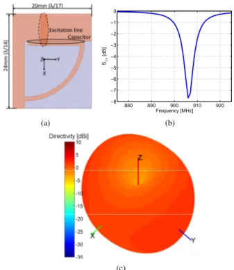
The proposed method was used to design different ESA-based planar arrays with an inter-element distance of 34.3mm(0.1λ). The unit-element used in these arrays is a miniaturized printed half-loop antenna. The loop is shorted to the ground plane and loaded by a capacitance to reduce its dimensions. This capacitance is realized by two metallic strips separated by a gap of 0.1mm. The antenna is fed by coupling through a microstrip line located on the bottom side. The antenna is printed on a 0.8mm-thick Rogers RO4003 substrate and its dimensions are 24mm×20mm corresponding
to 14λ×17λ for a resonance frequency of 906M Hz. The antenna has an impedance bandwidth of 2.6M Hz.2 It has a simulated total directivity of 2.2dBi and radiation efficiency of 32%. Fig. 7(a) shows the antenna geometry and dimensions, Fig. 7(b) shows its input reflection coefficient magnitude and Fig. 7(c) shows its quasi-omnidirectional total directivity radiation pattern. (a) 880 890 900 910 920 −8 −7 −6 −5 −4 −3 −2 −1 0 Frequency [MHz] S1 1 [dB] (b) (c)
Fig. 7. The miniaturized unit-element. (a) Geometry and dimensions, (b)
simulated input reflection coefficient magnitude and (c) simulated 3D total directivity radiation pattern.
A. Two-Element Array
Fig. 8(a) shows this array’s geometry and dimensions. Fig. 8(b) shows that, due to mutual coupling, the antenna resonance frequency is shifted to 905M Hz, hence, the array is designed for this frequency with a size factor (ka = 0.56). Exciting the second element with a current of 1.32ej150.4o relative
to the first one, a maximum total directivity of 7.1dBi is achieved at the same frequency. In the parasitic array, where the first element is excited while the second one is loaded with a capacitor of 5.1pF , a maximum directivity in the end-fire direction of 7dBi is achieved. This directivity is 5.44dBi greater than Harrington’s normal directivity limit [1] for an antenna with the same size factor. Due to the limited efficiency of the unit-element and the mutual coupling, the array radiation efficiency decreases to 7.1%. Fig. 9 shows the simulated 3D total directivity radiation patterns for both the fully-driven array and the parasitic one. Fig. 10 shows both the driven and parasitic array’s 2D radiation patterns in
2 The (S
11 < −6dB) criterion will be considered for the impedance
bandwidth, while Dmax− 1dB will be considered for the directivity one.
horizontal and vertical planes (XOY and YOZ). The figure shows a very good agreement between the two cases. In the fully driven array, the Half-Power Beamwidth (HPBW) in horizontal and vertical planes are respectively 105o and 80o
and the Front to Back Ratio (FBR) is equal to 7.8dB. In the parasitic array, the HPBW in horizontal and vertical planes are respectively 110o and 80o and the FBR is equal to 9dB. Fig. 11 shows that the parasitic array end-fire total directivity (D(θ=90o,ϕ=270o)) is maximal around the antenna resonance of
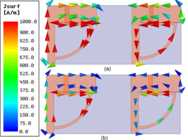
905M Hz. The array has an impedance bandwidth of 2.1M Hz and an adjacent resonance frequency appears. The array has a directivity bandwidth of 1.7M Hz. Finally Fig. 12 shows that the surface current distribution of parasitic array is similar to the one of the fully-driven array (the same color range will be used for the upcoming arrays). Furthermore, as expected, we can note that the current on the two elements is out of phase.
(a) 880 890 900 910 920 −20 −15 −10 −5 0 Frequency [MHz] Sii [dB] S11 S22 (b)
Fig. 8. Two-element array. (a) Geometry and dimensions and (b) simulated
input reflection coefficient magnitude.
Fig. 9. Two-element array’s simulated 3D total directivity radiation pattern.
−20 −10 0 10 30 210 60 240 90 270 120 300 150 330 180 0 φ [°]
Directivity [dBi] Driven
Parasitic (a) −20 −10 0 10 30 210 60 240 90 270 120 300 150 330 180 0 θ [°]
Directivity [dBi] Driven
Parasitic
(b)
Fig. 10. Two-element array’s simulated 2D total directivity radiation patterns. (a) Horizontal plane and (b) vertical plane.
880 890 900 910 920 −10 −5 0 Frequency [MHz] S11 [dB] 880 890 900 910 920 0 2 4 6 8 10
End−Fire Directivity [dBi]
Fig. 11. Parasitic two-element array’s simulated input reflection coefficient
magnitude and end-fire total directivity.
(a)
(b)
Fig. 12. Two-element array’s simulated surface current distribution.(a) Fully-driven array and (b) parasitic one.
B. Two-Element Array on a PCB
In [21] we proposed introducing a slot in the PCB in order to maintain end-fire superdirectivity. This approach was used to integrate the aforementioned array in a PCB with total dimensions of 110× 70mm2. Fig. 13(a) shows the antenna
geometry and dimensions. The slot size of 5mm is chosen to obtain a good compromise between the obtained maximum directivity and radiation efficiency. Fig. 13(b) shows the input reflection coefficient magnitude of both elements. We can note
that, in this case, and due to the mutual coupling and the big size of the ground plane, the antenna resonance frequency is shifted to 866M Hz. Hence, the array is designed for this frequency with a size factor (ka = 1.18). Exciting the second element with a current of 0.55e−j101.6o relative the first one, a maximum total directivity of 7.2dBi is achieved. In the parasitic array, where the second element is excited while the first one is loaded with an inductor of 4.35nH, a max-imum directivity of 7.2dBi is also achieved.This directivity is 1.44dBi greater than Harrington’s normal directivity limit for an antenna with the same size factor. Fig.14 illustrates the 3D total directivity radiation patterns and Fig. 15 shows 2D radiation patterns in horizontal and vertical planes. We can see an excellent agreement between the two cases where the HPBW in horizontal and vertical planes are respectively 74◦ and 110◦. The fully-driven array’s FBR is about 7.2dB while the parasitic array’s one is about 8.4dB. As in the previous scenario, Fig. 16 shows that the parasitic array end-fire total directivity (D(θ=90o,ϕ=90o)) is maximal around the
antenna resonance of 866M Hz. The array has an impedance bandwidth of 2M Hz a directivity bandwidth of 5.7M Hz. In this case, we can monitor the effect of ground plane in ESAs that contributes to the antenna radiation where the antenna radiation efficiency is increased to 62%. Finally, Fig. 17 shows shows the same surface current distribution in the fully-driven and the parasitic array.
(a) 830 840 850 860 870 880 890 900 −14 −12 −10 −8 −6 −4 −2 0 Frequency [MHz] Sii [dB] S11 S22 (b)
Fig. 13. Two-element array mounted on a PCB. (a) Geometry and dimensions and (b) simulated input reflection coefficient magnitude.
Fig. 14. Two-element array mounted on a PCB’s simulated 3D total directivity radiation pattern. (a) Fully-driven array and (b) parasitic one.
−20 −10 0 10 30 210 60 240 90 270 120 300 150 330 180 0 φ [°] Directivity [dBi] Driven Parasitic (a) −20 −10 0 10 30 210 60 240 90 270 120 300 150 330 180 0 θ [°] Directivity [dBi] Driven Parasitic (b)
Fig. 15. Two-element array mounted on a PCB’s simulated 2D total directivity radiation patterns. (a) Horizontal plane and (b) vertical plane.
830 840 850 860 870 880 890 900 −10 −5 0 Frequency [MHz] S11 [dB] 830 840 850 860 870 880 890 9000 2 4 6 8 10
End−Fire Directivity [dBi]
Fig. 16. Parasitic two-element array mounted on a PCB’s simulated input
reflection coefficient magnitude and end-fire total directivity.
(a) (b)
Fig. 17. Two-element array mounted on a PCB’s simulated surface current
distribution.(a) Fully-driven array and (b) parasitic one.
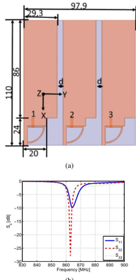
C. Three-Element Array on a PCB
The proposed method was used again to design a three-element array mounted on a PCB as shown in Fig. 18(a). Fig. 18(b) gives the input reflection coefficient magnitude of the three elements. It can be noticed that, due to the higher mutual coupling, the array resonance is shifted to 863M Hz. Hence, the array is designed for this frequency with a size factor (ka = 1.33). The PCB slot size is chosen to be 5mm because it
presents the best compromise between the antenna directivity and radiation efficiency as it can be seen in Fig. 19.
(a) 830 840 850 860 870 880 890 900 −30 −25 −20 −15 −10 −5 0 Frequency [MHz] Sii [dB] S11 S22 S33 (b)
Fig. 18. Three-element array mounted on a PCB. (a) Geometry and
dimensions and (b) simulated input reflection coefficient magnitude.
2 4 6 8 8 8.5 9 9.5 10 Dmax [dBi] d [cm] Driven Parasitic (a) 2 4 6 8 7 7.5 8 8.5 9 ηrad [%] d [cm] (b)
Fig. 19. The slot size (d) effect on: (a) the maximum directivity and (b)
radiation efficiency.
Exciting the second- and third-element with a current of 1.46e−j156.6o and 0.51ej28.5o relative to the first one, a max-imum total directivity of 9.4dBi is achieved. In the parasitic array, the first and third elements are respectively loaded with 7.6Ω//11.4pF and 3.74pF and it achieves a maximum total directivity of 9dBi. This directivity is 2.53dBi greater than Harrington’s normal directivity limit for an antenna with the same size factor. Fig. 20 shows the 3D total directivity radiation patterns and Fig. 21 shows the 2D radiation patterns
in horizontal and vertical planes. The figures show a good agreement between the two cases. For both case, the HPBWs in horizontal and vertical planes are respectively 58◦ and 72◦. The fully-driven array’s FBR is about 15.4dB while the parasitic array’s one is about 14.1dB. Fig. 22 shows the same trend as in the two previous scenarios. The antenna has an impedance bandwidth of 2.5M Hz and a directivity bandwidth of 2.6M Hz. Due to the increment in the mutual coupling, the antenna presents a radiation efficiency of 8.7%. This efficiency can be improved by increasing the inter-elements distance as discussed in section III. If we increase the spacing between elements from 0.1λ to 0.2λ, the radiation efficiency attains 53%. However, this gain in the antenna performance comes with a significant increment in the antenna dimensions (from
110× 98mm2 to 110× 166.4mm2). So, there is necessary
a compromise to be done between the antenna- dimensions, -achieved directivity and -radiation efficiency. Fig. 23 shows again a good agreement between the surface current distribu-tion of the fully-driven and the parasitic array. Finally, this an-tenna is significantly smaller than a Yagi-Uda anan-tenna covering the same frequency band and with the same directivity which dimensions are about 500 × 152mm2 [22]. Moreover, this
antenna is easier to integrate in the communications systems.
(a) (b)
Fig. 20. Three-element array mounted on a PCB’s simulated 3D total
directivity radiation pattern. (a) Fully-driven array and (b) parasitic one.
−20 −10 0 10 30 210 60 240 90 270 120 300 150 330 180 0 φ [°] Directivity [dBi] Driven Parasitic (a) −20 −10 0 10 30 210 60 240 90 270 120 300 150 330 180 0 θ [°] Directivity [dBi] Driven Parasitic (b)
Fig. 21. Three-element array mounted on a PCB’s simulated 2D total
directivity radiation patterns. (a) Horizontal plane and (b) vertical plane.
830 840 850 860 870 880 890 900 −15 −10 −5 0 S11 [dB] Frequency [MHz] 830 840 850 860 870 880 890 9000 2 4 6 8 10 12
End−Fire Directivity [dBi]
Fig. 22. Parasitic three-element array mounted on a PCB’s simulated input
reflection coefficient magnitude and end-fire total directivity.
(a) (b)
Fig. 23. Three-element array mounted on a PCB’s simulated surface current
distribution.(a) Fully-driven array and (b) parasitic one.
It should be noted that, in all cases, the very small difference between the fully driven-array’s radiation pattern and the parasitic one is due to neglecting a required small negative resistance.
V. RESULTSVALIDATION VIAMEASUREMENTS
A prototype of the second array was fabricated and mea-sured for results validation (Fig. 24(a)) [23]. Fig. 24(b) shows the antenna measured input reflection coefficient magnitude. The measured resonance frequency is 901M Hz (a frequency shift of 4.2%). This shift is probably due to the cable and the connector effects as well as the dispersion of the commercial SMD loads. The antenna bandwidth is 3.6M Hz. The antenna 3D far-field radiation pattern was measured in SATIMO star-gate (SG 32) near-field measurement system. The measured 3D total directivity radiation pattern at the resonance frequency is given in Fig. 24(c). The figure shows a superdirective radiation pattern with a maximum total directivity of 6.8dBi. The array measured 2D total directivity radiation patterns are given in Fig. 25. The measured HPBW in horizontal and vertical planes are respectively 72◦and 112◦and the FBR is equal to 7.2dB. This is in a very good agreement with the simulated results. The very small difference can be attributed to the SMD components, the coaxial cable radiation effect, and the measuring system and environment. Fig. 26(a) shows that the antenna measured total directivity is maximal at the measured
resonance frequency. The antenna directivity bandwidth is around 8M Hz. The antenna efficiency was measured in a reverberation chamber with a tolerance of 15% (due to the incertitude in the reference antenna’s efficiency) [24]. The antenna presents a measured radiation efficiency of about 70% (Fig. 26(b)). (a) 750 800 850 900 950 1000 −12 −10 −8 −6 −4 −2 0 Frequency [MHz] S11 [dB] Simulated Measured (b) (c)
Fig. 24. Two-element array mounted on a PCB. (a) A photograph of
the prototype, (b) measured input reflection coefficient magnitude and (c) measured 3D total directivity radiation pattern.
−20 −10 0 10 30 210 60 240 90 270 120 300 150 330 180 0 φ [°] Directivity [dBi] Simulation Measurement (a) −20 −10 0 10 30 210 60 240 90 270 120 300 150 330 180 0 θ [°] Directivity [dBi] Simulation Measurement (b)
Fig. 25. Two-element array mounted on a PCB’s measured 2D total directivity radiation patterns. (a) Horizontal plane and (b) vertical plane.
8503 900 950 3.5 4 4.5 5 5.5 6 6.5 7 Frequency [MHz] Dmax [dBi] (a) 750 800 850 900 950 1000 −10 −5 0 S11 [dB] Frequency [MHz] 750 800 850 900 950 10000 25 50 75 100 Efficiency [%] S11 ηrad ηtot (b)
Fig. 26. Two-element array mounted on a PCB’s measured parameters. (a)
Maximum total directivity and (b) efficiency.
VI. CONCLUSION
In this paper, a design approach for parasitic superdirective antenna arrays was presented. A parametric analysis on dipole-based arrays showed that the loading method is not limited by the number of the elements nor by the inter-element distance. This analysis also showed that the conception of parasitic superdirective arrays is a compromise between the directivity, efficiency and the antenna size (the number of the elements and the inter-element spacing). The proposed approach was also used to design two- and three-element ESA-based arrays. In all cases, the parasitic array’s simulated total directivity radiation pattern was very close to the fully-driven array’s one. Furthermore, the end-fire directivity was maximal at the design frequency. The measured results were in a very good agreement with the simulated ones.
REFERENCES
[1] R. F. Harrington, "On the Gain and Beamwidth of Directional Antennas",
IRE Transactions on Antennas and Propagation, pp. 219-225, July 1958.
[2] I. Uzkov, "An Approach to the Problem of Optimum Directive Antennae
Design", Comptes rendues (Doklady) de l’académie des sciences de l’URSS, Vol. 53, No. 1, 1946.
[3] E. N. Gilbert, and S. P. Morgan, "Optimum Design of Directive Antenna
Arrays Subject to Random Variations", Bell System Technical Journal, Vol. 34, pp. 637-663, May 1955.
[4] C. O. Stearns, "Computer Performance of Moderate Size, Super-Gain
Antennas", NBS Report 6797, 5 September, 1961.
[5] C. T. Tai, "The Optimum Directivity of Uniformly Spaced Broadside
Arrays of Dipoles", IEEE Transactions on Antennas and Propagation, Vol. 12, pp. 447-454, July 1964.
[6] E. E. Altshuler, T. H. O’Donnell, A.D. Yaghjian, and S. R. Best, "A
Monopole Superdirective Array", IEEE Transactions on Antennas and Propagation, Vol. 53, No. 8, pp. 2653-2661, August 2005.
[7] R. C. Hansen, and R. E. Collin, "Small Antenna Handbook", John Wiley & Sons Incorporation, Hoboken, New Jersey, 2011.
[8] T. H. O’Donnell, and A. D. Yaghjian, "Electrically Small Superdirective
Arrays Using Parasitic Elements", IEEE Antennas and Propagation Society International Symposium 2006, pp. 3111,3114, 9-14 July 2006.
[9] T. H. O’Donnell, A. D. Yaghjian, and E. E Altshuler, "Frequency
Optimization of Parasitic Superdirective Two Element Arrays", IEEE Antennas and Propagation Society International Symposium 2007, pp. 3932,3935, 9-15 June 2007.
[10] S. Lim, and H. Ling, "Design of Electrically Small Yagi Antenna",
Electronics Letters, Vol. 43, No. 5, pp.3-4, 1 March 2007.
[11] A. D. Yaghjian, T. H. O’Donnell, E. E. Altshuler, and S. R. Best
"Electrically Small Supergain End-Fire Arrays", Radio Science, Vol. 43, 2008.
[12] O. S. Kim, S. Pivnenko, and O. Breinbjerg, "Superdirective Magnetic
Dipole Array as a First-Order Probe for Spherical Near-Field An-tenna Measurements", IEEE Transactions on AnAn-tennas and Propagation, Vol. 60, No. 10, pp.4670-4676, October 2012.
[13] B. Sentucq, A. Sharaiha, and S. Collardey, "Superdirective Compact
Parasitic Array of Metamaterial-Inspired Electrically Small Antenna", International Workshop on Antenna Technology (iWAT), pp. 269,272, 4-6 March 2013.
[14] B. Sentucq, A. Sharaiha, and S. Collardey, "Superdirective
Metamaterial-Inspired Electrically Small Antenna Arrays", 7th European Conference on Antennas and Propagation (EuCAP2013), pp.151,155, 8-12 April 2013.
[15] M. Pigeon, A. Sharaiha, and S. Collardey, "Miniature and Superdirective
Two Elements Endfire Antenna Array", 8th European Conference on Antennas and Propagation (EuCAP 2014), 6-11 April 2014.
[16] A. Haskou, A. Sharaiha, S. Collardey, M. Pigeon, and K. Mahdjoubi,
"A Design Methodology for Electrically Small Superdirective Antenna Arrays", 2014 Loughborough Antennas and Propagation Conference (LAPC 2014), 10-11 November 2014.
[17] I. Liberal, I. Ederra, R. Gonzalo, and R. W. Ziolkowski,
"Super-backscattering Antenna Arrays", IEEE Transactions on Antennas and Propagation, Vol. 63, No. 5, pp.2011-2021, May 2015.
[18] ANSYS HFSS, Pittsburg, PA 15219, USA.
[19] C. A. Balanis, "Antennas Theory: Analysis and Design", John Wiley
and Sons Incorporation, Third edition, New York, 2005.
[20] M. Uzsoky, and L. Solymar, "Theory of Super-Directive Linear Arrays",
Acta Physica Academiae Scientiarum Hungaricae, Vol. 6, pp.185205, 1956.
[21] A. Haskou, A. Sharaiha, and S. Collardey, "Integrating Superdirective
Electrically Small Antenna Arrays in PCBs", IEEE Antennas and Wire-less Propagation Letters, Vol. PP, No. 99, pp.1,1.
[22]
http://www.titanwirelessonline.com/v/vspfiles/assets/images/at-ya-9%20data%20sheet.pdf
[23] A. Haskou, A. Sharaiha, and S. Collardey, "On Measuring
Superdirec-tive Electrically Small Antenna Arrays", 2015 International Workshop on Antenna and Technology (iWAT 2015), 4-6 March 2015.
[24] G. Le Fur, C. Lemoine, P. Besnier, A. Sharaiha, "Performances of
UWB Wheeler Cap and Reverberation Chamber to Carry Out Efficiency Measurements of Narrowband Antennas", IEEE Antennas and Wireless Propagation Letters, Vol. 8, pp.332,335, 2009.
Abdullah Haskou Was born in Aleppo, Syria in
1985. He received a B.E. in communications engi-neering from Aleppo University in 2007. He worked as an instructor at Aleppo University in both mi-crowaves and antennas laboratories from 2009 to 2011. He graduated with a GPA of 92.57% from Master’s program in electrical and computer en-gineering department, the American University of Beirut, Lebanon in 2013. During the Master’s pro-gram he was a graduate assistant in both electronics and computer organization laboratories. He was also a research assistant in Electromagnetics and Radio Frequencies (EMRF) research group. In summer 2013, he did a research internship on Orbital Angular Momentum (OAM) mode estimation at Institut d’Electronique et de Télécommunications de Rennes (IETR), France. He is currently working at IETR toward a PhD degree. His research interests are mainly in electromag-netics and radio frequencies field including antennas- and RF circuits- design.
Ala Sharaihareceived the Ph.D. and Habilitation à
Diriger la Recherche (HDR) degrees in telecommu-nication from the University of Rennes 1, France, in 1990 and 2001 respectively. Currently, he is a Full Professor at the University of Rennes 1, Rennes, France and the Co-Head of the "Complex Radiation Systems" Team in the "Antennas and Microwave De-vices" Department. His main research activities in-clude small antennas, broadband and UWB antennas, reconfigurable antennas, printed spiral and helical antennas, antennas for mobile communications, etc. Conducted and involved in more than 20 industrial and collaborative projects. Prof. Sharaiha has published more than 300 journal and conference papers, concerning antenna theory, analysis, design and measurements, and he holds 12 patents. His published works have been cited over 700 times in Google Scholar. He has graduated/mentored over 30 Ph.D. students/post-docs, and co-authored with them.
He is presently a member of the European School of Antennas Board and a member of the small antennas working group of the European Association on Antennas and Propagation (EuRAAP). He is a senior member of the IEEE and is a reviewer for the IEEE APS, IEEE AWPL, the IET Letters and the IET Microwave Antennas Propagation. He was the conference Chairman of the 11th International Canadian Conference ANTEM (Antenna Technology and Applied Electro- Magnetics), held at Saint-Malo in France, 2005.
Sylvain Collardey received his PhD Degree in
telecommunication from the University of Rennes 1, France, in 2002. He was graduated in Electronics and Telecommunication Engineering at the University of Rennes 1 in the year 1998. Currently, he is associate professor at the University of Rennes 1 and involved as researcher in the Antennas and Microwaves group at the Institute of Electronic Telecommunication of Rennes (IETR). His current research interests in-clude the characterization and development of small antennas, EBG materials and metamaterials, and RFID. He has published more than hundred revue papers and conference communications.