HAL Id: hal-00872096
https://hal.archives-ouvertes.fr/hal-00872096
Submitted on 11 Oct 2013
HAL is a multi-disciplinary open access
archive for the deposit and dissemination of
sci-entific research documents, whether they are
pub-lished or not. The documents may come from
teaching and research institutions in France or
abroad, or from public or private research centers.
L’archive ouverte pluridisciplinaire HAL, est
destinée au dépôt et à la diffusion de documents
scientifiques de niveau recherche, publiés ou non,
émanant des établissements d’enseignement et de
recherche français ou étrangers, des laboratoires
publics ou privés.
among assembly constraints in assembly sequence
planning.
Christophe Perrard, Eric Bonjour
To cite this version:
Christophe Perrard, Eric Bonjour. Unification of the a priori inconsistencies checking among
assem-bly constraints in assemassem-bly sequence planning.. International Journal of Advanced Manufacturing
Technology, Springer Verlag, 2013, pp.1-17. �10.1007/s00170-013-4885-1�. �hal-00872096�
Unification of the a priori inconsistencies checking among assembly
constraints in assembly sequence planning
!"#$%&'(")*+)##,#-* ./0*!102*3456*728/*9)(,#&:);&<* .;$=)#%$&>*'?*@#,;A")B!':&C** @D/EFB2E*G;%&$&H&)<* 86<*#H)*7I,$;*2,=,#><* 8JKKK*L)%,;M';<*@#,;A)* )B:,$IN*A"#$%&'(")O()##,#-P?):&'B%&O?# D#$A*L';Q'H#* D0+G*RDSH$()*-)*0)A")#A")*%H#*I)%*+#'A)%%H%*G;;'=,&$?%T<* .;$=)#%$&>*'?*U'##,$;)<* V*#H)*L,%&$);*U)(,W)*L+365<* J6K4K*1,;A>*!)-)X<*@#,;A)* )B:,$IN*)#$AOY';Q'H#PH;$=BI'##,$;)O?#
Sequence planning generation is an important problem in assembly line design. A good assembly sequence can help to reduce the cost and time of the manufacturing process. This paper focuses on assembly sequence planning (ASP) known as a hard combinatorial optimization problem. Although the ASP problem has been tackled via even more sophisticated optimization techniques, these techniques are often inefficient for proposing feasible assembly sequences that satisfy the assembly planners’ preferences.
This paper presents an approach that makes easier to check the validity of operations in assembly process. It is based on a model of the assembly planners’ preferences by means of strategic constraints. It helps to check a
priori the consistency of the assembly constraints (strategic an operative constraints) given by the assembly system designers before and while running an assembly plan generation algorithm. This approach reduces the solution space significantly.
A case study is presented to demonstrate the relevance of the proposed approach.
Keywords: Assembly plans generation; assembly sequences; assembly strategy; strategic constraints; assembly precedence graph, interference matrices
The aim of Assembly Sequence Planning (ASP) is to determine the arrangement of assembly operations on the assembly line. Generally, ASP consists of two major activities: assembly modelling and assembly sequence generation [Hui 07]. Assembly sequence generation of complex products is a difficult problem, because the size of the search space is exponentially proportional to the number of components that form the product. Consequently, ASP is a typical combinatorial explosion problem [Henrioud 91] [Marian 03] [Gu 08] which has been proved to be NP-hard.
For the last ten years, a great attention has been drawn to the development of complex algorithms that exploit specific meta-heuristics in order to solve the ASP problem [Wang 09]. The traditional solving approach is structured as follows: representation, generation, feasibility, and selection [Gottipolu 03]. Much research has been done on this basis [Bai 05] [Wang 09]. Related works generate possible assembly sequences, check assembly feasibility (for instance, for geometric feasibility [Hui 07]) and finally try to identify the final choice by the optimization of cost or time criteria.
However, the previous optimization approaches often fail to represent product designer’s and assembly planner’s preferences, so that the resulting assembly sequences are not fully satisfactory from their point of view.
Few authors have mentioned the interest of strategic constraints [Henrioud 89] [Homem 91] [Delchambre 92] [Gottipolu 03] [Perrard 12] that come from either technical or industrial concerns. These constraints are added to other design data that describe the product structure (product model). They are issued from an analysis that is performed by a team made of product designers and assembly planners [Demoly 11]. Assembly planners need assembly plans (or sequences) to define the flows of components throughout the assembly system. Surprisingly, few ASP algorithms based on strategic constraints have been developed whereas they make it possible to significantly reduce the research space of assembly sequence generation algorithms (decrease in the number of sequences) and to better satisfy the assembly system designers [Martinez 09].
A recent paper [Perrard 12] described a new approach allowing a priori checking of the inconsistencies among strategic constraints within an assembly strategy that is given by the assembly system designers. This checking is said a priori because it is made before running the whole ASP program. This former paper presented different types of strategic constraints.
The present paper is an extension of the former paper. It demonstrates the interest of this new approach in the assembly plan generation problem. Usually when researchers propose to deal with strategic constraints during
the generation of optimal assembly sequences, they develop multiple specific programs to check the feasibility of candidate sequences in regard of each strategic constraint.
In this paper, we propose to make the program writing easier by integrating all checking programs into one global program. This improvement makes it possible to reduce the time necessary to write the checking program and help to check the consistency of each candidate sequence quickly and globally. The proposed unified checking will facilitate the integration of strategic constraints in future optimization algorithms because it makes it possible to quickly check the validity of a potential operation in regard of the assembly planners’ preferences (this operation may be generated by cross-over in a genetic algorithm).
This paper addresses two main contributions:
- unification/merging of the representations of assembly data (product model, strategic constraints, interference constraints) in a unique Boolean equation
- integration of the a priori inconsistencies checking between these data into the ASP. Another interest of these proposals is the simplification of the programming of the ASP algorithm. This paper is composed of four main sections:
- The description of a case study that will be applied to illustrate state of the art concepts and proposal concepts along the paper.
- A brief review of classical models used by ASP and the review of related methods.
- The adaptation of the a priori checking of inconsistencies among strategic constraints to the problem of ASP to check operations, and the description of the reorganization of the stages inside ASP. Then, a proposal will be made, in order to allow an efficient management of the strategic constraints. It will be shown to be a huge simplification of traditional programs.
- finally, in the last section, assembly operations issued from the case study are matched to demonstrate the effectiveness of the proposal.
Notations are given in Table 1.
- PF the end product
- Cp set of the c (elementary) components to assemble. Cp={ c1,…cn }
- VA set of added values to provide to Cp in order to obtain the end
product. VA={va1,…vam} ; VA= L ! S ! A where:
- L set of liaisons of PF. It is a sub-set of VA
- S set of attachments of PF. It is a sub-set of VA
- A set of added requirements of PF. It is a sub-set of VA
- va an element of VA
- "OO’ the complement of sub-set O’ inside set O
- P(va1 , va2) or P’(VA1 , VA2) strong anteriority constraint where
P involves added values P’ involves sets of added values - Q(va1 , va2) or Q’(VA1 , VA2) weak anteriority constraint
- R(va1 , va2) or R’(VA1 , VA2) anteriority constraint, either weak or strong
- S(va1 , va2) or S’(VA1 , VA2) simultaneity constraint
- ASP assembly sequence planning
- OGC operative geometric constraint
Table 1. Notations
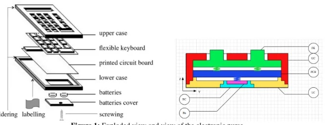
In order to highlight the main concepts, we propose to illustrate this paper with a case study. This example is issued from an industrial technology transfer application. An electronic purse (Figure 1) is composed by six elementary components: upper case (UC), flexible keyboard (FK), printed circuit board (PCB), lower case (LC), batteries (Ba), batteries cover (BC). Its assembly implies the performing of eight liaisons and four other added values: soldering (So), screwing (Sc), final check (FC), labelling (La).
Figure 1: Exploded view and view of the electronic purse
3. State of the art: Models
related to assembly sequence
generation
Key concepts related to assembly plan (or sequence) generation are presented in this section. They have been mostly described in [Henrioud 89]. More recently, [Jimenez 11] gives a large review of the literature in ASP.
3.1. Product model
The end product may be seen, according to the assembly point of view, as the mating of two sets: - Cp, that represents the set of the c (elementary) components ci to be assembled
- VA, that represents the set of values vai to add to these components in order to obtain the end product.
An element of VA is usually called ‘added value’. Then the product can be represented by the couple (Cp, VA) The added values have the function of:
- structuration of the components together (it is the set of geometrical liaisons L) - perennialization of this structure (it is the set of attachments S)
- satisfaction of particular product requirements (it is the set of auxiliary added values A, like milling, forming, checks, cleanings,…).
Then, VA is the union of L, S and A.
To perform a given added value of VA, specific conditions have to be satisfied, like the presence of some components and the previous performing of other added values of VA. Then, it is possible to represent the added values and their associated relationships by an oriented graph. We propose to call it ‘precedence graph of added values’. A precedence (or anteriority) between two added values va1 and va2 describes the need to perform va1 before va2. Of course, a given precedence graph may represent a great amount of valid sequences to assemble the product.
Liaison graph and other non geometric added values
Cp={UC, FK, PCB, LC, Ba, BC} VA = L ! S ! A, with:
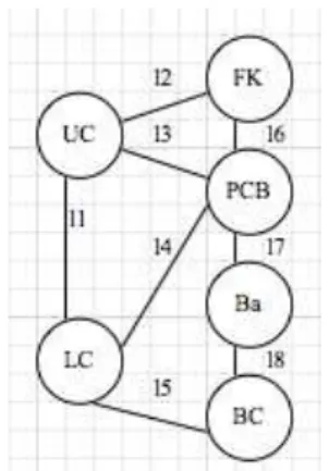
L={l1, l2, l3, l4, l5, l6, l7, l8} where (see Figure 2): l1 = (UC, LC) l2 = (UC, FK) l3 = (UC, PCB) l4 = (LC, PCB) l5 = (LC, BC) l6 = (FK, PCB) l7 = (PCB, Ba) l8 = (Ba, BC)
Figure 2: Liaison graph of the electronic purse
S={So, Sc} where:
So is the soldering of UC and LC; it may be expressed by: So=({UC, FK, PCB, LC}, {l1, l2, l3, l4, l6}) Sc is the screwing of LC and BC:
Sc=({LC, BC}, {l5}) A={FC, La} where:
FC=(Cp, {So, Sc}, #, #) La= ({LC}, #, {FC})
Precedence graph of added values
The previous model gives the set of precedence (see Figure 3): P’({ {l1, l2, l3, l4, l6}, {So})
$ P’({l5}, {Sc}) $ P’({Sc, So}, {FC}) $ P’({FC},{La})
Figure 3: Precedence graph of added values for the electronic purse issued from the product modelling
Note that, in the graph in Figure 3, liaisons l7 and l8 do not have anteriorities with other added values, according to the product model.
3.2. Description of sub-assemblies and assembly operations
A sub assembly is completely defined by: - the list of its elementary components
- the list of the added values that have been performed to form the sub-assembly. Then, each sub-assembly of a given product can be represented by a 4-tuple:
(Ci,Li,Si,Ai)
where Ci % C, Li % L, Si % S and Ai % A.
-a- -b-
Figure 4: examples of different contexts to perform the l4 liaison of the electronic purse.
It becomes fully defined if each involved assembly is described: assemblies before and the sub-assembly after the operation. To define an operation completely, one must define:
- the description of each sub-assembly (Ci,Li,Si,Ai) that is involved by the operation (before and after it),
- the sub-set of VA that is brought by the operation. Thus, an operation can be represented by a 4-tuple:
((C1,L1,S1,A1), (C2,L2,S2,A2), VAi, (C3,L3,S3,A3))
Example:
The operation described by Figure 1.b. can be represented by the 4-tuple:
(({LC},#,#,#), ({PCB, FK},{l6},#,#), ({l4}, ({LC,PCB,FK},{l4,l6},#,#)) Notes:
- the order between the first two terms of this 4-tuple doesn’t matter (at this step of the assembly process design, the concept of primary/secondary sub-assemblies is not taken into account)
- it is always possible to deduce one term of the 4-tuple from the three others (redundant information).
3.3. Assembly plan models
An assembly plan describes a particular way to assemble the elementary components in order to obtain the end product. It involves a particular set of operations. It exists different levels of description of an assembly plan:
- the most simple one, called assembly process. It only describes objects (components, produced sub-assemblies and end product), and partial order between operations to perform. These operations only describe which added values are brought to sub-assemblies.
- the most complete one, called operative diagram. It is an assembly process and all pertinent information to perform operations (objects orientation, logistic operations, used equipment and adjustments used, operative times,…)
- intermediate assembly plan description, depending on the ASP method used.
In this paper, we only deal with processes.
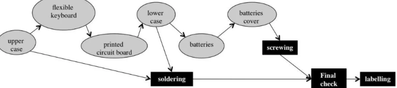
In a process, the operations are partially ordered through a tree. A process is a particular solution that respects the added value precedence graph (Figure 5). It is the less refined description level of an assembly plan.
-b- parallel process -c- linear process
Figure 5: examples of process of the electronic purse.
Usually, a process involves:
- binary operations, if they make it possible to mate two constituents. They are so-called geometric operations. A geometric operation brings one (or more) added value(s) of L. The « + » symbol indicates a multi-added values operation, like examples in Figure 3.
- unary operations, if they bring an added value to an unique constituent. This added value is unique and belongs to S ! A. The corresponding operation, so-called non geometric, is an attachment (if the added value belongs to S) or an auxiliary one (if the added value belongs to A).
- other operations that involve more than two constituents are not taken under consideration here.
Thus, a process may be represented by a binary tree, where each node represents an operation. Such a tree can be represented by:
- a set of oriented arcs X % O x O between the nodes of the tree. The orientation of these arcs indicates the chronological way of performing the operations of the defined process. Then, each arc represents a precedence.
3.4. Different assembly plan generation methods
There are many assembly plan generation methods. They can be divided into two groups: systematic and stochastic methods. Consequent state of the art in ASP can be found in [Zhao 12] and [Jimenez 11].
The oldest methods are issued from a systematic generation of assembly plans, which starts from a product model, for instance:
- Reverting disassembly plans [Mascle 01],
- Direct assembly plan generation, using: o Ascending method [Perrard 07],
o Descending methods [Henrioud 89] (or so called ‘cut-set’ [Homem 91])
A specific software has been developed in order to automatically generate assembly plans under strategic constraints. It is based on an algorithm that combines the ascending method [Perrard 07] and the descending one [Henrioud 89] . This enables to solve industrial cases of product assembly planning.
For the last ten years, great attention has been drawn to the development of complex algorithms that exploit specific meta-heuristics in order to solve the ASP problem [Wang 09]. Much progress has been made in generating optimal / sub-optimal assembly sequences by developing various kinds of algorithms that have been refined even further:
- Genetic algorithms [Bonneville 95], [Lazzerini 00], [Lit 01], [Pan 10], [Hsu 11]
- Memetic algorithms [Gao 10]
- Ant colony algorithms [Wang 05], [Shuang 08], [Youhui 12]
- Other methods [Chang 11], like multi-agent approaches [Zeng 11] or swarm optimization [Lv 10], [Wang 10]
Each of these methods always leads to questioning the user (or a database, or another kind of system) about the validity of the applicant operations, in order to validate their introduction in a valid process [Henrioud 03]. Much research modelled the ASP problem, generated feasible assembly sequences and then selected optimal assembly sequences using genetic algorithms. For instance, [Choi 09] optimized a multi-criteria ASP problem using genetic algorithms. However, [Lv 10] underlined that the proportion of feasible sequences in the initial population has a great effect on the performance of such algorithms.
However, stochastic methods do not guarantee the exploration of the whole search space. Then, assembly sequence generation using such algorithms need disputable heuristics from the assembly planner’s point of view and the generation of an initial population of assembly plans without knowledge about their relevance.
3.5. Operative assembly constraints
During the ASP, whatever the method, some operations are found impossible to perform. This is due to operative constraints. An operative constraint describes a material impossibility to mate two sub-assemblies. Mainly, there are the geometric constraint, the material constraint and the stability constraint [Henrioud 89]. These constraints are revealed during the assembly process generation. However, some evident ones can be easily described before running ASP tool for efficiency purposes (like discarding some questions to the user during the execution of the ASP tool).
3.6. Reduction of the research space induced by the previous methods
However, the previous methods suffer from the excessive generation of a huge amount of results. Then, they often exploit additional ways to reduce the number of candidate solutions. They usually add other knowledge to the product model:
- The oldest introduce a description of the product by a (component) precedence graph, in order to describe partial orders between assembly operations [Rashid 12]. This is still a proposed approach today [Hsu 11].
- Another solution consists of taking into account the geometry and the position of the parts of the product by using association matrices and interference matrices. This makes it possible to automatically deduce some geometric constraints and to minimise assembly direction changes [Lee 94], [Chang 11].
Some authors add performing considerations, like the indication of a list of usable tools to achieve an operation in order to reduce the number of tool changes [Liu 11].
- Other authors proposed to add a deducing CAD module in order to compute some operative constraints
(usually geometric constrains). However, this last solution does not reduce the research space of assembly plan generation, but only makes it possible to reduce the number of questions addressed to the user [Wilson 94].
- Another way is to take an assembly strategy into account. It is issued from knowledge of the product
designer and of the assembly planner. Due to its strong power of reducing the research space when solving ASP problems, this approach will be preferred in this paper [Henrioud 89], [Homem 91], [Martinez 09], [Demoly 11].
In the three following sub-sections, we describe precedence graphs, interference matrices and assembly strategy.
3.7. Precedence graphs
Assembly components precedence graphs are usually used by most of authors. However, this is a poor representation due to the inherent confusion induced between component and liaison. Then, it is preferable to use added values precedence graphs.
Fortunately, precedence representation should be easy to integrate into the proposed approach. Indeed, we use added value precedence graphs when usually, components precedence graphs are provided.
Figure 6. Components precedence graphs for the electronic purse representing geometric knowledge
Generally, such a precedence graph is not directly usable. Then, in this work, we need to translate components precedence graphs into added value precedence graphs in order to integrate their precedence constraints into our approach.
3.8. Interference matrices
Interference matrix concepts were proposed by [Lee 94] and [Wilson 94]. An interference matrix is a table where line i is labelled by component ci and column j is labelled by component cj.
An interference between two parts of a given product is the collision that can occur between these two parts if one of them is translated along a particular path while the other is considered as fixed.
Usually, considered paths are the main translations, as X+, X-, Y+, Y-, Z+ and Z-. If there is a collision between the two considered parts, along a particular path I, the corresponding box of the I interference matrix is equal to 1, otherwise it is equal to 0. The opposite interference matrix I- of an interference matrix I+ can be deduced from I+ (If part p1 collides part p2 when following path I+, then, part p2 collides part p1 when following path I-); then:
I-(i,j) = I+(j,i)). Part p is considered as non colliding with itself (I(i,i)=0).
It is possible to use the same matrix for sub-assemblies; it is obtained by merging the corresponding lines and columns of the interference matrix while applying a logic OR between the values of the corresponding boxes. Two assemblies are considered as impossible to assemble if all of the corresponding interference sub-matrices contain 1 in all boxes I(i,j)=1, if i ! j.
Tables 1 describe interference matrices for the electronic purse, considering only Z+ and Y+ paths (parts of the first column are considered as mobile while parts of the first row are considered as fixed). On box Iij, part cj is
Z+ UC FK PCB LC Ba BC Y+ UC FK PCB LC Ba BC UC 0 UC 0 1 1 1 FK 1 0 FK 1 0 PCB 1 1 0 PCB 1 0 1 LC 1 1 1 0 LC 1 1 0 1 1 Ba 1 1 1 1 0 Ba 1 0 1 BC 1 1 1 1 1 0 BC 1 1 0
Tables 1: interference matrices of the electronic purse
Mating UC with LC gives the reduced interference matrices of tables 2. These new matrices highlight the impossibility to joint PCB in a subsequent assembly operation (yellow boxes of table 2). This shows an operative geometric constraint (OGC) [Henrioud 89] between the sub-assemblies SA1=({UC, LC},{l1},#,#) and SA2=({PCB},#,#,#). Z+ UC-LC FK PCB Ba BC Y+ UC-PCB FK PCB Ba BC UC-LC 0 1 1 UC-LC 0 1 1 FK 1 0 FK 1 0 PCB 1 1 0 PCB 1 0 1 1 Ba 1 1 1 0 Ba 1 0 1 BC 1 1 1 1 0 BC 1 1 0
Tables 2: reduced interference matrices when mating UC and PCB Interference matrices are a powerful tool for producing operative geometric assembly constraints.
[Wilson 94] and [Delchambre 92] developed such a tool linked to CAD softwares in order to extract interference matrices from the product CAD model. Then, it is only necessary to integrate these interferences matrices into the proposed approach without redeveloping the extracting tool.
3.9. Assembly strategy model
An assembly strategy is the description by the designer, from his point of view, and from assembly context purposes, of what is a good assembly process. In opposition to operative constraints, an assembly strategy is defined before the assembly processes generation, in order to strongly reduce the research space of the problem and to only produce ‘good’ assembly processes. Strategic constraints are used to describe an assembly strategy. An assembly strategy is:
• a set of strategic constraints that are imposed by the user to generate particular patterns to processes, • and a global function that combines these constraints together.
This function and its involved constraints have to be respected by each assembly plan that matches the assembly strategy.
The strategic constraints are: o Boolean:
! Anteriority constraint ! Sub-assembly constraint ! Cluster constraint
! Linear processes constraint ! Basis component constraint o Integer:
! Delay or anticipate the performing of an added value ! Perform as soon as possible a (non-geometric) added value
These constraints were described in detail in the reference paper [Perrard 12]. We do not describe them again in this paper.
We developed a specific algorithm to introduce assembly strategy into assembly plan generation. It enables to a priori check inconsistencies among strategic constraints before running the assembly plan generation software. This software was described and tested on an industrial case study in [Perrard 12].
This work is limited to Boolean logic field only. Indeed, the reference paper [Perrard 12] demonstrated that anteriority constraints are sufficient to represent any Boolean constraint. Consequently, an assembly strategy is a Boolean equation that links anteriority constraints.
Then, any Boolean strategic constraint can be represented by a set of strong anteriorities constraints linked together by a Boolean equation.
An anteriority (strong or weak) links together two added values of the product model. Strong anteriority induces in the corresponding processes a strict anteriority between the performing of the two implied added values and a weak anteriority admits simultaneity or parallelism between them.
The reference paper describes an approach to a priori check the consistency of an assembly strategy that is given by the assembly system designers before running an assembly plan generation algorithm. The aim of this work is to improve the assembly plan designer’s efficiency by reducing the research space while proving the existence of acceptable solutions.
The assembly strategy combined with the product’s model implies a set of constraints on the assembly processes. The proposed method determines whether the given assembly strategy produces possible assembly processes. In case of inconsistencies among the strategic constraints, the method will help the designer to identify the contradictory constraints. The set of constraints can be expressed by a Boolean equation.
The originality of the proposed method consists in defining an elementary strategic constraint that is used to describe every other constraint. This elementary constraint is the strong anteriority constraint. The proposed method leads to model an assembly strategy by a single Boolean equation that is used to check the inconsistencies.
An assembly process respects a strong anteriority constraint P(va1 , va2) between va1 and va2 ((va1,va2) &
VA ' VA) if it exists an oriented path (whose distance is not null), inside this process, that starts from operation o1 (o1 performs va1) and that ends at operation o2 (o2 performs va2).
For a given process Pr of PR, it is possible to define the evaluation function P: P: VA'VA ( {FALSE, TRUE}
(va1,va2) ! b
where b=TRUE if Pr respects P(va1 , va2), else b=FALSE.
A weak anteriority constraint Q(va1 , va2) is defined by !P(va2 , va1).
The writing R(va1 , va2) will denote a weak anteriority or a strong anteriority indifferently.
A simultaneity constraint S(va1 , va2) is defined by !P(va1 , va2) $!P(va2 , va1).
We propose to extend anteriority P into P’ to sub-sets of VA, through this way: P’: P (VA) ' P (VA) ( {FALSE, TRUE} (VA1,VA2) ! b
b=TRUE )* va1& VA1 and * va2 & VA2 there always is P(va1 , va2)=TRUE
(P(X) is the set of all the parties of X).
We extend by the same way Q into Q’, R into R’ and S into S’.
Description
Let ST1 be the proposed strategy for the electronic purse. It is described as follows: a) Forbidding the sub-assembly ({Ba, BC},{l8}, #, #) for stability reasons
b) Imposing linear processes: this constraint only keeps processes that assemble one component after the other on a base component. This is a useful constraint to prepare an easier layout of the assembly line. c) Imposing the upper case as a base component: this constraint completes the previous one.
d) In order to link all these constraints together by a global Boolean equation (description of the strategy), the respect of all of these constraints is required in the proposed ST1 strategy (ST1 ) a . b . c)
Model of the strategy
Every strategic constraint can be expressed by a set of P’, Q’, R’ and S’ constraints. Then, each Q’, R’ and S’ constraints can be easily transformed into an equation made of the elementary constraint P’. For a better understanding of these formulas, the reader will find helpful information in [Perrard 12].
a) gives the set of precedences:
¬[ P’({l8}, {l5, l7}) $ ¬P’({l1,l2,l3,l4,l6, So, Sc, FC, La}, {l8}) ] To obtain this sub-assembly, there are the following conditions:
• The considered sub-assembly can be represented by {l8}.
• This added value has to be performed strictly before {l5, l7} for product structure reasons. • l8 can be made before, simultaneously or in parallel of {l1,l2,l3,l4,l6, So, Sc, FC, La}, that’s
gives : Q’({l8} , {l1,l2,l3,l4,l6, So, Sc, FC, La}), that gives the second term. To forbid this sub-assembly, it is sufficient to negate the previous conditions. b) and c) give the set of precedences:
P’({l1},{l2, l3, l4, l5, l6, l7, l8} ! S ! A) + P’({l2},{l1, l3, l4, l5, l6, l7, l8} ! S ! A) + P’({l3},{l1, l2, l4, l5, l6, l7, l8} ! S ! A)
Because component B is linked to the others by l1, l2 and l3, a valid process has to perform first one of these three added values.
3.10. Synthesis
As said in Section 3.5., some evident operative constraints (usually geometric constraints) can be found before running any ASP tool. These constraints may be (partially) described by components precedence graph, or by interferences graphs. In this paper, we call product geometric pre-knowledge such descriptions.
We propose now to translate assembly strategy, interference graphs, components precedence graphs and geometric constraints into a single added values precedence set, that are linked together by a single Boolean equation.
Traditional precedence graphs (components precedence graphs) are an unsatisfying way to describe constraints to assemble a given product. This is due to the confusion in this model between components and added values. Precedence graphs are not able to properly describe:
- parallel sequences into an assembly plan
- operative difficulties between two similar feasible operations (Figure 4).
Few authors have mentioned the interest of strategic constraints [Henrioud 89] [Homem 91]. Some recent works [Gottipolu 03] and [Demoly 11] rediscover their interest that comes from either technical or industrial concerns. These constraints are added to design data that describe the product structure (product model). Strategic constraints help to describe many points of view of the product assembly: design, geometric, technological, operative, lay-out, logistic… They may constitute a common language for the different actors who collaborate on the assembly line design.
When the knowledge of the product geometry is added to strategic constraints, it is possible to generate quickly and automatically only valid assembly sequences.
This section will present the main improvements of the proposed approach. The first part of this section locates in the method steps where these improvements are and their nature. Following parts give details of product geometry pre-knowledge and operation translation into precedence sets in order to be compared with strategy.
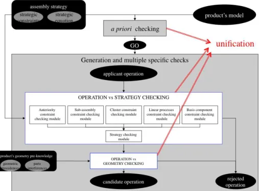
4.1. Main step improvements description
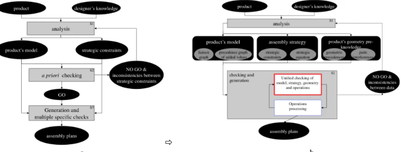
Figure 7.a. describes the proposed method as detailed in [Perrard 12]. Its main steps are:
- analysis (S1), in order to translate user’s knowledge into an assembly strategy and product data into a product model for ASP.
- a priori checking (S2), that makes it possible to verify the reality of the assembly strategy regarding the product model (checking of inconsistencies)
We propose to improve this method (Figure 7.b.) by:
- adding data concerning product geometry (component precedences and interferences), in order to automate the ASP as much as possible. To this end, we propose to adapt these data into precedences in order to use the proposed checking tool
- merging the a priori checking with the ASP. Indeed, the existing checking method can be easily extended to check operations that are generated during the ASP process. This will highly simplify the ASP, by avoiding many specific modules. To this end, an operation will have to be translated into an added values precedence set, in order to be processed by the checking module.
"
-a- -b-
Figure 7: main description of assembly plan generation process and proposed improvement
4.2. Adaptation of product geometry pre-knowledge
Fortunately, components precedence graphs are simplified added value precedence graphs. Indeed, in components precedence graphs, a node refers to a component. Actually, it refers to the linking of this component to a base component or to the components previously assembled on the base one. This base component is a source into such a graph.
Then, transformation of these graphs is easily done by replacing in each component’s node the name of the component by the set of liaisons to be realised between the component and the base and the previously assembled components.
Figure 8 describes an added values precedence graph for the electronic purse, when adding geometric knowledge to the product model. Geometric knowledge comes from previous precedence graph Figure 6.
Figure 8. Added value precedence graph for the electronic purse
In case of complex product structures, such a graph is not sufficient. However it is possible to use a Boolean equation to link the set of added values precedence [Henrioud 03]. For the simple case of Figure 8, the corresponding set of precedence is linked by a unique logic AND.
Then, the result can easily be integrated into our approach, because this Boolean equation of precedence can be processed by the a priori checking step as is.
In Section 3.8., we used interferences matrices to show an operative geometric constraint (OGC) related to the electronic purse. An OGC can be described by the couple of sub-assemblies:
Mating these two sub-assemblies, if possible, would perform {l3, l4}, to produce (({UC, LC, PCB},{l1, l3, l4},#,#). Then, we propose to describe this impossibility through anteriorities between added values in the following way:
"P’({l1},{l3, l4})
This indicates it is not possible to produce l3 or l4 if l1 is already performed. Then, it can also be written as follows:
) Q(l3, l1) + Q(l4, l1)
Today, interferences matrices generation can easily be automated through any CAD software [Lee 94] [Wilson 94].
Computing all reduced matrices issued from each liaison makes it possible to highlight simple operative geometric constraints (see example, in Section 3.8.). Then, it is possible to express these operative constraints in precedence constraints, as shown in previous Section 4.2.2. These precedence constraints can be added to the global formula to be checked. This process can be easily automated too. This proposition makes it possible to automatically fill a pre-knowledge database about product geometry.
However, this way of processing does not allow the generation of all operative geometric constraints, but only the simplest ones. Then, the process of assembly sequence generation is lighter for the user, due to the reduced number of questions (but not fully automated). This is due to the property of operative geometric constraints [Henrioud 89]:
OGC(SA1, SA2) ) OGC(SA1 ! SA1’ , SA2 ! SA2’) (for instance, for the electronic purse:
OGC(({UC, LC},{l1},#,#),({PCB},#,#,#))
) OGC(({UC, LC, FK},{l1, l2},#,#),({PCB, Ba},{l7},#,#)).
Usually, from our own experience, this way of processing makes it possible to reduce the number of questions by 90%, without user’s intervention. Obviously, this depends on the product structure.
However, willing to automatically find every OGC from the interferences matrices would conduct to redevelop an algorithm as complex as an ASP algorithm. This makes no sense here.
[Henrioud 89] improved the computing of the operative feasibility of a candidate operation by using an operative constraints database. Each response can be stored in this database, and some responses can be made by deducing the result from previous answers (using the above formula). This is very helpful to reduce the number of questions that the designer is asked. In this work, this proposal is kept.
Adding geometric knowledge to assembly sequence generation greatly improves its efficiency. We showed here that it can also be integrated into the approach we first presented in [Perrard 12]. Then, product geometry pre-knowledge can be described by strong and weak precedences and can be added to other constraints that are described in the proposed checking tool (product model, assembly strategy,…).
However, due to the nature of the geometric pre-knowledge (only interferences between parts), this approach cannot provide a fully automated method. An expert’s experience is still required to answer complex questions. But all simple and time-consuming questions can be automatically solved, allowing the expert to concentrate on the others.
If a database (about operation feasibility) is used, it is possible to greatly reduce designers solicitations. Moreover, this database can be pre-filled with product geometry pre-knowledge.
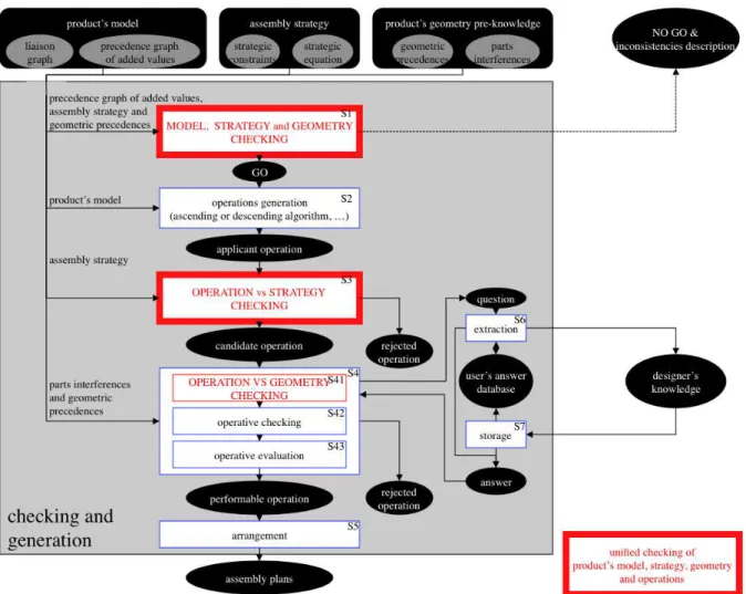
4.3. Merging of the a priori checking and ASP
Usually, ASP is mainly divided into five sub-steps (Figure 9): - operation generation (S2 in Figure 9)
- operation checking regarding the assembly strategy (S3 in Figure 9)
- operation checking regarding the product geometry and assembly system constraints (S4 in Figure 9). In this step, valid operations are evaluated too (S42 in Figure 9)
- arrangement of operations into assembly sequences (S5 in Figure 9)
The a priori checking module can be merged with ASP too (S1 in Figure 9). It will make it possible to greatly simplify step S3 (in Figure 9), and to pre-check sub-step S41 (in Figure 9).
Figure 9: Checking of the validity of an operation in the assembly sequence generation using the new unified
checking module
As explained in Section 1. and in Section 4.1., an operation has to be translated into an added values precedence set. An operation can be completely described by three elements:
- the composition of the two sub-assemblies SA1 and SA2 to mate, where SA1 = (Cp1,L1,S1,A1) and SA2 = (Cp2,L2,S2,A2)
- the added values VA12 that will be brought by the proposed assembly operation, where VA12 = (L12,S12,A12)
The result, a new sub-assembly SA3, can be deduced from the previous data, as follows: SA3 = SA1 ! SA2 ! VA12
Or more precisely:
SA3 = (Cp3,L3,S3,A3) where: Cp3 = Cp1 ! Cp2 L3 = L1 ! L2 ! L12 S3 = S1 ! S2 ! S12 A3 = A1 ! A2 ! A12 We note such an operation O by a 3-tuple:
O = (SA1 , SA2 , VA12)
Then, to be valid, the anteriorities induced by this operation, have to satisfy the extended strategic equation too. These induced anteriorities are produced by the four following groups:
1. P’(VA1, VA12) 2. P’(VA2, VA12)
3. Q’(VA1, VA2) $ Q’(VA2, VA1) = S’(VA1, VA2)
(to describe the parallelism that exists between the two sub-assemblies to mate)
These four groups of anteriorities make it possible to fully describe an assembly operation. However, we need to describe this last anteriority in greater detail. This can be made by considering SA3 as a sub-assembly. Then, we can write:
Let C be the set of components of Cp that are implied by the va3i added value of VA3 and let C’ be the
set of components of Cp that are implied by the va3’j added value of "VAVA3. For each couple
(va3i, va3’j) of VA ' VA, we can note that:
• if C , C’ = #, then there is no relationship between va3i and va3’j; then, they may be performed in
parallel into the acceptable processes. In the case of a linear process, then it’s va3i that has to be
performed before va3’j, in order to respect the sub-assembly VA3. This can be expressed by:
Q(va3i , va3’j)
• on the contrary, if C , C’ ! #, then it exists a temporal relationship between va3i and va3’j; they
have to be performed consecutively in the valid processes. The added value va3i has to be
performed first, in order to respect the sub-assembly VA3. This is expressed by: P(va3i , va3’j)
To conclude, any assembly operation can be described by a set of strong and weak anteriorities. Then, it is possible to check its validity using the proposed checking system. Then, any proposed operation can be compared with other constraints that are described into the proposed checking tool (product model, assembly strategy, product geometry pre-knowledge,…).
The previous adaptations such as
- translation of geometry pre-knowledge into precedence set, - description of an operation into precedence set,
make it possible to extend functionalities of the proposed a priori checking module. It is now possible to use it in order to check operations regarding the chosen assembly strategy, the product models,…
This is shown by improving the previous method (Figure 7a) into the new one (Figure 7b) by unifying the ‘a
priori checking’ and the ‘generation and multiple checks’ steps into the single ‘checking and generation’ step. Then, Figure 9 in Section 4.3.1. describes the main structure of assembly plan generation algorithms when using the new unified checking module. With this new unified module, the checking of any applicant operation in regard to any given strategy can be done.
Fortunately, the old dedicated set of operation verification modules can be advantageously replaced by the single
a priori checking module (Figure 10 below). These old specific modules were designed to check the feasibility of an applicant operation regarding a particular kind of strategic constraints. In the past, this had led to the design of one module for each strategic constraint.
4.4. Conclusion
In this paragraph, we proposed:
- to unify checking of model, geometry, constraints and operations (adaptations)
- to simplify the previous operation checking by avoiding the development of specific modules
- a universal tool, usable in any ASP method
The interest of this approach is obvious: it is no longer necessary to implement specific program modules, where each of them is dedicated to solving one particular kind of constraint regarding an operation. Here, simple Boolean equation solving is sufficient to check the consistency of the set of strategic constraints regarding the proposed operation.
It is now possible to integrate any user’s constraint, independently of product consideration.
In this section, the previous concepts of applicant operation checking that uses added value precedences are applied to some assembly operations of the electronic purse, in order to illustrate operations modelling and their checking using our approach.
5.1. First case
Let the applicant operation (Figure 11) be:
O1 = (({Ba}, #, #, #), ({Bc}, #, #, #), {l8})
Figure 11: Operation O1
It can be translated into the four groups of precedence constraints (see Section 4.3.2.): P’(#,{l8})
$ P’(#,{l8})
$ Q’(#,#) $ Q’(#,#)
$ [ P’({l8},{l5, l7}) $ Q’({l8},{l1, l2, l3, l4, l6, So, Sc, FC, La}) ]
The last term of this formula is exactly the opposite of the a) term of the proposed assembly strategy ST1 (see section 3.9.6.); then, the proposed applicant operation does not match the strategy. It is not a valid operation and will not be considered longer.
More practically, the assembly strategy described in Section 3.9.6. imposed the upper case (UC) as a base component. This first case does not satisfy this constraint.
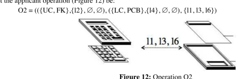
5.2. Second case
Let the applicant operation (Figure 12) be:
O2 = (({UC, FK},{l2}, #, #), ({LC, PCB},{l4}, #, #), {l1, l3, l6})
Figure 12: Operation O2
It can be translated into the four groups of precedence constraints (see Section 4.3.2.): O2 =
P’({l2},{l1,l3,l6}) term1
$ P’({l4},{l1,l3,l6}) term2
$ Q’({l2},{l4}) $ Q’({l4},{l2}) term3
$ P’({l1, l2, l3, l4, l6}, {l5, l7, So, FC, La }) $ Q’({l1, l2, l3,l4, l6}, {l8, Sc }) term4
Matching this expression with the strategy model gives: ST1 $ O2
= a) $ b) $ [c1) + c2) + c3)] $ term1 $ term2 $ term3 $ term4 = [c1) + c2) + c3)] $ a) $ b) $ term1 $ term2 $ term3 $ term4 = [ c1) $ …] + [ c2) $ …] + [ c3) $ …]
= [ P’({l1},"l1VA) $ …] + P’({l2},"l2VA)$ …] + [ P’({l3},"l3VA) $ …]
= P(l1, l2) $ P(l1, l3) $ P(l1, l4) $ P(l1, l6) $… c1) = P’({l1},"l1VA) $ P(l4, l1) $ P(l4, l3) $ P(l4, l6) term2 + P(l2, l1) $ P(l2, l3) $ P(l2, l4) $ P(l2, l6) $… c2) = P’({l2},"l2VA) $ Q(l2, l4) $ Q(l4, l2) term3 + P(l3, l1) $ P(l3, l2) $ P(l3, l4) $ P(l3, l6) $… c3) = P’({l3},"l3VA) $ P(l4, l1) $ P(l4, l3) $ P(l4, l6) term2 = FALSE
The proposed applicant operation does not match the strategy. It is not a valid operation and will not be considered any longer.
More practically, the assembly strategy described in Section 3.9.6. imposes linear processes. This second case does not satisfy this constraint.
5.3. Third case
Let the applicant operation (Figure 13) be:
O3 = (({UC, FK, LC},{l1, l2}, #, #), ({PCB}, #, #, #), {l3, l4, l6})
Figure 13: Operation O3
It can be translated into the four groups of precedence constraints (see Section 4.3.2.): O3 ) P’({l1, l2}, { l3, l4, l6})
$ P’(#, { l3, l4, l6})
$ Q’({l1, l2}, #) $ Q’(#, {l1, l2})
$ P’({l1, l2, l3, l4, l6}, {l5, l7, So, FC, La }) $ Q’(({l1, l2, l3, l4, l6},{l8, Sc})
Matching this expression with the strategy model, that is ST1 $ O3, and gives the following formula: ¬(P’({l8}, {l5, l7}) $ ¬P’({l1,l2,l3,l4,l6, So, Sc, FC, La}, {l8}))
$ [P’({l1},{l2, l3, l4, l5, l6, l7, l8} ! S ! A) + P’({l2},{l1, l3, l4, l5, l6, l7, l8} ! S ! A)] $ P’({l1, l2},{l3, l4, l6})
$ P’({l1, l2, l3, l4, l6}, {l5, l7,l8} ! S ! A)
which admits solutions. This means that O3 satisfies ST1. Hence, O3 belongs to the set of candidate operations. More practically, the assembly strategy described in Section 3.9.6. is respected in this third case.
However, when product geometry pre-knowledge constraints are added to the unified checking module, it gives (see Section 4.2.2.):
OGC(({UC, LC},{l1},#,#),({PCB},#,#,#)). "P’({l1},{l3, l4})
Then, it’s possible to deduce (see Section 4.2.2.):
OGC(({UC, LC, FK},{l1, l2},#,#),({PCB},#,#,#)).
Then, this impossibility is described in our method through anteriorities between added values by the following way:
However, this last term is the exact contrary of the first term that describes O3. Then, due to operative constraints, O3 will not belong to the set of performable operations. Using product geometry pre-knowledge, this operative geometric constraint can be found fully automatically.
Moreover, it is not necessary to extend the first OGC; indeed, it is sufficient as it is to discard O3.
In the reference paper, in order to illustrate the reduction of the search space, we shown for an industrial product inducing 416 processes without strategy, that the initial proposed strategy was inconsistent. Without running the assembly plan generation software, we were able to highlight the inconsistent terms of the initial strategy and to propose corrections. Then, four relevant assembly processes were generated only.
The new contribution of this paper concerns the exploitation of useful entry data (interference matrices, precedence graphs) in order to help automate assembly plan generation. These data along with operation models were unified into Boolean strong anteriorities in order to check their consistency with the assembly strategy. This new contribution greatly simplifies the software architecture, by merging many modules into a single one. This approach ensures the exploring of the whole acceptable search space when generating assembly plans. From the assembly planner’s viewpoint, it guarantees the generation of all relevant assembly plans according to design constraints and his/her assembly preferences. This advantage is not a feature of stochastic methods.
7
Assembly strategy and its proposed constraints constitute a convenient and useful framework to widely restraint research space when solving ASP problems. It makes it possible to quickly provide acceptable solutions, and only them, according to the designer’s description of what a good solution is made of. However, it is little used in the literature, mainly due to ignorance (few authors mention it), we presume.
However, since an assembly strategy describes the means to ease assembly operations, the product design choices have to be translated into assembly strategy. This can sometimes lead to inconsistencies into assembly strategy that has to be checked before running the ASP tool.
In the proposed paper, new contributions were proposed, such as:
- the description of any operation by a set of precedences. This makes it possible to check its relevance according to the chosen assembly strategy by using the same checking tool.
- the mere replacement of each dedicated checking module by a single one (Figure 10). This makes it possible to greatly simplify programming, and to guarantee a global checking of any applicant operation - the translation of traditional components precedence graphs into added value precedence graphs, in
order to match the input of the checking tool
- the translation of interference matrices into precedences, in order to integrate operative constraints pre-knowledge into ASP solving and reduce the research space, using product geometry.
Moreover, this paper proposes the use of two forms of knowledge:
- the assembly strategy and product geometry pre-knowledge description, that are described as precedence constraints in a first database,
- the assembly operative constraints, which are described in a second specific database.
These two databases allow the description of both product constraints and operative constraints, in order to match performable and acceptable assembly sequences. The description of product knowledge and operative knowledge into the same ASP tool, and the possibly to pre-fill corresponding databases before running ASP solving tool, should be performed by heterogeneous expert teams. Then, product designers, operative experts, process experts, logistics experts,… will share their needs through a common tool designed to ease discussion on ASP according to different points of view.
This work provides new research opportunities. The proposed approach can be useful to many different ASP solving methods (systematic such as ascending and descending, genetic, memetic,…). However, in order to measure the efficiency improvement, it would be interesting to adapt it to some ASP algorithms and to run trials in order to make comparisons.
The proposed approach can be easily applied to products with about 50 components. Research space can be easily contained by applying an easy-to-find assembly strategy. However, more complex products require more deliberation from the user, and some particular skills and know-how to define an adapted assembly strategy. Then, to solve such cases, it is first necessary to have a research to define what an assembly strategy has to be,
generally speaking. One answer would be to break the product down into hierarchized sub-assemblies and to run separately ASP system with each of them. Level number of this hierarchy may depend on product component number, function organization and relationship between components.
[Bai 05] Bai Y.W, Chen Z.N, Bin H.Z, Hun J (2005) An effective integration approach toward assembly sequence planning and evaluation. The International Journal of Advanced Manufacturing Technology, 27(1-2):96–105
[Bonneville 95] Bonneville F, Perrard C, Henrioud J-M (1995) A genetic algorithm to generate and evaluate assembly plans. Proc ETFA '95, INRIA/IEEE Symposium on Emerging Technologies and Factory Automation, Paris, France, 10-13 Oct, 2:231-239
[Chang 11] Chang L. ; Liu H. ; Gu T.L. ; Wei L. (Feb 2011) Product assembly sequence planning based on heuristic DCPM-FGA ; Computer Integrated Manufacturing Systems [Comp. Integ. Manufact. Syst.]. Vol. 17, no. 2, pp. 239-247.
[Choi 09] Choi Y-K, Lee D-M, Cho Y-B (2009) An approach to multi-criteria assembly sequence planning using genetic algorithms. The International Journal of Advanced Manufacturing Technology, 42(1-2):180–188
[Delchambre 92] Delchambre, A. (1992) Computer-aided assembly planning. Book ISBN 041243170X ; Chapman & Hall editors (London and New York)
[Demoly 11] Demoly F., Yan X.T.,Eynard B., Rivest L., Gomes S. (2011) An assembly oriented design Framework for product structure engineering and assembly sequence planning. Robotics and Computer-Integrated Manufacturing. Volume 27, Issue 1 :33-46
[Gao 10] Gao L, Qian W, Li X, Wang J (2010) Application of memetic algorithm in assembly sequence planning. The International Journal of Advanced Manufacturing Technology. 49(9-12):1175–1184 [Gottipolu 03] Gottipolu R, Ghosh K (2003) A simplified and efficient representation for evaluation and selection of
assembly sequences. Computers in Industry 50:251–264
[Gu 08] Gu T, Xu Z, Yang Z (2008) Symbolic OBDD representations for mechanical assembly sequences, Computer-Aided Design 40:411–421
[Henrioud 89] Henrioud J-M (1989) Contribution à la conceptualisation de l'assemblage automatisé: nouvelle approche en vue de la détermination des processus d'assemblage. Thèse d'Etat, University of Franche-Comte (France)
[Henrioud 91] Henrioud J-M, Bourjault A (1991) LEGA: a computer-aided generator for assembly plans. Chapter 8: In Homem De Mello L-S, Lee S (1991) Computer Aided Mechanical Assembly Planning. Series: The Springer International Series in Engineering and Computer Science. Vol. 148. Hardcover, 464 p., - ISBN: 978-0-7923-9205-7
[Henrioud 03] Henrioud J-M, Relange L, Perrard C (2003) Assembly sequences, assembly constraints, precedence graphs. Proc IEEE International Symposium on Assembly and Task Planning, 10-11 July, 90- 95 (ISBN: 0-7803-7770-2)
[Homem 91] Homem De Mello L-S, Lee S (1991) Computer Aided Mechanical Assembly Planning. Series: The Springer International Series in Engineering and Computer Science. Vol. 148. Hardcover, 464 p., - ISBN: 978-0-7923-9205-7
[Hsu 11] Hsu, Y.Y. ; Tai, P.H. ; Wang, M.W. ; Chen, W.C. (2011-07-01) A knowledge-based engineering system for assembly sequence planning ; The International Journal of Advanced Manufacturing Technology ; pp 763-782 ; vol. 55 ; issue 5 ; Doi: 10.1007/s00170-010-3093-5
[Hui 07] Hui W, Dong X, Guanghong D, Linxuan Z (2007) Assembly planning based on semantic modeling approach. Computers in Industry 58:227–239
[Jimenez 11] Jiménez, P. (2011) Survey on assembly sequencing: a combinatorial and geometrical perspective ; J Intell Manuf, DOI 10.1007/s10845-011-0578-5
[Lazzerini 00] Lazzerini B, Marcelloni F (2000) A genetic algorithm for generating optimal assembly plans. Artificial Intelligence in Engineering, 14(4):319-329
[Lee 94] Lee, S. (Mar 1994) Subassembly identification and evaluation for assembly planning ; IEEE Transactions on Systems, Man and Cybernetics ; Volume: 24; Issue: 3 ; pp 493 – 503
[Lit 01] De Lit, P.; Latinne, P.; Rekiek, B.; Delchambre, A. (2001) An ordering genetic algorithm for assembly planning ; International Journal of Production Research, 39(16): 3623–3640.
[Liu 11] Liu, Y.Y. ; Gang, Z. ; Bin Bin, W. ; Guang, R. Y. (August, 2011) Assembly Sequence Planning for Aircraft Component Based on Improved Clashes Matrix ; Journal on Applied Mechanics and
Materials (Volumes 88 - 89) ; VolumeComputer-Aided Design, Manufacturing, Modeling and Simulation ; pp 22-28
[Lv 10] Lv H-G, Lu C (2010) An assembly sequence planning approach with a discrete particle swarm optimization algorithm. The International Journal of Advanced Manufacturing Technology. 50(5-8):761–770
[Marian 03] Marian R, Luong L, Abhary K (2003) Assembly sequence planning and optimisation using genetic algorithms - Part I. Automatic generation of feasible assembly sequences. Applied Soft Computing 2/3F:223–253
[Martinez 09] Martinez M, Pham V-H, Favrel J (2009) Optimal assembly plan generation: a simplifying approach. Journal of Intelligent Manufacturing 20(1):15-27
[Mascle 01] Mascle, C. (2001) Disassembly-assembly sequencing using feature-based life-cycle model ; Proceedings of the IEEE International Symposium on Assembly and Task Planning ; pp 31-36 [Pan 10] Pan,H. ;Wen, W.H.; Li,T.M. (December 2010) Genetic Algorithm for Assembly Sequences Planning
Based on Heuristic Assembly Knowledge ; Journal on Applied Mechanics and Materials (Volumes 44 - 47) ; Volume Frontiers of Manufacturing and Design Science ; pp 3657-3661
[Perrard 07] Perrard C, Lutz P, Salgueiro P (2007) New bottom-up algorithm for assembly plan generation: opportunities for micro-factory design. Proc IEEE International Symposium on Assembly and Manufacturing, ISAM '07, 22-25 July, 276-281
[Perrard 12] Perrard, C. ; Bonjour, E. (2012) A priori checking inconsistencies among strategic constraints for assembly plan generation ; The International Journal of Advanced Manufacturing Technology ; pp 1-22 ; Doi: 10.1007/s00170-012-3942-5
[Rashid 12] Rashid M., Hutabarat W., Tiwari A. (2012), A review on assembly sequence planning and assembly line balancing optimisation using soft computing approaches. The International Journal of Advanced Manufacturing Technology, Published online 2 August 2011, Under press, DOI 10.1007/s00170-011-3499-8
[Shuang 08] Shuang, B.,S. ; Jiapin, C. ; Zhenbo, L. (2008) Microrobot based micro-assembly sequence planning with hybrid ant colony algorithm ; The International Journal of Advanced Manufacturing Technology ; Vol 38 ; Issue 11 ; pp 1227-1235
[Wang 05] Wang J.F, Liu J.H, Zhong Y.F (2005) A novel ant colony algorithm for assembly sequence planning. The International Journal of Advanced Manufacturing Technology, 25(11-12):1137–1143
[Wang 09] Wang L, Keshavarzmanesh S, Feng H-Y, Buchal R (2009) Assembly process planning and its future in collaborative manufacturing: a review. The International Journal of Advanced Manufacturing Technology 41(1-2):132–144
[Wang 10] Wang, Y. ; Liu, J.H. (2010) Chaotic particle swarm optimization for assembly sequence planning ; Robotics and Computer-Integrated Manufacturing, Volume 26, Issue 2, Pages 212-222
[Wilson 94] Wilson, H.W. ; Latombe, J.C. (December 1994) Geometric reasoning about mechanical assembly ; Artificial Intelligence, Volume 71, Issue 2, Pages 371-396
[Youhui 12] Youhui, L. ; Xinhua, L. ; Qi, L. (2012) Assembly Sequence Planning Based on Ant Colony Algorithm ; pp 397-404 ; vol 141; Book Title: Future Communication, Computing, Control and Management ; Springer Berlin Heidelberg ; Isbn: 978-3-642-27311-7
[Zeng 11] Zeng, C. ; Gu, T. ; Zhong, Y. ; Cai, G. (2011) A Multi-Agent Evolutionary algorithm for Connector-Based Assembly Sequence Planning ; Procedia Engineering, Volume 15, Pages 3689-3693
[Zhao 12] Zhao, S. ; Hong, J. ; Zhao, H. ; Li, S. ; Ding, L. (February 15, 2012) Research on assembly sequence planning method for large-scale assembly based on an integrated assembly model ; Proceedings of the Institution of Mechanical Engineers, Part B: Journal of Engineering Manufacture ; doi:10.1177/0954405411429248