HAL Id: hal-02547753
https://hal.archives-ouvertes.fr/hal-02547753
Submitted on 20 Apr 2020HAL is a multi-disciplinary open access archive for the deposit and dissemination of sci-entific research documents, whether they are pub-lished or not. The documents may come from teaching and research institutions in France or abroad, or from public or private research centers.
L’archive ouverte pluridisciplinaire HAL, est destinée au dépôt et à la diffusion de documents scientifiques de niveau recherche, publiés ou non, émanant des établissements d’enseignement et de recherche français ou étrangers, des laboratoires publics ou privés.
Quality Management Issues along Life-cycle of
Distributed Applications
Alioune Diagne, Pascal Estraillier, Fabrice Kordon
To cite this version:
Alioune Diagne, Pascal Estraillier, Fabrice Kordon. Quality Management Issues along Life-cycle of Distributed Applications. [Research Report] lip6.1998.025, LIP6. 1998. �hal-02547753�
Quality Management Issues along Life-cycle
of Distributed Applications
Alioune Diagne, Pascal Estraillier & Fabrice Kordon
Laboratoire d’Informatique de Paris 6 - Thème Systèmes Répartis et Coopératifs Université Pierre & Marie Curie
4 place Jussieu, 75252 Paris Cedex 05, France
E-mail: [email protected], [email protected], [email protected]
Résumé: Devant la complexité sans cesse croissante des applications informatiques et leur interconnexion à travers les réseaux, le paradigme de distribution devient un standard de fait. Une application informatique est souvent conçue de nos jours comme devant faire partie d'un système plus grand auquel il peut rendre des services ou en requérir de lui. L'approche par modules (ou composants) est une démarche de plus en plus fréquente en génie logiciel. Elle con-siste à principalement à construire des applications à partie de composants spécifiés, vérifiés et réalisés ad-hoc ou réutilisés. Vérifier et valider la conception de même que optimiser la solution réalisée deviennent alors des besoins le long du cycle de vie d’une application. Un autre besoin très important est d’assurer qu’il n’y a aucune dérive entre le résultat de la spécification et la solution réalisée. Nous proposons une approche multi-formalismes avec deux modèles de com-posants. Le premier est dédié à la spécification et permet d’entreprendre des activités de vérifica-tion et de validavérifica-tion. Le second est dédié à la réalisavérifica-tion et offre des moyens pour optimiser le code généré. Les deux partagent le même fondement formel qui sont les réseaux de Petri colorés et la traçabilité entre eux est assurée de manière semi-automatique sur la base de règles formel-les.
Mot-clefs : Applications réparties, Qualité, Traçabilité
Abstract : Face to the much and much complexity in computer applications and their intercon-nection via networks, the distribution paradigm has become a standard. Nowadays, an applica-tion is often built to be part of a larger system to which they can offer services or require them from it. The component-based approach is becoming standard in Software Engineering. It is mainly an incremental way to build applications from components that have been tailored, vali-dated, verified and implemented ad-hoc or reused. Verification and validation during conception as well as optimization during implementation become therefore important activities in applica-tions life-cycle. Another strong need is to ensure that there is no drift between what is specified and the implemented solution. We propose a multi-formalisms approach with two component models. The first one is dedicated to specification and allows to undertake verification and vali-dation. The second one is dedicated to code generation and offers optimization means. Both, they have colored Petri nets as formal basis and the traceability between them is semi-automatic, based on formal rules which ensure lack of drift from specification to implementation.
Keywords : Distributed Applications, Quality, Traceability
1
Introduction
Face to the much and much complexity in computer applications and their interconnection via networks, the distribution paradigm has become a standard. The immediate consequence of dis-tribution is the necessity to consider the logical partitioning of an application into logical interac-ting entities (the components). The logical partitioning allows to define what is required from the components and how this is achieved as well as their composition to achieve the overall functio-nalities of the application. At this level, one needs to ensure that the partitioning match the initial requirements in a satisfactory (i.e. at least safe and reliable) way. The logical partitioning leads from specification downto implementation of the application under consideration. The
implemen-tation of the application needs to be tailored according to a given infrastructure that will support the operation of the application. The infrastructure is made of physical entities, often distributed over a network. Tailoring the implementation according to this infrastructure allows to optimize the performance, to improve the availability of the functionalities and the resource sharing by choosing the most appropriate location of software pieces on physical machines.
At the specification of a software, we have strong verification and validation needs. System ar-chitects and application designers need to prove their models formally. With techniques like mo-del-checking, they can exhaustively simulate the operating state of their applications and verify temporal dependencies between the states reached or the actions performed. Some basic proper-ties like deadlock-freeness can be checked. Domain dependent properproper-ties can also be investigated. The conceptual model of component we propose for this stage allows to achieve the logical par-titioning while managing these aspects. Quality issues at specification level are mainly domain dependent properties to prove. They should be traced downto implementation. The model allows to focus on what the components do (i.e. to model into details the architecture of an application) as well as on how they achieve this (i.e. to model their internal aspects). Properties expected from the application can be stated and verified. For that purpose, the model is transformed into a colo-red Petri net representation that allows simulation and model-checking. Simulation makes the spe-cification executable and hence use cases of the target application can be validated early at specification stage.
Once the model built at specification reaches a satisfactory level, the next step is to implement it in an optimized way. The main quality issue at this level is to ensure the that no divergence is introduced between the model and its implementation. To do so, the transformation from concep-tual model to operational model is formally defined [4]. Transformation of the operational des-cription into Petri nets is dedicated to program optimizations; it takes into account the target infrastructure to sketch and evaluate locations strategies.
To avoid useless work and moreover to trace quality along the life cycle, there is established a formal correspondence between the component models. This correspondence allows, by giving some necessary precisions on the conceptual model, to derive an operational one. Nevertheless, the coupling between the two component models is loose and each and its associated toolset can be used separately.
The paper is organized as follows: the section 2 presents the overall approach integrating our components as well as their formal basis. The section 3 is dedicated to the conception of distribu-ted applications while the section 4 deals with their implementation and deployment. Conclusions and future works will come in section 5.
2
Overall Approach
As for the Proteus approach [6], we distinguish two sets of activities : the specification and im-plementation of an application.
A designer first deals with conceptual aspects of the application like the functions it has to pro-vide or the interoperability of its software components. Once the conceptual description has rea-ched a satisfactory maturity, he may then think about operational or implementation related details.
These two separate aspects of the design deal with different types of information. So we express them by means of separate representations. However, the second one is deduced from the first one and a simple procedure can be provided.
Both steps should also consider the properties of the application. Properties may be derived: • from the requirements, like «the application has only one terminal state»;
• from conception hypothesis, like «this service must be run first to operate a subsystem»; • from operational hypothesis, like «this variable can be duplicated in order to increase
Verification or computation of such properties cannot be done without having a formal descrip-tion of the applicadescrip-tion. Petri nets are suitable for such a role but they are not uneasy to handle large specifications. Moreover their capabilities allow one to describe both conceptual and operational specifications. It is then easy to mix up both features in the same model.
2.1
The MARS Methodology
The MARS methodology relies on both Petri nets and use high level description techniques (Figure 1). Well formed Petri Nets [1] fit all the formal needs. It supports the computation of pro-perties in the model. On top of Petri nets, we propose two High level formalisms :
• OF-Class (Object Formalism Class) [2] provides a conceptual description of the application. It provides information about the association of components, the way they behave and how they should be used. It may be simulated and transformed into the formal description;
• H-COSTAM (Hierarchical COmmunicating STAte Machine Model) [8] allows the designer to deal with operational aspects of his/her application. Such a description may be derived from the conceptual description by addition of information. It can also be transformed into the for-mal description and enable code generation.
These formalisms correspond to a sort of Petri net encapsulation. They offer more sophisticated predefined constructions are strongly related to Petri net concepts in order to maintain traceability.
Figure 1 : Formalisms and Operations in our Methodology.
Four operations between these three representations are characterized:
• Two types of transformations from respectively OF-Class and H-COSTAM into Petri nets enable the link with the formal representation. These transformations are different while they do preserve different properties. The result is a Petri net that express either functional relations (to get conceptual properties of the application) or an operational description (to extract opera-tional properties that should lead to the optimization of the prototype);
• Code generation is performed from the operational description. It may compute and use ope-rational properties to optimize code generation. In the context of distributed applications, this operation must produce both a compilable program and a location proposal. This location pro-posal is computed for a given hardware architecture description [4].
• Elicitation of the application is the transformation of a conceptual description into an opera-tional one. it occurs when the Conceptual description appears to be safe and progressively introduces operational information (how communication is performed, where strictly sequen-tial parts of the application are, etc.) that leads to the production of an equivalent H-COSTAM specification that is more likely oriented towards code generation of distributed applications. It should not be automatic like the two other ones and can be considered as a list of questions that gradually clarify all the points of the implementation Information about this operation can be found in [3]. Conceptual description (OF-Class) Operational description (H-COSTAM) Executable prototype Formal description (Petri nets) From OO Outcome
2.2
Objectives and Common Features of the High-level Formalisms
In both OF-Class and H-COSTAM, a specification should be divided in two parts:
• The model of the execution environment: it corresponds to already existing pieces of software for which no modification or evolution is possible. The operating system of a compu-ter is a good example of execution environment;
• The model of the application itself that is divided in two separate parts: parts that are reused from others applications (they already exist but can be modified if necessary) and specifically designed components.
Both conceptual and operational descriptions are hierarchically structured. They are divided in pages. Two granularities are considered:
• the macro-level contains information that are more likely dedicated to the definition of rela-tions between either elementary units or sub-systems,
• the micro-level that describes the behavior of an elementary entity.
In both cases the corresponding Petri nets are flat. The hierarchy of the input description brings the structuration of the Petri net model. Such a structuration facilitates both the understanding and the verification of the model properties.
3
Specification and Verification
For specification activities, we use a dedicated component model named OF-Class. We present it hereafter with its verification and validation facilities. OF-Class is not relevant for software en-gineering activities like requirement enen-gineering. We assume that such activities have been alrea-dy run and an outcome which has an object-based structure has been produced (see Figure 1).
3.1
The Conceptual Formalism : OF-Class
OF-Class is a template dedicated to the conceptual description of distributed applications. In one hand, it takes into account the main features of such applications pointed out in the computa-tional viewpoint of the Reference Model of Open Distributed Processing (RM-ODP) [12]. It pro-vides a constrained interfacing mechanism in order to achieve most formal interactions. In another hand, it is formally associated with a modular Colored Petri Net (CPN) model [2]. This modular CPN models the internal automaton describing the behavior of an OF-Class. It allows to undertake verification of both the structure and the dynamic of specifications.
OF-Class does not claim to support object-oriented activities such as analysis and design. However, it is as generic as possible to enable transformation from any OO model to undertake its verification.
3.1.1 Modeling Distributed Applications with OF-Class
Specification and design of a distributed application consists of describing the components and their interactions. To evaluate the designed application, the expected properties of its components and their interaction must be expressed.
The execution environment of the application is considered to be a set of valid components ac-cessed across bounded interfaces. The environment of a given component is made of both the exe-cution environment of the whole application and the set of other components it is interacting with.
Properties that are expected from a distributed application are of two kinds:
• local properties on components concerning the managed resources or the offered services. These properties can be expressed as invariants - like in RM-ODP - on those resources or availability constraints on services. These properties are expressed on the micro-level descrip-tion in an LTL temporal logic,
com-ponents (like deadlock and starvation free application), meaningful reachable states (home state and reversibility). They can be expressed as LTL assertions on the application evolution.
The model of the application may include observation facilities. They are information supplied to run the application and evaluate its behavior. They model the information necessary to simulate execution of the application. The simulation is centralized. However, building incremental sub-systems with an abstracted environment allows to avoid the construction of the whole system. One can stress on a given part of the system considered as a glass box while other parts are abstracted as black boxes.
A component has private resources to manage (it is the only one to manipulate them), offers to the environment services that handle those resources and an abstraction on its environment. To achieve these goals, there are two description levels.
3.1.2 The Micro-Level in OF-Class
The micro-level describes the local resources of a component and their possible transforma-tions. A resource is an entity local to a component that can be accessed only through invocations of services offered by that component. Transformations of resources are done by means of ele-mentary actions. These actions are grouped as sets called operations.
An operation is a set of actions performing a given semantic transformation on local resources. An operation can issue requests to the environment. It has input and output parameters, local va-riables and a return code. Two special operations handle the dynamic creation (constructor) and deletion (destructor) of instances.
A component may also trigger some sets of actions when reaching some meaningful states or when some events occur while interworking with the environment. These mechanisms are slightly different from operations because they cannot be invoked by consumers. Such actions are called
triggers and have no equivalence in RM-ODP concepts. Triggers bear eventually preconditions, i.e. predicates on the resources values or input parameters specifying the state in which they are executed. Triggers can undertake interactions with the environment.
3.1.3 The Macro-Level in OF-Class
The macro-level describes the structural and dynamic links necessary for interaction of com-ponents in a distributed application. Structural links allow to compose discrete comcom-ponents in or-der to build a more complex one. Dynamic links are:
• the services offered by a component. An offered service is a set of operations with contractual constraints like precedence or access semantic (synchronous, rendez-vous, etc.). It is a cohe-rent partial view on the behavior provided to the environment for access to the local resources, • the services required from the environment show a given component the way it must behave
towards it. They are provided by other components of the application.
3.2
Verification and Validation with OF-Class
OF-Class is formally mapped to a modular colored Petri net model, the OF-CPN model [2]. The transformation is based on the principles developed in [8]. The transformation produces one mo-dular net per OF-Class with markings traducing the instanciation process. Once the transforma-tion achieved, we can give for each module an abstractransforma-tion of its environment and run the construction of the reachability graph. The abstraction is a black box that just issues requests and responses to the component while respecting the contractual constraints (see Section 3.1.3). This reachability graph support the model-checking of the local properties.
To verify the global properties, we reduce the reachability graphs of the components to the ob-servable actions (consuming request tokens, producing result tokens, etc.) and we compute a syn-chronization of the reduced labelled transition systems [3]. The reduction is based on an
observation equivalence on states. The observation equivalence is computed on isolated nents before composition. Thus, we limit the combinatorial explosion that comes up with compo-sition.
By simulating the generated Petri nets, we make the specification model executable. This al-lows to early validate scenarios at the specification stage.
4
Implementation and Deployment
In MARS, implementation and deployment are performed using the operational formalism : H-COSTAM. We first present it before exploring issues of program generation and its deployment over a set of processors.
4.1
The Operational Formalism: H-COSTAM
This section does not aim to give a full definition of H-COSTAM that can be found in [8]. We just remind here the main principles of H-COSTAM and introduce new capabilities.
H-COSTAM is a formalism dedicated to the operational description of distributed applications. Its features are the following:
• Hierarchy enables to get a readable and structured specifications. Translation into Petri nets then preserves a «good» structure that should facilitate the computation of properties;
• Strongly typed communication mechanisms define a communication model in the sense of CSP [10]. However, communicating entities are sequential state machines or subsystems ins-tead of instructions;
• genericity (in the sense of the Ada language) eases the parameterization and the reuse of com-ponents.
4.1.1 Structure of an H-COSTAM Specification
An H-COSTAM specification is composed of pages that belong either to the macro-level or the micro-level (see Section 2.2.). A macro-level page describes the relation between entities that are either subsystems (and then a link to another macro-level page) or a process (and then a link to a micro-level page).
Pages are tagged external if they describe the functional behavior of the execution environ-ment. They are tagged internal if they correspond to the description of the application itself. If a macro page is tagged external, all its components should be tagged external as well.
External and internal components cannot be interpreted the same way:
• external components represent pieces of software the application will be linked to. The only necessary information is an H-COSTAM translation of the usage-manual introduced for OF-Class (see Section 3.1.3),
• internal components are parts of the application and must be described in detail. The code generator will use this information to produce programs that will be linked to the already exis-ting code associated to the external components.
4.1.2 The Micro-Level in H-COSTAM
The micro-level describes a class of sequential state machine (called process in H-COSTAM). A process is interfaced with the outside world by means of media that define an interaction. Each medium is strongly typed by both the type of data that goes through and its behavior. There are three classes of media:
• a multi rendez-vous corresponds to a synchronization between a set of N entities. The syn-chronization corresponds to a Petri net transition shared by several processes, can be guarded by a condition and allows the exchange of information between the participants;
• a link corresponds to asynchronous transmissions that have some specific behavior. Three behaviors are defined: FIFO (the order of messages remains), LIFO (last message in is first out) or random (no order preserved). Links may be connected to an arbitrary number of enti-ties. Each input entity may send a message that will be received by all the output entienti-ties. • a RPC relates a class of clients to a class of servers and corresponds to a remote procedure
call. On the client side, it appears like an atomic operation (equivalent to a synchronization). On server side, it behaves like two FIFO links, the first is an input that corresponds to the ser-vice invocation, the second is an output and represents the end of the serser-vice;
• a factory represents an entry point for special messages asking for the creation of processes. Media that interface a process are connected to an internal automaton that is expressed using a State/Transition model whose semantic is close to the one of Well Formed Petri Net. The internal automaton has to be a sequential state machine in the sense of [7].
The automaton describes the static behavior of the elementary process. Each of them may be instanciated statically (a set of instances are predefined at the initialization of the application) or-dynamically (when a special event comes from a constructor).
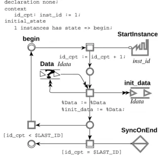
Figure 2 : Example of a micro-level description.
Each instance may have its own distinct context represented by a set of private variables. A res-tricted set of operations is available on these variables: Identity, successor, predecessor, product and restriction. Such a limited set is necessary because we want to maintain an equivalence with Petri nets. However, if more complex and specialized capabilities are needed, they can be intro-duced by means of external components.
Communication media may also be local to the entity. They are then potentially shared by all instances and cannot be accessed from outside.
Figure 2 describes a elementary state machine class that has three interfaces media (bold gray). StartInstance is a factory for creation messages. init_data is a communication link for sending data to another unit and SyncOnEnd represents a synchronization with another set of components. Random link Data appear here as a data storage zone (for readability, the initial content is not pro-vided).
each instance of this elementary state machine creates N tasks (according to the value of cons-tant $LAST_ID imported from the upper level presented in Figure 3), send them information and
then synchronize on their end.
According to the declaration part, there is only one statically created instance of this state ma-Data Idata [id_cpt < $LAST_ID] [id_cpt = $LAST_ID] %Data := %Data %init_data := %Data; SyncOnEnd init_data Idata StartInstance inst_id id_cpt := id_cpt + 1; begin declaration none; context id_cpt: inst_id := 1; initial_state
chine (it begins at state begin).
4.1.3 The Macro-Level in H-COSTAM
The macro-level describes the relations between entities. So, involved objects in a macro-level page are either communication media (including constructors) or entities.
A communication mediumis either the real one associated to entities interfaces or an interface with an upper level. Like in the micro-level, only interfaces media may be accessed out of the pa-ge. In the macro-level, constructors (local or interface with the upper level) cannot be defined if they are not connected to the interface of at least one contained unit.
An entity is either a process, defined in a micro-level page, or a subsystem, described in another macro-level page. In both case, media that define interfaces of contained entities are then associa-ted to the real ones that perform the communications.
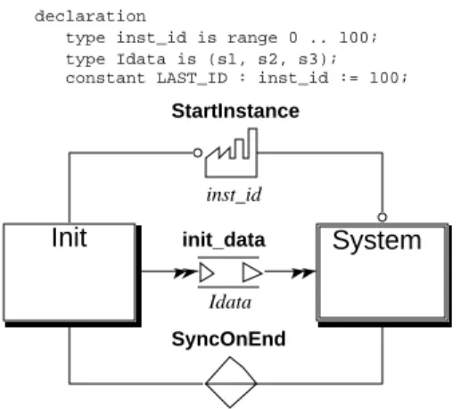
Figure 3 : Example of a macro-level description.
Figure 3 shows the macro level page that contains two subcomponents : init, the
state-machi-ne defistate-machi-ned in Figure 2 and System, a subsystem containing several sequential processes. So,
ac-cording to this page, Init creates 100 instances of System class, provide them with information and
synchronize to stop when all are terminated.
4.1.4 Using Petri Nets for Process Partitioning in an H-COSTAM Model
The H-COSTAM specification of the application corresponds to the view of the designer. Such a view is quite easy to automatically interpret in order to generate programs while it contains all the relevant information. However, it might not be the most accurate one : some tasks may be grouped differently and lead to a better partitioning of the application.
A translation of the H-COSTAM specification into a flat and structured Petri net enables to run the partitioning algorithm presented in [9] which automatically extracts sets of concurrent state machines from a Petri net model. Its main problem of is that it can fails when applied to unstruc-tured Petri net models. However, this cannot be the case while the transformation from H-COS-TAM toPetri nets is controlled and performed a way that avoids such cases. So, the algorithm finds at least one process partitioning (the one of the designer). Other ones (if there are any) cor-respond to other potential partitioning of the application.
Such a procedure enables the computation of alternatives task decomposition of an application. The appropriate one may then be selected considering characteristics of the target architecture (number of processors) or implementation choices (minimization of synchronous communica-tions for example).
4.2
Code Generation from an H-COSTAM Model
Program produced from an H-COSTAM specification are build after the generic architecture
Init System
declaration
type inst_id is range 0 .. 100; type Idata is (s1, s2, s3); constant LAST_ID : inst_id := 100;
SyncOnEnd init_data
Idata
StartInstance
presented in Figure 4.
Most of it are generic components that are customized after characteristics of the input model : • The type manager handles all types manipulation and operations;
• The media manager, implemented as sets of concurrent processes, take care of synchronous (multi-rendez-vous, RPC) and asynchronous (links) communication;
• The prototype manager is in charge of initialization and termination of the prototype execu-tion. It also takes care of dynamic process creation (factories). There is one prototype manager per target CPU.
Figure 4 : Generic architecture of a program derived from H-COSTAM specification.
All communications are supported by a communication kernel that handles local communica-tions as well as distant one :
• Local communication may be supported by the compiler runtime in languages that supports multitasking (typically Ada95). Otherwise, Operating System primitives are used to imple-ment this function;
• Distant communication may be supported by message passing interfaces like PVM [5] or MPI
[10].
H-COSTAM genericity can be supported using the corresponding feature in the target language (templates in C++, genericity in Ada95, etc.). Otherwise, a rewriting mechanism similar to macros has to be implemented in the code generator.
Tasks classes issue from H-COSTAM processes corresponding to the application (i.e. tagged internal) are the main customized elements of produced programs. Other specification compo-nents represent the execution environment and are «glued» with the prototype during code gene-ration. It is not really a linking procedure while the implementation of such components must respect convention regarding interfaces (connection between H-COSTAM processes are done using communication media only).
4.3
Program Deployment based on the Prototype Structure
Code generation and application deployment are separately computed in the MARS methodo-logy. Each task of the prototype derived from the generic architecture presented in the previous section is has to be associated to processors. When the prototype is produced and its final archi-tecture completely defined, it is of interest to find out in the archiarchi-tecture typical configuration for which a «good» processor allocation can be performed.
Usually, having chosen a partitioning for a given specification (see Section 4.1.4.), the designer may have some feeling about «nice» configurations that facilitate task allocation over a set of pro-cessors. It is of interest to use Petri nets in order to evaluate such expectations. We will present in this paper to an example : pipe-line detection.
Our technique is divided in two phases : 1) the designer states his feelings, 2) a Petri net is syn-thesized and evaluated in order to check (or invalidate) the hypothesis.
Process
Generic unit (contains dedicated data) Dedicated unit links manager multi-rdv and RPC type manager Prototype manager Media Manager Communication Kernel libraries binding
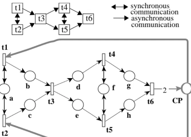
Figure 5 : Task configuration and the associated Petri net to verify the existence of a pipe-line. Pipe-lines are easy configuration for task allocation over a set of processors. Each step of the pipe-line is usually affected on a processor in order to increase parallelism.
To evaluate if a pipe-line hypothesis is correct, we produce a Petri net model using the fol-lowing rules :
• Each task of the prototype is represented by a transition,
• Communication between tasks is modeled by means of places. Connection between places is bidirectional if it is a synchronous communication (issued from a RPC or a multi-rendez-vous), unidirectional otherwise;
• A complementary place «closes» the pipe-line. If it exists it should generate an place inva-riant.
The pipe-line existence is confirmed if there are invariants that cover the pipe-line.
Figure 5 illustrates how our technique works. The task arrangement on top of the Figure is translated into a Petri net model according to the rules already presented. Place CP «closes» the net and introduces two invariants (2g + b + c + dc + CP = cst and 2d + b + c + 2e + CP = cst) that verify the pipe-line existence. These invariants are generated by the CP place and its complex structure (due to synchronizations betwen couples t1/t2 and t4/t5) explains the presence of two invariants.
5
Conclusion and Future Work
This paper presents a methodological support to enable the management of quality and its tra-ceability along the life-cycle of distributed applications. At the specification level, properties ex-pected from the application can be stated and verified on the model built. By the elicitation operation, we ensure that the operational representation does not diverge from the conceptual one. The code generated from this operational model is optimized by computing structural invariants implicit in the model. Deployment of the generated code on specific hardware architectures can be sketched in order to evaluate it.
Currently we are working on tests selection techniques to confirm the quality and its traceabi-lity. We aim by test generation and selection to exhibit on the implementation the mechanisms that ensure the properties proved at the specification stage.
6
References
[1] G. Chiola, C. Dutheillet, G. Franceschini & S. Haddad, "On Well-Formed Coloured Nets and their Symbolic Reachability Graph", High Level Petri Nets. Theory and Application. Edited by K. Jensen G.Rozenberg, Springer Verlag 1991
t1 t2 t3 t5 t6 t4 synchronous asynchronous communication communication CP e d c b h g f a t5 t6 t4 t3 t2 t1 2
[2] A. Diagne & P. Estraillier, "Formal Specification and Design of Distributed Systems", Proc. Int’l. Workshop FMOODS’96, Paris, Mars 1996.
[3] A. Diagne & P. Estraillier, "A Component-based Framework for the Specification, Verification and Validation of Open Distributed Systems", Technical Report, LIP6 # 1997/037.
[4] A.Diagne & F. Kordon, "A Multi Formalisms Prototyping Approach from Formal Description to Implementation of Distributed Systems", in proceedings of the 7th Int’l Workshop on Rapid System Prototyping, N.Kanopoulos Ed, pp 102-107, IEEE comp Soc Press, Greece, June 1996
[5] W. El Kaim & F.Kordon, "An Integrated Framework for Rapid System Prototyping And Automatic Code Distribution", in Proc. of the 5th IEEE Int’l Workshop on Rapid System Prototyping, Grenoble, France, IEEE Comp Soc Press N° 94TH0633-8, pp 52-61, June 1994
[6] A.Geist, A.Beguelin, J.Dongarra, W.Jiang, R.Manchek & V.Sunderam, "PVM: Parralel Virtual Machine, A Users’ Guide and Tutorial for Networked Parrallel Computing", MIT Press, 1994
[7] A. Goldberg, J. Prins, J. Reif, R. Faith, Z. Li, P. Mills,L. Nyland, D. Palmer, J. Riely & S. Westfold, "The Proteus System for the Development of Parallel Applications", in Prototyping Languages and Prototyping Technology, M. Harrison, ed., Springer-Verlag, 1996
[8] M. Hack, "Extended State-Machine Allocatable Nets (ESMA), an Extension of Free Choice Petri Net Results", MIT, project MAC, Computation Structures Group, Memo 78-1, 1974
[9] M. Heiner, "Petri Net Based Software Validation, Prospects and Limitations." Tech. Rep. TR92-022, GMD/First at Berlin Technical University, Germany, March 1992.
[10] C.A.R. Hoare, "Communicating Sequential Processes", Printice-hall International editor in computer
science, C.A.Hoare series editor, 1985
[11] F. Kordon & W.El Kaim, "H-COSTAM: a Hierarchical Communicating State-machine Model for
Generic Prototyping", Proc. of the 6th "Int’l Workshop on Rapid System Prototyping", N.Kanopou-los Ed, IEEE comp Soc Press 95CS8078, pp 131-138, Triangle Park Institute, June 1995.
[12] F. Kordon & J.F. Peyre, "Process decomposition for Rapid Prototyping of Parallel systems", 6th Int’l
Symposium on Computer and Information Science, Kener, Antalya, Turkie, October 1991
[13] MPI Forum, "MPI: A message-passing interface standard. International", in Journal of
Supercompu-ter Application, 8 (3/4), pp165-416, 1994
[14] "The Reference Model of Open Distributed Programming, Overview, and Guide to Use" Draft