HAL Id: hal-00739847
https://hal.archives-ouvertes.fr/hal-00739847
Submitted on 9 Oct 2012
HAL is a multi-disciplinary open access
archive for the deposit and dissemination of
sci-entific research documents, whether they are
pub-lished or not. The documents may come from
teaching and research institutions in France or
abroad, or from public or private research centers.
L’archive ouverte pluridisciplinaire HAL, est
destinée au dépôt et à la diffusion de documents
scientifiques de niveau recherche, publiés ou non,
émanant des établissements d’enseignement et de
recherche français ou étrangers, des laboratoires
publics ou privés.
DiplodocusDF, a domain-specific modelling language for
software defined radio applications
Mercury Jair Gonzalez Pina, Rabéa Ameur-Boulifa, Renaud Pacalet
To cite this version:
Mercury Jair Gonzalez Pina, Rabéa Ameur-Boulifa, Renaud Pacalet. DiplodocusDF, a domain-specific
modelling language for software defined radio applications. (SEAA’12), Sep 2012, Cesme, Izmir,
Turkey. pp.509-514. �hal-00739847�
DiplodocusDF, a domain-specific modelling language
for software defined radio applications
Jair Gonzalez-Pina, Rab´ea Ameur-Boulifa, Renaud Pacalet
Telecom ParisTech, LTCI CNRS2229 Route des Cretes, B.P. 193, 06904 Sophia-Antipolis Cedex, France Email: [email protected]
Abstract—Given its intrinsic complexity, it is not efficient to develop software defined radio (SDR) systems following traditional methodologies. A new methodology is necessary, which should allow the description of the applications at higher abstraction levels. This paper describes such a methodology. It includes domain-specific modelling languages (DSML) for SDR applications / SDR architectures, and the mechanisms to generate automatically the deployment code. The DSML language is described with precise syntax and semantics to support simulation, synthesis, and formal analysis. The potential of the modelling language is illustrated by designing a cognitive radio application called Welch periodogram detector.
I. INTRODUCTION
Modern radio systems are required to support multiple com-munications standards. Software defined radio (SDR) archi-tectures enables this functionality by providing reconfigurable processing architectures. The SDR architectures are controlled by embedded software applications called SDR applications (or waveforms).
We propose a model-driven design (MDD) methodology for SDR applications. For this, we identified and analysed the characteristics of SDR applications and SDR architectures and defined DiplodocusDF, a domain-specific modelling language (DSML) that captures the semantics of waveforms/architectures in a high level of abstraction. DiplodocusDF allows fast simula-tion for design explorasimula-tion and automatic code generasimula-tion from the abstract model.
This paper presents a precise description of the syntax and semantics of DiplodocusDF. This language is based on the following principles: (a) separation of application and archi-tecture models (b) data-flow/declarative oriented modelling, such that the applications are modelled as a set of data-dependent tasks, without requiring a control-flow description, (c) data-model refinement, to capture with more detail the semantics of waveforms, (d) the use of UML, as it allows independent description of applications and architectures. Also, UML has the flexibility to be extended to cover data-flow models and SDR-like data channels. Moreover, it is already well accepted as modelling language and is supported for modelling capture and simulation by several tools, such as TTool [1].
The research leading to these results has received funding from the European Community’s Seventh Framework Programme (FP7/2007-2013) under grant agreement SACRA n 249060.
II. SDRSYSTEMS
SDR systems present high-performance requirements (hard deadlines, low-power consumption, etc.), and they are required to be executed in highly constrained resource environments (size, power, etc.). Considerable research has been conducted to propose sophisticated SDR architectures, which achieve high computation efficiency and reconfigurability. For example, the architecture in [2] offers an asynchronous hardware network of coarse grained operators which are configured by a main proces-sor, and where the data is sent directly among operators, without requiring DMA transfers. The architecture in [3] offers a group of co-processors were each coprocessor is capable of executing several similar operations (sequentially), e.g. component-wise product and component-wise addition. This architecture relies on DMA to move data between the coprocessors. The architecture in [4] provides a set of software functions which are all executed by a general purpose processor.
The challenge is now (as highlighted in [5], [6]) the develop-ment of waveforms . Waveform developdevelop-ment requires knowledge of communications algorithms and communications standards, but it involves also many other aspects more related to its implementation, such as: embedded software languages, real-time, fault tolerant, reconfigurability, security, operating sys-tems, multi-threading, security, sophisticated SDR platforms, etc. Besides, the waveform developer should resolve problems of portability, interoperability, and performance.
It is not efficient to develop such systems following the traditional methodology. It requires many design implementation and verification cycles, trying to reconcile, resolve and unify potentially opposite aspects. It is necessary to abstract the waveform description from all the implementations complexity, and automate the transformation into deployment description.
We extended DIPLODOCUS [7], a MDD methodology for for-mal design exploration, to DiplodocusDF, a MDD methodology for the domain of SDR: (1) to support the description of wave-forms, which are based on data-flow, while DIPLODOCUS was only suitable for control-based applications. (2) to support the particularities of novel SDR architectures. (3) to support transla-tion into C-language descriptransla-tion. The DiplodocusDF models can be simulated, formally verified and automatically transformed into the final C-language representation.
This paper focuses on the precise specification of DiplodocusDF. It is a key component of the overall methodology.
It effectively separates the pure waveform aspects from the implementation details. The syntax and semantics of DiplodocusDF were defined formally. Given that DiplodocusDF models have precise semantics, they support translation into formal languages, rapid simulation and automatic code generation.
III. MODELLINGSDRSYSTEMS
SDR systems are logically divided into two main layers: SDR architectures and waveforms, as shown in Fig.1. SDR architectures are based on coarse grain parametrizable operators (POs) which are common to most of the existing telecommuni-cations standards. POs are drawn as boxes where P1, P2, and Pn refer to their parameters. For example a fast-fourier transform (FFT) operator will require as parameter the number of points used in the FFT analysis. POs can be implemented either as SW functions, or as HW components (accelerators, application-specific coprocessors, etc.).
The waveforms are in charge of controlling the execution of the POs available in a given SDR architecture. As shown on Fig.1, a waveform is a network of operations (OPs) which set the PO’s parameters and fires the operator’s execution.
P1 P2 Pn P2 P1 P2 Pn P1 Pn SDR architecture OP3 SDR Waveform OP4 OP2 OP1 OPn
PO1 PO2 POn
Fig. 1: SDR system abstraction.
A. Extended SDR model-driven design methodology
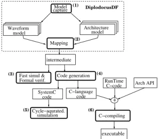
The extended methodology is depicted in Fig.2. It is composed of the following steps:
1) Abstract modelling DiplodocusDF consists of two DSML. One for architectures, which is briefly described in Sec-tion III-B1. A second one for waveforms, it is described in detail in section IV.
2) Mapping the waveforms to the selected architecture. 3) Formal verification by transforming the mapped
appli-cation into its formal representation. The extended lan-guage was specified such that retains the support of DIPLODOCUS [7] to formally verify functional or non-functional properties.
4) Code generation for final representation, either SystemC code or C-language code. Each operation from the wave-form is transwave-formed into a C-function, the C-functions are scheduled for execution according to the status of its input signals, but also according to the policy of a runtime environment, which manages the execution of the C-functions. C-functions are based on an API which abstracts the functionalities of the given SDR architecture. 5) Cycle-accurate simulation to validate functional require-ments and performance requirerequire-ments such as execution time, power consumption, etc.
6) C-compiling to generate the final executable code. It compiles the code generated automatically (C-language code), the runtime and the architecture API to generate a final executable.
Steps (1), (2), and (3) have been integrated into previous design exploration methodologies, but as noted in [8], [9], there remains a synchrony problem between the model and the final implementation, i.e., the final implementations does not reflect the initial model, specially since the development is done manually. Our methodology contributes to solve the synchrony problem by adding step (4), which is the automatic generation from the mapped model. It also contributes to make true the paradigm correct-by-construction, as the generated code was de-rived from a model that was formally verified. Although, it would be necessary to prove that the code generation mechanisms, and the runtime does not change the properties that were verified formally.
intermediate
SystemC code Formal verif. Fast simul &
C−language code RunTime C−code executable Code generation Mapping Model capture DiplodocusDF (5) (4) (3) (1) (2) (6) model Architecture model Waveform simulation Cycle−aqurated. Arch API C−compiling
Fig. 2: Proposed model-driven design methodology.
B. DiplodocusDF
DiplodocusDF is a domain specific modelling language based on UML. It extends the DIPLODOCUS profile [1] for the SDR domain. DiplodocusDF fosters re-usability and parallelism. Re-usability is a key aspect of diplodocusDF, it is possible to define components that can be used in any application for any SDR architecture that supports that particular operator. This is possible thanks to the mixture of declarative/imperative description capa-bilities. The network of operations and the data dependencies among them are described in a declarative manner, using the component based UML profile, while the internal behaviour of each operation is described in an imperative way, using UML activity diagrams. A second key aspect of diplodocusDF is that is exposes the potential parallelism in a waveform. DiplodocusDF extends the DIPLODOCUS concepts of components, ports and data-abstraction. It also extends the semantics of several activity diagram operators.
1) SDR architecture model: We extended the architecture profile from [1] to support the particularities found in SDR architectures, which were described in Section II. The exten-sions include: (1) direct data transfer between processing nodes
(stream behaviour), (2) hardware accelerators (HWA) can execute multiple tasks, sequentially, one after the other with no time sharing. Normally, HWA are seen as components which can only execute one task, but in SDR architectures they tend to be highly configurable, (3) storage nodes are divided into memory buffers of different characteristics.
2) Mapping waveforms to SDR architectures: The mapping of the waveform to the SDR architecture is done manually by the user, but directed by a set of rules that ensure a well formed model. There are general rules applicable for any given architecture, for example, (a) routing operations can be mapped only to general purpose processing nodes, (b) transformation operations can be mapped to any processing node, (c) links are mapped to buffers (which belong to a memory node), etc. The mapping rules will be described formally and the simulation tool will be extended accordingly
C. Prior Art
UML is well established as a good base for MDD method-ologies, papers [10] and [9] discuss the potential of UML for model-driven design, in general for embedded systems (control, communications, etc.). The authors of [11], [12], [13] propose UML/MDD methodologies to generate the components of data-flow systems, without considerations of the software components. In our case, the hardware components are already available, and we search to generate the coordination software. The paper [14] proposes a UML based methodology for code generation of em-bedded applications. It describes a series of transformations into intermediate languages and assumes a last transformation into executable code. It considers only monoprocessor architectures, while nowadays SDR platforms are multiprocessor based, either homogeneous or heterogeneous. The papers [15], [16] propose MDD/MARTE methodologies for general embedded applica-tions. A too general modelling language leads to complex models which are difficult to maintain, and therefore get abandoned. We define in this paper a domain-specific modelling language for SDR systems, which can be considered data-flow systems. In fact, UML lacks the basic constructs for data-flow applications, this was already identified by the authors of [17], who studied the possibility to integrate synchronous data-flow models with UML and proposed a data-flow notation with rather documentation purposes. The paper [18] presents an approach to use activity diagrams of UML 2.0 for business data-flow applications, this proposal is similar to ours in covering flat control-flow/data-flow, also suggested in [19] for data-flow models in general, but their objective is only modelling and no concepts of synthesis are taken into account. Although this paper focuses on the modelling language, its precise description involves not only expressiveness, but also transformation semantics into formal and deployment languages. The paper [20] proposes a methodo-logy based on UML/MARTE/CCSL for synthesis of data-flow applications. Its methodology considers the time constrains of data-flow applications to statically generate code, as it is related to the synchronous data-flow language SIGNAL. The case of SDR systems is a particular case of synchronous data-flow, as the number of processes samples is known, but the execution of some operations depends on the results of previous operations,
this makes no possible to generate a static scheduling solution. Our methodology considers this aspect and the scheduling so-lution is an hybrid one, mixing event-driven and time-driven operations. Other non UML-based MDD methodologies have been proposed for SDR systems. For example, the paper [21] proposes a proprietary data-flow XML language, used to describe the waveforms and the parametrizable operators (they call them kernels). They do not really separate both models, forcing to have a generation mechanism specific for each target platform. The papers [22], [23] describe MDD methodologies based on the proprietary language/tool Simulink/Matlab. This is a handy ap-proach, as it is common that communications engineers described their algorithms in Matlab for functional validation. However, simulink does not allows formal analysis of its models, this extends the phase of test in the development process. Also, it is not possible to extend the Simulink’s transformation mechanisms for different execution architectures.
Resent design methodologies have shows positive results on formal design exploration. The output of these methodologies is a model with properties that are formally proved. Extending these methodologies to automatically convert its output model into deployment language contributes to develop systems which are correct-by-construction. This paper presents such an extended methodology for the domain of software defined radio.
IV. DIPLODOCUSDF WAVEFORM MODEL
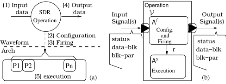
A waveform in DiplodocusDF is modelled as a network of operations which exchange signals through unidirectional links, as seen in Fig.1. As mentioned in section II, the waveforms are in charge of controlling the execution of SDR architectures. Consequently, each waveform operation controls the execution of a SDR operator. Our waveform model considers also the actual execution of the SDR operator in an abstract way, with no details on the behaviour of the SDR operator, but as an atomic task that is fired for execution.
P1 P2 Pn (a) SDR data Operation (1) Input (4) Output data (2) Configuration Arch (3) Firing (5) execution r (b) Operation Signal(s) Input Signal(s) Output Waveform status data−blk
blk−par blk−pardata−blk status V Firing and Config. Af Ax Execution
Fig. 3: SDR operation model.
A. Signals
The signals model the data-blocks produced/consumed by the SDR operations. The signals are put in a link through ports. The ports are tuples composed of several elements such as: name, direction, abidance, status, data-block, and data-block parame-ters. Some port elements are set during execution time, such as status, data-block and data-block parameters. These elements define a signal. Other port elements are set at declaration time, including: name, direction, and abidance. The name identifies the port, and is used for code-generation purposes. The direction
flag is used to identify the producer port from the consumer. When the abidance flag is set to true, the port’s output signals are marked as constant.
During execution, the signals are marked as new after being produced, and are marked old when they are consumed. If the signal was marked as constant, it will not be marked as old after being consumed, therefore it can be reused. The signal carries information about its data-block (data-block parameters), for example block size and block data type. This information can be used by the consumer operation to adjust its behaviour. It is possible to have as many data-block parameters as necessary for a particular waveform.
B. Operations
A waveform is composed of a number of SDR operations that have data dependencies among them. When the data dependen-cies of a SDR operation are met, the operation is eligible for execution. The execution process of a SDR operation follows the next steps: (1) Wait for the inputs conditions, (2) setting the execution parameters, (3) firing the execution, and (4) inform when the output data is available. The model also considers the execution of the SDR operation, which would be step (5) in the overall process. Fig.3-(a) depicts graphically the execution process of an operation. In diplodocusDF, steps (1), (2), (3), and (5) are described in a single sequential task called firing. Step (4) is described in a different task called execution. The two tasks are differentiated as it is possible to execute them by different processing elements. The two tasks are depicted as components of a SDR operation in Fig.3-(b), where Af is the firing task and Ax is the execution of the SDR operation is requested through
the signal r. The set of variablesV is accessible by both tasks, helping to control the behaviour of the operation.
The execution of an operation starts when its fire rule is met. This means that the input signal is marked as new. For operations with more than one input signals, one of two rules can be used, (1) and rule, where all the input signals are new , (2) or rule, where at least one of the signals is new . For all cases, it is necessary that the output signal(s) be marked as old.
We identify two types of operations: (1) transformation operations, which in fact transform the inputs into different outputs, e.g., Component-wise addition, Fast-Fourier transform. (2) routing operations which help to decide what signals have to be activated, thus what operator will be executed in order to achieve a desired behaviour, the routing operations are used to describe control structures, e.g., Loop and conditional structures. Routing operations do not have an execution task associated.
1) Activity diagrams: The behaviour of the operations is de-scribed using UML activity diagrams (ADs). ADs are defined by the OMG as graphical representations of step-by-step activities and actions that are part of a logical process. Activities and actions are called in general ”instructions” along this paper. In diplodocusDF we use ADs to describe the behaviour of each SDR operation that belongs to a waveform. In fact, they require two activity diagrams, one for firing and a second one for execution:
• Ax describes the actual execution of the operation. The
instructions used in this activity diagram are described in
the Table I.
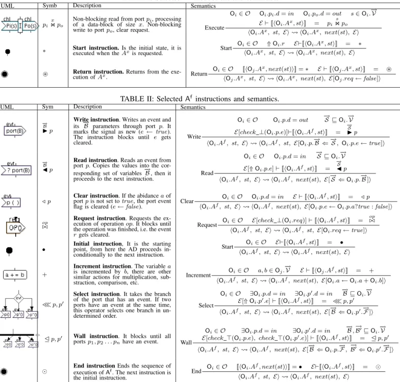
• Af describes the parameter generation and fire of operation execution. The Af instructions are described in the Table II. The firsts columns of tables II and I show the activity diagram (AD) instructions extended for SDR applications. The second columns show its representation, which will be used to state formally the diplodocusDF syntax and operational rules, for example,
− →
B
◮ p represents the write instruction, which writes a signal to the port p with a vector of parameters −→B . The thirds columns give the semantics of each activity diagram instruction. For illustration purposes of ADs use and operation, we use the activity diagram DMA.Af from Fig.5 (in the second dotted square). The first instruction is the initial instruction denoted by • from where the AD proceeds to the next state, the read instruc-tion denoted by
−→ O∫
◭ DM A in, where the execution of DMA.Af
AD blocks until receiving a signal through the DM A in port. Once the signal is received, the Os variable receives the value carried by the first (and only) parameter DMA.DM A in.−→B , and the AD proceeds to the next instruction, which is the request instruction denoted byxDM A⊲⊳ . The request instruction starts the execution of DMA.Ax.
C. Waveform syntax
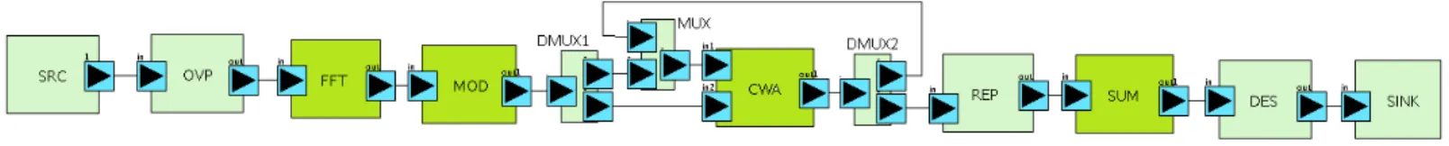
We describe in this section the formalisation of our proposed UML profile DiplodocusDF waveform. The Fig.4 shows an example of waveform, which model the Welch periodogram detector application, discussed in Section V.
1) Notations: We introduce some notations which will be used along the formal description of diplodocusDF. We denote a tuple with n elements byhe0, e1, ..., eni. Given a tuple S, the
ith element is reached by S.e
i. We represent a vectorA by − → A . − →
A ⊑−→B is true if the vector −→A is sub-vector of −→B . −→A ⊑ V is true if all the elements of vector−→A are found in V.
We denote by ⇑ a (resp. ⇓ a) a boolean indicating a rising (resp. falling) edge on a signal a.
We denote by v : τ the fact that variable v has been defined with the particular type τ .
We assume each instruction in an activity diagram is uniquely tagged with a label st. The label of the instruction which follows st in the activity diagram can be fetched with next(st).
We also provide auxiliary functions: check ⊥(a) (resp. check ⊤(a)) that returns true when a = false (resp. a = true) otherwise it returns false. We use ← to denote the assignment of a value to a variable or flag. We use⇐ to denote the multiple assignment. We also use a= cond?b : c to denote that the variable a gets the value b if the condition cond is true, else it gets c. Definition 1. Waveform A waveform is a network of operations
interconnected by links, W= hO, Li
The operations form a hierarchical collection of composite and primitive (basic) operations. As mentioned in Section IV-B, the basic operations can be the routing operations or data transfor-mation operations, i.e.,O = Ob∪ Oc and Ob= Ot∪ Or.
• Data transformation operations ∀Ot ∈ Ot, Ot =
hAf
, Ax
Fig. 4: DiplodocusDF waveform for Welch periodogram detector. – An activity diagram Af for firing process.
– An activity diagram Ax for execution process.
– A set of portsP. Where ∀P ∈ P, P = hl, d, a, e, c, Bi, consisting of:
∗ l is a label from the alphabet A. ∗ d is a direction flag with d ∈ {in, out}.. ∗ a is an abidance flag a ∈ {true, false}.. ∗ e is a status flag, with e ∈ {true, false}. ∗ c is an abstract data-block channel.
∗ −→−→B is a vector of data-block parameters, where ∀Bi ∈
B , Bi: t ∈ {int, char}. B can be empty.
– A set of local variables V, where ∀V ∈ V, V : t ∈ {int, char }. These variables are used in Ax
and Af. – a flag req, with req∈ {true, false}.
• Data routing operations. The data routing operation is
similar to the transformation operation, except that it does not have execution activity diagram. So,∀Or
∈ Or, Or
= hAf
,P, V, reqi.
• Composite operations. ∀Oc ∈ Oc, Oc = hWc, Pc, Vci
consisting of:
– Wc is a set of waveforms as defined in Definition 1.
– Pc is a set of ports.
– Vc a set of variables.
• Links. A link defines a data dependency between two
operations.∀L ∈ L, ∃O, O′∈ O, L ={O.p, O′.p′}.
By abuse of notation we denote by O.p the fact that p∈ O.P. To define a hierarchical structure we need the concept of inner port, which dictates the direction of the data dependency modelled by the link. If a port is not an inner port, then it is an outer port.
Definition 2. Inner port. Let ∃Oi∈ Oc be an operations such
that Oi = hWi,Pi,Vii. If ∃Oj ∈ O such that Oj ∈ Wi.O and
∃ L ∈ L L = {Oi.p, Oj.p′}, then Oj.p′ is called the inner port
of L.
The inner port concept is attached to the link, therefore we say ”the inner port of L”.
The linking of operations is driven by rules. For two operations which are not contained one in the other, a link between them shall include ports with different directions, we apply the rule of complementary ports. In fact, the values of the parameters l, d, and a of the most internal ports are declared by the user, while the outer ports inherit the values from the inner ports.
Rule 1. Complementary ports Let Oi, Oj ∈ O be two
oper-ations. If ∃ L = {Oi.p, Oj.p′} and L has no inner port, then
Oi.p.d6= Oj.p.d.
The ports can be part of only one link, i.e., broadcast is not permitted. We follow the Point-2-Point rule in this case. Rule 2. Point-2-Point Let L and L′ two links. If ∃O
i.p∈ L ∧
Oi.p∈ L′ and if O
j.p′ ∈ L ∧ Ok.p′∈ L′ are both inner ports or
both outer ports then L= L′.
To connect two ports they should have the same number of function parameters and the corresponding type of each parameter should be the same. We follow the matching ports rule in this case.
Rule 3. Matching ports Let Oi and Oj two operations. If
∃ L ∈ L such L = {Oi.p, Oj.p′}, then Oi.p. − → B = Oj.p. − → B and ∀k, Oi.p.Bk: t = Oj.p.Bk: t.
For composite operations, the direction of ports is computed recursively form the inner ports.
Rule 4. Direction inheritance of ports Let Oi ∈ Oc be an
operation such that Oi = hWi,Pi,Vii. Let Oj ∈ O be an
operation such that Oj ∈ Wi. If ∃ L = {Oi.p, Oj.p′}, then
Oi.p.d= Oj.p′.d.
Among the ADs instructions we find read and write, denoted as − → S ◭p and − → S
◮p respectively (see Table II). The instructions mean that the operation reads/writes a signal from/to the port p, the signal has a vector−→S of data-block parameters. The following rule enforces that the number of variables (
− → S ) written (resp. read) should match in number and type, the data-block vector of the writing (resp. reading) port (Oi.p.
− →
B ).
Rule 5. Signal write parameters (resp. Signal read
parameters) ∀Oi ∈ O, if ( − → S ◮ p) ∈ Oi.Af (resp. ( − → S ◭ p) ∈ Oi.Af) where − → S ⊑ Oi.V then − → S = Oi.p. − → B and ∀k,−→Sk: t = Oi.p. − → Bk: t. D. Waveform semantics
Executing an SDR operation consists, on each step, in pro-cessing the instructions which are part of the operation’s activity diagram(s) (ADs). This processing can modify the value of variables and flags in the environment. It can also change the operation itself as it may change the activity state if a transition occurs.
We propose a SOS semantics for the language. This semantics expresses precisely the sequence of actions involved in the processing an instruction of an AD. It is made of rules with the following general form: E ⊢ [[hA, st, Ei]], hA, st, Ei hA, st′,E′i
TABLE I: Selected Ax
instructions and semantics.
UML Symb Description Semantics
pi x
⋊ ⋉po
Non-blocking read from port pi, processing
of a data-block of size x. Non-blocking
write to port po, clear request. Execute
Oi∈ O Oi.pi.d= in Oi.po.d= out s∈ Oi.−→V E ⊢ [[hOi.Ax, sti]] = pi s ⋊ ⋉po hOi.Ax, st, Ei hOi.Ax, next(st), Ei
∗ Start instruction. Is the initial state, it isexecuted when the Axis requested. Start
Oi∈ O ⇑ Oi.r E⊢[[hOi.Ax, sti]] = ∗
hOi.Ax, st, Ei hOi.Ax, next(st), Ei
⊛ Return instruction. Returns from the
exe-cution of Ax. Return
Oi∈ O [[hOj.Ax, next(st)i]] = ∗ E ⊢ [[hO
j.Ax, sti]] = ⊛
hOj.Ax, st, Ei hOi.Ax, next(st), E[Oj.req← false]i
TABLE II: Selected Af instructions and semantics.
UML Sym Description Semantics
− → B
◮p
Write instruction. Writes an event and its −→B parameters through port p. It marks the signal as new (e← true). The instruction blocks until e gets cleared. Write Oi∈ O Oi.p.d= out −→S ⊑ Oi. − → V E[check ⊥(Oi.p.e)]⊢[[hOi.Af, sti]] =
− → S
◮p
hOi.Af, st, Ei hOi.Af, st, E[Oi.p.−→B ⇐−→S , Oi.p.e← true]i −
→ B
◭p
Read instruction. Reads an event from port p. Copies the values into the cor-responding set of variables−→B , then it proceeds to the next instruction.
Read
Oi∈ O Oi.p.d= in −→S ⊑ Oi.−→V
E[⇑ Oi.p.e] ⊢ [[hOi.Af, sti]] = − → S ◭p hOi.Af, st, Ei hOi.Af, next(st), E[ − → S ⇐ Oi.p. − → B ]i
⊳ p Clear instruction. If the abidance a ofport p is not set to true, the port event flag is cleared (e← false). Clear
Oi∈ O Oi.p.d= in E ⊢ [[hOi.Af, sti]] = ⊳ p
hOi.Af, st, Ei hOi.Af, next(st), E[Oi.p.e← Oi.p.a?true : false]i op
⊲⊳
Request instruction. Requests the ex-ecution of operation op. It blocks until the operation was finished, i.e. the event r gets cleared.
Request Oi∈ O E[check ⊥(Oi.req)] ⊢ [[hOi.A
f, sti]] = op⊲⊳
hOi.Af, st, Ei hOi.Af, st, E[Oi.req← true]i
• Initial instruction, It is the startingpoint, from here the AD proceeds in-conditionally to the next instruction.
Start Oi∈ O E⊢[[hOi.A
f, sti]] = •
hOi.Af, st, Ei hOi.Af, next(st), Ei
+
Increment instruction. The variable a is incremented by b, there are other similar actions for multiplication, sub-straction, comparison, etc.
Increment
Oi∈ O a, b∈ Oj.
− →
V E ⊢ [[hOj.Af, sti]] = +
hOi.Af, st, Ei hOi.Af, next(st), E[Oi.a← Oi.a+ Oi.b]i
≪p, p′
Select instruction. It takes the branch of the port that has an event. If two ports have an event at the same time, this operator selects one branch in un-determined order. Select Oi∈ O ∃Oi.p.d= in ∃Oi.p′.d= in − → B ⊑ Oi. − → V E[⇑ Oi.p′.e] ⊢ [[hOi.Af, sti]] = ≪p, p′
hOi.Af, st, Ei hOi.Af, next(st), E[−→B ⇐ Oi.p′.−→F ]i
Ep, p′ Wall instruction. It blocks until all
ports p1, p2. . . pnhave an event. Wall
Oi∈ O ∃Oi.p.d= in ∃Oi.p′.d= in −→B ,
− → B′
⊑ Oi.−→V
E[check ⊤(Oi.p.e), check ⊤(Oi.p′.e)] ⊢ [[hOi.Af, sti]] = Ep, p′
hOi.Af, st, Ei hOi.Af, next(st), E[−→B ⇐ Oi.p.−→F ,
− → B′
⇐ Oi.p′.−→F ]i
⊙ End instruction Ends the sequence ofexecution of Af. The next instruction is
the initial instruction.
End Oi∈ O [[hOi.A
f, next(st)i]] = • E⊢[[hO
i.Af, sti]] = ⊙
hOi.Af, st, Ei hOi.Af, next(st), Ei
Executing an instruction labelled st, within an environmentE (a binding of variables and flags to values) through an activity diagram A produces a new environment,E’ and a new label st’. For example, the write instruction rule WRITE from Table II is executed if the current state (st) of the fire activity diagram (Oi.Af) corresponds to the write instruction (
− →
S
◮p) and the status flag is set to false(check ⊥(Oi.p.e)) and the direction flag of the
port on which is done the writing is set to out (Oi.p.d= out),
then the signal parameters are wise-copied to the port parameters (Oi.p.
− →
B ⇐ −→S ), the event flag Oi.p.e is set to the true value
(Oi.p.e ← true). The activity diagram remains blocked in the
same instructionWRITEuntil the status flag of the writing port is
set back to false. The purpose of this behaviour is to prevent the execution of the producer operation before its previous output was consumed.
We take the wall instruction from Table II as a second example. We use the wall instruction in operations such as CWA from Fig.4. CWA has two inputs, and it is necessary to have new signals in both inputs to start execution. The WALL rule is executed when the current state (st) of the fire activity diagram (Oi.Af) corresponds to the wall instruction (E p, p′), and the
direction flags are both set to in(Oi.p.d= in and Oi.p′.d= in),
and the status flags are both set to true (check ⊤(Oi.p.e) and
parameters belong to the set of variables (−→B ,−→B′ ⊑ O i.
− →
V ). The execution of the WALL instruction rule copies by position the contents of the port parameters (−→B and−→B′) to the corresponding
variables (Oi.
− →
V ).
E. Data Transfer
The SEND rule is used to propagate a signal through a link. Every time a WRITE rule is applied on a port Oi.p. This latter
is marked as new (Oi.p.e← true) and the signal is propagated
by theSEND rule through the link L= hOi.p, Oj.p′i to which it
is attached. This rule will set to true the status flag Oj.p′.e, and
will copy the block parameters by position among both ports. Our model does not consider infinite storage, therefore the operations should not produce a new signal if the previous signal has not been consumed yet. Thus the WRITE rule blocks until the sent signal was marked as old (Oj.p′.e ← false) by the ACK rule.
This prevents the operation from continue processing signals.
Send Oi, Oj∈ O L= {Oi.p, Oj.p′} Oi.p.d= out ⇑ Oi.p.e Oj.p′.−→F ⇐ O i.p. − → F Oj.p′.e← true
When a signal is consumed theCLEAR rule marks this signal as old in the consumer operator. This setting is propagated by the ACK rule through the link to the producer operator.
Ack
Oi, Oj∈ O L= {Oi.p, Oj.p′} Oi.p.d= in ⇓ Oi.p.e
Oj.p′.e← false
V. EXAMPLE: WELCH PERIODOGRAM DETECTOR
This section demonstrates the use of DiplodocusDF by de-scribing the application: Welch periodogram detector [24]. Welch periodogram is used for opportunistic spectrum sensing, it helps to identify the significance of the frequency contributors to a wireless signal by calculating the energy of the sub-bands of interest (statistics). The calculated energy is then compared to a designated threshold (decisions).
The Welch detector is described in the Algorithm 1 and its DiplodocusDF waveform model is shown in Fig.4. The operations in the Algorithm 1 lines 3, 4, 5, and 10 correspond to common SDR operations, these operations are part of a library of DiplodocusDF operation models that the user can use as is, they correspond to the transformation operations FFT, MOD, CWA, and SUM of Fig.4. The activity diagrams of the Fast-Fourier transform FFT.Af and FFT.Ax, are shown in the Fig.5 (last dotted square), the diagrams for the other 3 operations are similar. The overlapping operation in the Algorithm 1 line 2 reorganizes the r input, to deliver data segments overlapped by Ospositions.
It is a routing operation (as it does not transform the data), which is particular to this waveform and has to be described by the user. Its activity diagram OVLP.Af is also shown in Fig.5.
The data loop operation in the Algorithm 1 line 1 is modelled in DiplodocusDF with the mux-like operations DMUX1, MUX, and DMUX2. This arrangement allows to load the CWA with two valid signals before starting execution for the first time. Another solution would be to make a first CWA operation between a valid signal and a constant zero signal. These mux-like operations are
described in such a way that they activate the right output signal according to the number of input signals received. For example, DMUX2 will activate the feedback signal as long as the number of its input signals be less than m, then it will activate the signal going to the REP operation.
The routing operation in Algorithm 1 line 8 does not imply a data loop, but rather the multiple use of the Rs signal. Rs is
accessed L times at different offsets. The REP operation in Fig.4 models this behaviour. It will not mark as old its input signal at each execution but after L executions. At each execution it will mark as new its output signal, which will enable the execution of the SUM operation. REP is a routing operation as it does not transform its inputs but only enables in a particular way its outputs. DES is a routing operation. It decides if given sub-band is occupied by comparing the outputs from SUM to predefined decision levels. The outputs from DES (decisions) are sink at the SINK operation.
The Fig.5 shows the activity diagrams for the first four operations of Welch diplodocusDF (SRC, DMA, OVP, and FFT) shown in Fig.4:
Algorithm 1: Welch detector algorithm in : m number of segments.
in : r input data
in : rkkth input data segments of size Ns, k = 1,2,. . . ,m.
in : L number of sub-bands of interest. in : fi
of f is the list of sub-band central frequencies.
in : Liis the list of sub-band widths.
in : Ywd is the list of sub-band thesholds.
out : Twd is the list of statistics per sub-band.
out : Dwd list of decisions per sub-band.
tmp: X, Y, Z, Rsbuffers of size Ns. tmp: k, j control counters. 1 for k← 1 to m do 2 rk← [r(kOs), r(1 + kOs), . . . , r(kOs+ Ns+ 1)]; 3 X← FFT(rk); 4 Y ← MOD(X); 5 Z← CWA(Z, y); 6 end 7 Rs←mZ ; 8 for j← 1 to L do 9 start← fof fj −L j i 2 ;
10 Twdj ← SUM(Rs, start, start+ Lji);
11 if Twdj > Ywdj then 12 Dwdj ← 1; 13 else 14 Dj wd← 0; 15 end 16 end
VI. CONCLUDING REMARKS AND FUTURE WORK
In this paper we address the challenge of developing complex SDR systems in an efficient way. We propose a model-driven design methodology that isolates the description of the SDR applications from its implementation details. Our methodology contributes to develop correct-by-construction SDR systems.
We extended DIPLODOCUS to DiplodocusDF in order to support SDR applications. For this, we added data-flow/KNP alike semantics. This allows to express all possible parallelism and results in deterministic behaviour as in KNP. We added SDR semantics by extended the task operator from DIPLODOCUS to express complex transformation operands. They are now composed of two activity diagrams, one of them resolves the
SRC.Af
1
OVLP.Af FFT.Af
DMA.Af
DMA.Ax FFT.Ax
Fig. 5: Example activity diagrams from Welch periodogram waveform. fire rule and request the execution of the operation. The second
activity diagram represents the actual execution of the operation, which can be delayed with respect to the request. The delay can happen if the operator is being used by another operation. We also extended the notion of abstract channels to the concept of SDR signals. DiplodocusDF supports also automatic code generation from the abstract representation to C-language.
This paper focuses on the formal description of the DiplodocusDF language and its semantics. Thanks to this de-scription, we can transform our models into formal representation (FSM, LOTOS, etc), which can be analysed and used to perform formal verification by model-checking. We can validate safety and functional properties (e.g. absence of deadlock) .
Currently, we are developing the code generation mechanisms. The final code is composed of (1) a runtime environment (the one that executes the rules), (2) a set of functions that reflect the behaviour of the operations, (3) a platform specific architecture-support package in the form of an API.
As part of the future work, we will develop a mechanism for automatic mapping based on constraint rules, this will re-quire designing a constraint profile to direct the mapping of a waveform to a SDR architecture. Also, we will define another profile to describe performance requirements (execution time, power consumption, etc). The information from the performance requirements model will be added to the mapped model and will be considered for the formal analysis.
REFERENCES
[1] L. Apvrille, W. Muhammad, R. Ameur-Boulifa, S. Coudert, and R. Pacalet, “A uml-based environment for system design space exploration,” in Elec-tronics, Circuits and Systems, 2006. ICECS ’06. 13th IEEE International Conference on, dec. 2006, pp. 1272–1275.
[2] D. Lattard, E. Beigne, F. Clermidy, Y. Durand, R. Lemaire, P. Vivet, and F. Berens, “A reconfigurable baseband platform based on an asynchronous network-on-chip,” Solid-State Circuits, IEEE Journal of, vol. 43, no. 1, pp. 223–235, jan. 2008.
[3] D. Nussbaum, K. Kalfallah, R. Knopp, C. Moy, A. Nafkha, P. Leray, M. De-lorme, J. Palicot, J. Martin, F. Clermidy, B. Mercier, and R. Pacalet, “ropen platform for prototyping of advanced software defined radio and cognitive radio techniques,” in Digital System Design, Architectures, Methods and Tools, 2009. DSD ’09. 12th Euromicro Conference on, 27-29 2009, pp. 435–440.
[4] G. Radio, “The gnu software radio.” [Online]. Available: http://gnuradio.org [5] T. Ulversoy, “Software defined radio: Challenges and opportunities,”
Com-munications Surveys Tutorials, IEEE, vol. PP, no. 99, pp. 1–20, 2010. [6] A. Tribble, “The software defined radio: Fact and fiction,” in Radio and
Wireless Symposium, 2008 IEEE, Jan. 2008, pp. 5–8.
[7] D. Knorreck, L. Apvrille, and R. Pacalet, “Formal system-level design space exploration,” in New Technologies of Distributed Systems (NOTERE), 2010 10th Annual International Conference on, 31 2010-june 2 2010, pp. 1–8. [8] D. Schmidt, “Guest editor’s introduction: Model-driven engineering,”
Com-puter, vol. 39, no. 2, pp. 25–31, feb. 2006.
[9] B. Selic, “The pragmatics of model-driven development,” Software, IEEE, vol. 20, no. 5, pp. 19–25, sept.-oct. 2003.
[10] R. France, S. Ghosh, T. Dinh-Trong, and A. Solberg, “Model-driven development using uml 2.0: promises and pitfalls,” Computer, vol. 39, no. 2, pp. 59–66, feb. 2006.
[11] Y. Zhu, Z. Sun, W.-F. Wong, and A. Maxiaguine, “Using uml 2.0 for system level design of real time soc platforms for stream processing,” in Embedded and Real-Time Computing Systems and Applications, 2005. Proceedings. 11th IEEE International Conference on, aug. 2005, pp. 154–159. [12] J. Vidal, F. de Lamotte, G. Gogniat, J.-P. Diguet, and P. Soulard, “Uml
design for dynamically reconfigurable multiprocessor embedded systems,” in Design, Automation Test in Europe Conference Exhibition (DATE), 2010, march 2010, pp. 1195–1200.
[13] J. Vidal, F. de Lamotte, G. Gogniat, P. Soulard, and J.-P. Diguet, “A co-design approach for embedded system modeling and code generation with uml and marte,” in Design, Automation Test in Europe Conference Exhibition, 2009. DATE ’09., april 2009, pp. 226–231.
[14] G. Papadopoulos, “Automatic code generation: A practical approach,” in Information Technology Interfaces, 2008. ITI 2008. 30th International Conference on, june 2008, pp. 861–866.
[15] I. et al Perseil, “An efficient modeling and execution framework for complex systems development,” in Engineering of Complex Computer Systems (ICECCS), 2011 16th IEEE International Conference on, april 2011, pp. 317–331.
[16] M. Brun, J. Delatour, and Y. Trinquet, “Code generation from aadl to a real-time operating system: An experimentation feedback on the use of model transformation,” in Engineering of Complex Computer Systems, 2008. ICECCS 2008. 13th IEEE International Conference on, 31 2008-april 3 2008, pp. 257–262.
[17] P. Green and S. Essa, “Integrating the synchronous dataflow model with uml,” in Design, Automation and Test in Europe Conference and Exhibition, 2004. Proceedings, vol. 1, feb. 2004, pp. 736–737 Vol.1.
[18] H. St¨orrle, “Semantics of uml 2.0 activities with data-flow,” 2004. [19] J. Dennis, “Data flow supercomputers,” Computer, vol. 13, no. 11, pp. 48–
56, nov. 1980.
[20] H. Yu, J. Talpin, L. Besnard, T. Gautier, H. Marchand, and P. Le Guernic, “Polychronous controller synthesis from marte ccsl timing specifications,” in Formal Methods and Models for Codesign (MEMOCODE), 2011 9th IEEE/ACM International Conference on, july 2011, pp. 21–30.
[21] P. Kourzanov and H. Sips, “C modulo dsl,” in ITSLE 2011, 2011. [Online]. Available: http://www.pds.ewi.tudelft.nl/pubs/papers/itsle2011.pdf [22] M. Ahmadian, Z. Nazari, N. Nakhaee, and Z. Kostic, “Model based design
and sdr,” in DSPenabledRadio, 2005. The 2nd IEE/EURASIP Conference on (Ref. No. 2005/11086), sept. 2005, p. 8 pp.
[23] D. M. Schwall and D. S. Nagel, “Model-based waveform design for heterogeneous sdr platforms with simulink,” Communications, 2011. [24] A. Hekkala, I. Harjula, D. Panaitopol, T. Rautio, and R. Pacalet,
“Cooper-ative spectrum sensing study using welch periodogram,” in Telecommuni-cations (ConTEL), Proceedings of the 2011 11th International Conference on, june 2011, pp. 67–74.