HAL Id: hal-02491783
https://hal.archives-ouvertes.fr/hal-02491783
Submitted on 26 Feb 2020
HAL is a multi-disciplinary open access
archive for the deposit and dissemination of
sci-entific research documents, whether they are
pub-lished or not. The documents may come from
teaching and research institutions in France or
abroad, or from public or private research centers.
L’archive ouverte pluridisciplinaire HAL, est
destinée au dépôt et à la diffusion de documents
scientifiques de niveau recherche, publiés ou non,
émanant des établissements d’enseignement et de
recherche français ou étrangers, des laboratoires
publics ou privés.
R-Min: a Fast Collaborative Underactuated Parallel
Robot for Pick-and-Place Operations
Guillaume Jeanneau, Vincent Begoc, Sébastien Briot, Alexandre Goldsztejn
To cite this version:
Guillaume Jeanneau, Vincent Begoc, Sébastien Briot, Alexandre Goldsztejn. R-Min: a Fast
Col-laborative Underactuated Parallel Robot for Pick-and-Place Operations. IEEE 2020 International
Conference on Robotics and Automation (ICRA 2020), May 2020, Paris, France. �hal-02491783�
R-Min: a Fast Collaborative Underactuated Parallel Robot for
Pick-and-Place Operations
Guillaume Jeanneau
1, Vincent B´egoc
2, S´ebastien Briot
3and Alexandre Goldsztejn
3Abstract— This paper introduces an intrinsically safe parallel manipulator dedicated to fast pick-and-place operations, called R-Min. It has been designed to reduce the risk of injury during a collision with a human operator, while maintaining high speed and acceleration. The proposed architecture is based on a modification of the well-known planar five-bar mechanism, where additional passive joints are introduced to the distal links in order to create a planar seven-bar mechanism with two degrees of underactuation, so that it can passively reconfigure in case of collision. A supplementary passive leg, in which a tension spring is mounted, is added between the base and the end-effector in order to constrain the additional degrees of freedom.
A prototype of this new collaborative parallel robot is designed and its equilibrium configurations under several types of loadings are analyzed. Its dynamics is also studied. We analyze the impact force occurring during a collision between our prototype and the head of an operator and compare these results with those that would have been obtained with a rigid five-bar mechanism. Simulation results of impact during a standard pick-and-place trajectory of duration 0.3 s show that a regular five-bar mechanism would injure a human, while our robot would avoid the trauma.
I. INTRODUCTION
Since several years, collaborative robots have been gaining more attention due to the growing demand from the manufac-turing industry for flexible and cost-efficient production lines. Collaborative robots are intended to be used without safety fences and share a working space with nearby operators.
Designing robots that safely interact with humans requires validated criteria that indicate acceptable level of pain or injury. In [1], the authors provided an extensive summary of impact experiments from biomechanics and robotics liter-ature aiming at evaluating the severity of contacts with the human head and chest. Indeed, most of the experiments have been carried out for the needs of the automative industry, and thus focused on particularly sensitive body regions: head and chest. A widely used criterion is the Head Injury Criterion (HIC) [2], [3], that permits to evaluate brain damages due to the evolution of head linear acceleration. This index has also been widely applied to the study of physical human-robot interaction [4]–[7]. The standard technical specification ISO/TS 15066 integrates force and pressure thresholds for 1 G. Jeanneau is with the Laboratoire des Sciences du Num´erique de Nantes (LS2N), UMR CNRS 6004, at the ´Ecole Centrale de Nantes, 44321, Nantes, [email protected]
2 V. B´egoc is with the LS2N at Institut Catholique d’Arts et M´etiers, [email protected]
3 S. Briot and A. Goldsztejn are with the LS2N at the Centre National de la Recherche Scientifique (CNRS), 44321, Nantes, France. {Sebastien.Briot,Alexandre.Goldsztejn}@ls2n.fr
different body regions [8], based on experiments carried out on live test subjects [9].
These injury criteria help robot designers to identify the risks and the directions of improvement in the design of safer robots. A first approach was on designing robots with lighter architecture [10], [11]. However, these robots remain stiff and, despite their improved sensor system and control, they must operate at low-speed to be able to react fast enough to a collision. A complementary approach consists in developing mechanically compliant joints in order to obtain intrinsically safe robot arms. Indeed, compliance permits to reduce the peak force during a collision. This can be achieved using serial elastic actuators (SEA) [12], or preferably, variable stiffness actuators (VSA) [5], [13]–[15], whose stiffness can be adapted to different kind of tasks and keep a safe behaviour. However VSA integrate small actuators and thus lead to complex, heavy and costly mechanisms. Another approach consists in using torque limiters [16]–[19], that offer precise positioning in a normal operating mode, while allowing disengagement when a torque threshold is exceeded due to a collision. Such torque limiters have been for instance installed between a suspended manipulator and its end-effector in [20].
Most of the collaborative robots are of serial kinematic architectures, which constrains them to move at low speed in order to avoid injuring a human in case of collision, thus limiting their productivity. In order to increase the robot speed, parallel kinematic architectures [21] could be envisaged for collaborative robot design. Parallel robots are indeed famous for their great performance in terms of speed and acceleration [22], which are obtained because motors are mounted onto the base, thus allowing the design of very lightweight architectures.
Parallel robots have already been used for safe physical interactions. For instance, many haptic interfaces are made of parallel architectures [23]. In [24], the authors applied an hybrid force/position controller to a Delta robot in order to allow safe interactions. More recently in [25], a collaborative parallel robot for pick-and-place tasks has been proposed. It is based on a regular five-bar mechanism whose distal links have been replaced by links made of soft material so that they can deform in case of collision, avoiding transmitting energy during impact. This concept is interesting, however collisions with the robot were not simulated nor experimented, and we have little information to conclude about the robot safety when impacts occur.
In this paper, we present another concept based on the combination of:
• additional passive joints inside the parallel robot kine-matic chain, thus adding unconstrained degrees of free-dom (dof) and allowing the robot to reconfigure itself in case of impact,
• the use of a preload system which allows to passively
drive the unconstrained robot dofs and kinematically constrain its configuration.
We introduce a prototype based on this concept, called R-Min (acronym of Robot-Manipulator for safe physical Interactions), and analyze its behavior, especially when im-pacts occur with an operator.
II. KINEMATIC ARCHITECTURE DESCRIPTION AND
PROTOTYPING OFR-MIN ROBOT
As explained in the introduction, our goal is to create a robot with low risk of injury in case it collides with a human while being able to increase the robot speed with respect to traditional collaborative robots. Therefore, we propose the following concept, which is based on a modified regular five-bar parallel mechanism.
A. Description of the kinematic architecture
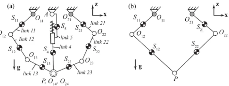
R-Min robot, presented in Fig. 1(a), is based on a modified five-bar parallel mechanism, which is widely used for pick-and-place operations at high speed [26]. This five-bar mech-anism (Fig. 1(b)) is a parallel robot made of two actuated
revolute joints located at points Oi1 (i = 1, 2), and three
passive revolute joints at points O12, O22 and P . All joint
axes are normal to the vertical plane P0: (O11, x, z). This
robot has two dofs, two motors, and is then fully actuated
and able to position the point P in the plane P0with a high
rigidity. While being able to perform at high-speed/high-accelerations (15 G of acceleration at the end-effector [26]), it is unable to collaborate with humans because of its high impedance.
As a result, in order to try to conserve the interesting speed properties while decreasing its impedance, we propose to modify the architecture of the five-bar mechanism as shown in Fig. 1(a). R-Min robot is thus composed of:
• a seven-bar parallel mechanism, with two actuated
revolute joints located at points Oi1, and five passive
revolute joints at points Oi2, Oi3 and P (i = 1, 2).
All joint axes are normal to the vertical plane P0 :
(A, x, z). This mechanism has four dof (instead of two for the five-bar mechanism), but only two motors. It is thus underactuated, with two unconstrained dofs. This seven-bar mechanism is thus of little practicability due to its null stiffness.
• therefore, we add a preload system made of a
kine-matic chain located between points A and P , which is composed of two passive revolute joints at A and
P , whose axis are normal to the plane P0, a passive
prismatic joint aligned along −→AP lying in P0, and a
compression spring exerting a compressing effort be-tween the points A and P . This preload system plays the same role as elastic elements introduced in the design of underactuated hands [27], i.e. it is added here in order
z P, O14, O24 z link 11 link 12 link 13 link 21 link 22 link 23 link 5 link 4 (a) (b) O 11 S 11 O 12 O13 O 23 O22 O 21 S 12 S 13 S 23 S 22 S 21 S4 S5 A x x g g P O 11 S 11 O12 O22 O 21 S 12 S22 S 21
Fig. 1. Kinematic chains of (a) R-Min robot, (b) a five-bar mechanism. Grey joints are the active joints.
to passively drive the unconstrained dofs of the robot and kinematically constrain its configuration. Preloaded springs could have been installed on one passive joint of the seven-bar mechanism, but this would have increased the mass of bodies that are likely to collide with an operator. The selected solution of a preload bar located inside the two legs of the seven-bar mechanism is safer, since it does not allow the operator to collide with this bar and in the same time permits to obtain a lightweight design of the external legs.
Indeed, this preload system is able to tense the passive
underactuated chain O12O13P O23O22, which is then more
rigid than in the case of the single seven-bar mechanism. However, it will have much less stiffness than a traditional five-bar mechanism, thus making it a good candidate for a collaborative parallel robot.
B. Design of a prototype
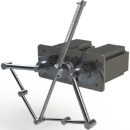
Based on the aforementioned kinematic architecture, the CAD design of a prototype was performed Fig. 2. In Table I, the lengths, inertia and positions of centre of mass extracted from CAD are provided. The links lengths have been chosen
such that, if the points Oi2, Oi3 and P (i = 1 or 2) were
aligned, the robot kinematics would be equivalent to the one of the five-bar mechanisms designed in [28], [29].
The key features for the design of this prototype are:
• all links are made in aluminum hollow tubes of circular
cross-section (external diameter of 30 mm, thickness of 5 mm for proximal links 11 and 21; external diameter of 20 mm, thickness of 2 mm for the other ones),
• passive joints have been made with bronze plain
bear-ings instead of ball bearbear-ings, to lighten the mechanism,
• a traction spring of stiffness 80 N/m and free length
0.2 m,
• two direct drive motors SIMOTICS S-1FL6 are used
(max torque 70 Nm, rated torque 23.9 Nm).
This prototype will serve in order to test the perfor-mance (in this paper, in simulation) of this new type of collaborative robot in terms of efforts transmitted during an impact. However, the system is underactuated and thus has different equilibrium configurations that vary with the external loadings. Thus, before testing the effects of collision, let us analyze its reconfiguration properties when different kinds of loads are applied on it.
Fig. 2. CAD modeling of the R-Min prototype. TABLE I
DIMENSIONS AND MASS PROPERTIES OF THE PROTOTYPE LINKS
Link Length Mass Inertia1 COM2 (i; j) li,j(m) mi,j(kg) Ji,j(kg.m2) xi,j(m) (1&2;1) 0.28 1.29 0.0168 0.0768 (1&2;2) 0.2 0.24 0.002 0.012 (1&2;3) 0.2 0.19 0.0015 0.01
(-;4) 0.82 0.42 0.0386 -0.31
(-;5) - 0.81 0.0026 0.023
1Moments of inertia around y are provided at the COM. 2Center of masses S
ij(Fig. 1(a)) are located on the lines OijOij+1. xi,jis the distance from Sijto Oij.
C. Self reconfiguration of the robot subject to external loads
1) Geometrico-static model: In what follows, we denote
as:
• qathe vector of the active joint coordinates representing
the motion of the motors located at O11 and O21,
• qdthe vector of the unconstrained coordinates; Here we
choose the motions of the revolute joints located at O12
and O22 as the unconstrained coordinates,
• qpthe vector of the remaining passive joint coordinates,
• p the position of point P , which is considered as the
end-effector location.
The parallel manipulator considered here is underac-tuated. Its implicit geometric model is therefore written
as: h(qa, qd, qp, p) = 0. For a fixed qa, there
ex-ists a dimension 2 manifold of solutions (qd, qp, p) to
h(qa, qd, qp, p) = 0, which is typical of underactuated
manipulators. The use of a spring constrains the mechanism to adopt one equilibrium configuration among a finite number of solutions within this manifold. These feasible solutions can be found by analyzing the local minima of the robot’s potential energy which corresponds to the robot’s equilib-rium configurations, i.e., by establishing its geometrico-static model.
The robot total potential energy plus the work associated to external forces fext is denoted by V (fext, qa, qd, qp, p).
Obviously, variables qa, qd, qp and p are related by the
geometric model h(qa, qd, qp, p) = 0. As a result, the
extrema of the potential energy can be found by applying the Lagrange conditions dedicated to finding extrema of functions under equality constraints:
∇V (qa, fext, qd, qp, p) + ∇h(qa, qd, qp, p) λ =0
h(qa, qd, qp, p) =0
(1) where λ is a vector of Lagrange multipliers. Here, gradients
include derivatives with respect to qd, qp and p. These
equations include all local minimizers, as well as maximizers and saddle points, which must be excluded by checking the
usual 2nd-order conditions for local minimality.
Next Section studies the equilibrium configurations of the robot under different kinds of loadings.
2) Analysis of the robot equilibrium configurations: We
have computed the prototype equilibrium configurations for several active joint configurations and loadings using the nu-merical solver IBEXSOLVE, which is distributed in the open source library IBEX (http://www.ibex-lib.org/). It implements a typical branch-and-prune algorithm [30], [31] relying on numerical constraint programming, i.e., contrac-tors like HC4 and interval Newton operacontrac-tors [32], which is able to compute all solutions of Eq. (1) with certification.
Results are shown in Figs. 3 and 4. It appears that, when the robot is subject to gravity effects only (Fig. 3(a)) or with an additional vertical force directed downwards (Fig. 3(b)),
which would be equivalent to the robot payload, points Oi2,
Oi3and P are near to be aligned, i.e. spring plus the external
loadings tense the passive bars. When a force with an upward component is applied either at the end-effector P or on a passive link (Fig. 3(c-d)), which would be equivalent to forces appearing during an impact, the robot encounters large displacements of its bodies during its internal reconfigu-ration. As a result, when the robot is subject to types of loadings appearing during the manipulation of objects (i.e. downward forces), the end-effector location is close to the one that would be attained by a five-bar mechanism with
distal links whose lengths are equal to `Oi2Oi3 + `Oi3P,
which is convenient for pick-and-place operations planning. On the contrary, when the robot is subject to types of loadings appearing during an impact with a human (i.e. forces with an upward component), the robot encounters large internal reconfigurations and thus, potentially, is likely to avoid transmitting a large part of its energy during impact thanks to this reconfiguration. These properties makes him a good candidate for safe physical interactions during pick-and-place operations.
It should be also noted that the analysis of several con-figurations showed that displacements of the point on which the force is applied are bigger when the force is applied on the distal links (Fig. 3(d)) rather than on the end-effector (Fig. 3(c)). So intuitively, an impact on the links may lead to less energy transmission during collision than an impact on the end-effector. This hypothesis will be proven later.
Finally, the robot may have several equilibrium configu-rations for a given active joint position and a given loading (Fig. 4). However, the aspects corresponding to each config-uration are generally separated, thus preventing the robot to
−0.4 −0.3 −0.2 −0.1 0 0.1 0.2 0.3 0.4 −0.5 −0.4 −0.3 −0.2 −0.1 0 x (m) z (m) −0.4 −0.3 −0.2 −0.1 0 0.1 0.2 0.3 0.4 −0.5 −0.4 −0.3 −0.2 −0.1 0 x (m) z (m) −0.4 −0.3 −0.2 −0.1 0 0.1 0.2 0.3 0.4 −0.5 −0.4 −0.3 −0.2 −0.1 0 x (m) z (m) −0.4 −0.3 −0.2 −0.1 0 0.1 0.2 0.3 0.4 −0.5 −0.4 −0.3 −0.2 −0.1 0 x (m) z (m) (a) (b) (c) (d)
Fig. 3. Equilibrium configurations of the prototype under different loadings in a symmetric configuration of the active links: equilibrium under gravity load (a) only, (b) plus a vertical descendant force of 20 N applied at the end-effector, (c) plus a diagonal ascendant force of 20 N applied at the end-effector, (d) plus a force of 20 N normal to link 12, applied at O13. Dotted black lines represent the distal links when they stay fully aligned.
−0.5 −0.4 −0.3 −0.2 −0.1 0 0.1 −0.5 −0.4 −0.3 −0.2 −0.1 0 x (m) z (m) (b) −0.5 −0.4 −0.3 −0.2 −0.1 0 0.1 −0.5 −0.4 −0.3 −0.2 −0.1 0 x (m) z (m) (a)
Fig. 4. Equilibrium configurations for the prototype in an asymmetric configuration of the active links: equilibrium under gravity load (a) plus a diagonal ascendant force of 20 N applied at the end-effector, (b) plus a force of 20 N normal to link 12, applied at O13.
jump from a configuration to another one.
III. ANALYSIS OF THE ROBOT DYNAMICS
In this Section, the dynamic model of the presented robot is described. The system being underactuated, this dynamic model is necessary in order to predict the state of the robot during its motion.
A. Dynamic model
The dynamic model of the underactuated parallel robot can be computed by following straightforwardly the approach proposed in [33]. It takes the following final form:
τ = M11q¨a+ M12q¨d+ h1(qa, qd, ˙qa, ˙qd) (2)
0 = MT12q¨a+ M22q¨d+ h2(qa, qd, ˙qa, ˙qd) (3)
where:
• τ is the vector of the motor input torques,
• M11, M12 and M22 are generalized inertia matrices,
all of dimensions (2 × 2); they are invertible as long as the robot does not meet any singularity [34]
• h1 and h2 are vectors containing the Coriolis and
centrifugal terms, gravity and friction effects, as well as spring effects; they are both of dimension 2.
0 0.1 0.2 0.3 Time (s) -0.4 -0.2 0 0.2 0 0.01 0.02 T ra c k in g e rr o r (m ) E n d -e ff e c to r c o o rd . (m ) Error norm x ref(t) x real(t) z real(t) z ref(t) z (m) -0.44 -0.46 x(m) 0 0.05 0.1 0.15 -0.05 -0.1 -0.15 I J Trajectory path
Fig. 5. Reference and actual trajectory achieved by the robot end-effector (left-hand side scale); Tracking error (right-hand side).
For a known active joint trajectory (qa, ˙qa, ¨qa), the
inverse dynamic model of the robot allows the computation
of the unconstrained joint motion (qd, ˙qd, ¨qd) from the
resolution of the nonlinear ODE (3). Once this motion is known, the input torques τ can be deduced from Eq. (2). B. Robot dynamic behavior in a pick-and-place operation
Based on the parameters provided in Tab. I, the inverse dy-namic model of our robot has been computed and simulated along a reference trajectory presented in Fig. 5.
This trajectory, which is a typical pick-and-place trajectory characterized by an horizontal displacement of 305 mm and a variation of altitude of 25 mm, was defined for the motion of the end-effector of a 2-dof high-speed fully actuated robot designed in [35]. Here, we use this trajectory in order to compute a reference trajectory for the active joints by the use
of the inverse kinematics, assuming that the points Oi2, Oi3
and P would be perfectly aligned for both legs. As a result, due to its underactuation and despite the preload mechanism, the end-effector of the robot will not be able to perfectly follow this reference trajectory. The tracking error depends on the stiffness of the spring of preload system.
The dynamic model is simulated using this reference trajectory. The output error of the end-effector position is presented on Fig. 5. The robot follows the input trajectory thanks to the spring with a maximal error of around 2 cm. This seems big, but this issue can be solved by using adequate controllers, like sliding modes [36].
Next section deals with the analysis of the robot during an impact.
IV. ROBOT IMPACT MODELLING AND ANALYSIS
In this Section, the aptitude for safe physical interaction of the presented robot is analyzed and compared with those of the five-bar mechanism. In this vein, the severity of a transient physical contact between the robot and a human head is evaluated through simulations.
A. Description of the simulation protocol
In order to evaluate the behaviour of R-Min robot in case of a collision with a human, simulations were carried out using the software ADAMS. Two models of robots have been developed, the model of our collaborative robot and
of an equivalent five-bar mechanism, in order to evaluate the interest of the proposed concept.
The ADAMS model of the collaborative robot is based on the prototype presented in Fig. 2 and uses the geometric, mass and inertia parameters given in Tab. I. The ADAMS model of the five-bar mechanism is obtained from the model of the collaborative robot, but by imposing the revolute joints
at points Oi3(i = 1, 2) to be blocked. Moreover, the preload
system was removed for fairer comparison purpose. In all presented simulations, we imposed that the five-bar mechanism follows the reference trajectory shown in Fig. 5 from point I to point J . In an industrial context, for small payloads (a few grams), it is pretty standard that a robot performs this trajectory (two-ways) several times per second (3 to 4 times per second) [35], [37]. Here, we limit the velocity along the trajectory, which is too fast in case of an impact with an operator, and we allow the robots to perform a one-way trajectory in 0.3 s, which is still much faster than standard trajectories performed by serial collaborative robots. We will see later that this new speed is already high enough so that an impact with a human and a rigid five-bar could cause trauma.
For the collaborative robot, we replayed the same trajec-tory, but in the joint space. Obviously, due to its underactu-ated nature and despite the preload mechanism, the trajectory followed by its end-effector cannot be exactly the reference trajectory. However, the end-effector velocities of both robots are close enough to allow comparisons of impact effects.
In what follows, we choose to investigate a contact be-tween the robot and a human head, since it is one of the most critical body parts to be protected from trauma. The head is modeled as a ball of radius R = 0.1 m with a mass of 4.4 kg [8]. When a collision occurs, the model is designed such that the head is free to move after the impact, in order to simulate an unconstrained transient contact scenario. Simulations are stopped 0.1 s after the first impact. Indeed, in a practical application case, a collaborative robot would detect an impact and rapidly stop or decelerate its motion in order to minimize the consequences of the impact for the human.
The parameters of the impact model between the robot and the head are described in the next Section.
B. Severity of injury and impact modelling
In order to characterize the dangerousness of the impact for the head, we compute the HIC which is a metric that can quantitatively indicate the acceptable acceleration applied to the brain with respect to impact duration [2], [3]. A value of 1000 or greater represents an extremely severe injury, while a value of 100 can be considered acceptable during a normal operation of a machine physically interacting with humans [5].
In order to predict the behaviour of the two colliding bodies, we use the Hertz model. This model considers perfectly elastic bodies and relates the normal contact force
fn as a power function of the penetration :
fn = Kδp (4)
where δ is the relative penetration of the contacting bodies, K is the contact stiffness and p a power coefficient. The con-tact stiffness parameter can be computed from the geometric and material characteristics of the contacting surfaces [38], whereas the power exponent needs to be evaluated from experimental works.
The simulation uses the stiffness and exponent parameters given in [7] for a contact between a robot and a head bone
(K = 9.6 · 108 N/m2.65, p = 2.65).
C. Influence of the head position
The simulations of impact for several head positions are presented in this Section. The head is positioned at four different locations. For each head initial position, the impact occurs at around the middle of the trajectory, but at different locations of the robot links. For the collaborative robot, impact takes place respectively :
• Case 1: at the middle of the link 12,
• Case 2: at joint in O13,
• Case 3: at the middle of the link 13,
• Case 4: at joint in P .
Similar cases are simulated with the five-bar mechanism. Impact will never be considered with the proximal bars which are rigidly linked to the motors, because we assume that, in a practical industrial design, they can be easily protected by a safety hood in order to avoid any collision with an operator.
In Table II, the results in terms of (a) velocity of the robot at the point of impact right before the impact, (b) velocity of the head right after the impact, (c) peak force during impact, (d) duration of impact and (e) HIC value for the collaborative robot are provided. In Table III, same types of information are provided for the five-bar mechanism.
For both robots, the worst case scenario appears when the head is impacted by the end-effector. However, while the five-bar mechanism may cause trauma to an operator (HIC value of 153 being larger than the accepted limit value of 100 [5]), our collaborative robot will be far from the critical value of the HIC (HIC=4). This is due to the combination of several factors, among which:
• in equivalent impact configurations, whereas impact
velocities are pretty similar, the impact force appearing during the contact with our collaborative robot is much lower than with the rigid five-bar mechanism,
• the impact duration with the collaborative robot is
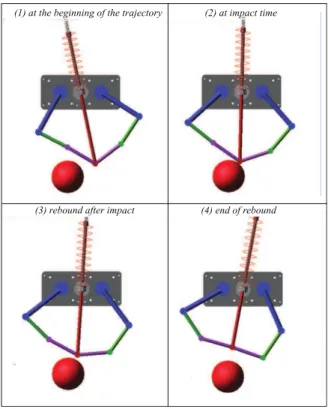
smaller than with the rigid robot: indeed, it can be observed that in the case of the collaborative robot, right after an impact, there is a rebound of the collided link, rebound which is possible due to the underactuated nature of our robot (Fig. 6). This rebound is not possible with the rigid five-bar mechanism, which thus transmits more energy to the head during the impact.
It should be also noted that, for the collaborative robot, the lower impact force and HIC value appear when contacting
near the passive revolute joint at O13. Indeed, a small force
TABLE II
IMPACT BETWEEN THE COLLABORATIVE ROBOT AND THE HEAD
Case Impact Head Peak HIC Duration Velocity Velocity Force
(m/s) (m/s) (N) (ms) 1 0.73 0.14 142 ≈ 0 10 2 1.05 0.10 162 ≈ 0 7 3 0.91 0.32 295 ≈ 0 13 4 1.20 0.45 530 4 9 TABLE III
IMPACT BETWEEN THE RIGID FIVE-BAR MECHANISM AND THE HEAD
Case Impact Head Peak HIC Duration Velocity Velocity Force
(m/s) (m/s) (N) (ms)
1 0.08 0.45 72 ≈ 0 66
2 0.70 1.12 648 7 18
3 0.73 1.61 861 15 20
4 1.50 2.86 2280 153 14
links as shown in Section II-C.2. This allows better energy dissipation during an impact.
D. Influence of the spring stiffness and of the robot speed In this Section, we analyze the effects for the collaborative robot of a change (a) in the spring stiffness and (b) in the duration of the reference trajectory, when impacting at the end-effector. The evolution of the HIC and of the peak impact force are provided in Fig. 7. It appears that worst case scenario does not happen when the robot is moving faster, but that there is a maximal robot speed for which the HIC and peak force are maximal and start to decrease. This is due to a combination of several factors:
• for lower speed trajectories, the links between O22, O23
and P are almost aligned at any time before the contact, thanks to the compression force exerted by the spring. These links thus behave as a single rigid body which does not reconfigure that much with the impact,
• for higher speed trajectories, the links between O22,
O23 and P are not aligned anymore before the contact
because inertia effects get larger. The configuration of these links authorizes a larger reconfiguration of the robot after the impact, thus decreasing the transmitted energy.
These phenomena, which explain the decrease of HIC and impact force at higher robot speeds, are illustrated in the video attached to the paper.
V. CONCLUSIONS AND FUTURE WORKS
In this paper, we introduced an intrinsically safe parallel manipulator for fast pick-and-place operations, called R-Min. R-Min has been designed so that the risk of injury during a collision with a human operator is reduced, while maintaining high speed and acceleration capacities. The proposed architecture is based on an underactuated parallel
(1) at the beginning of the trajectory (2) at impact time
(3) rebound after impact (4) end of rebound
Fig. 6. Illustration of an impact at the end-effector.
0.2 0.3 0.4 0.5 0.6 0.7 0.8 0.9 1 0 40 80 120 Trajectory duration (s) HIC 0 1 2 Pe ak impa ct force (kN) HIC (k=300 N/m) HIC (k=150 N/m) Force (k=80 N/m) Force (k= 150 N/m) Force (k=300 N/m) HIC (k=80 N/m)
Fig. 7. Evolution of the HIC and of the peak impact force as a function of the spring stiffness k and the trajectory duration.
kinematic chain constrained by a mechanical preload system mounted between the base and the end-effector. The robot is thus able to passively self-reconfigure during a collision.
A prototype of this new collaborative parallel robot was designed and its equilibrium configurations were studied under several types of loadings, as well as its dynamics. We analyzed the impact force and the HIC occurring during a collision between our prototype and the head of an operator and compared these results with those that would have been obtained with a rigid five-bar mechanism. Simulation results of impact during a standard pick-and-place trajectory showed that R-Min is intrinsically much safer than a regular rigid five-bar mechanism.
Our future works will concern the experimental validation of our simulation results, and the decrease of tracking errors by optimizing the design and developing proper control approaches. We also plan to extend the proposed concept to the design of collaborative parallel robots with more degrees of freedom.
REFERENCES
[1] N. Mansfeld, M. Hamad, M. Becker, A. G. Marin, and S. Haddadin, “Safety map: A unified representation for biomechanics impact data and robot instantaneous dynamic properties,” IEEE Robotics and Automation Letters, vol. 3, no. 3, pp. 1880–1887, 2018.
[2] J. Versace, “A review of the severity index,” SAE Technical Paper, Tech. Rep., 1971.
[3] D. Gao and C. W. Wampler, “Head injury criterion,” IEEE robotics & automation magazine, vol. 16, no. 4, pp. 71–74, 2009.
[4] M. Zinn, B. Roth, O. Khatib, and J. K. Salisbury, “A new actuation approach for human friendly robot design,” The international journal of robotics research, vol. 23, no. 4-5, pp. 379–398, 2004.
[5] A. Bicchi and G. Tonietti, “Fast and ”soft-arm” tactics [robot arm design],” IEEE Robotics & Automation Magazine, vol. 11, no. 2, pp. 22–33, 2004.
[6] G. Tonietti, R. Schiavi, and A. Bicchi, “Design and Control of a Variable Stiffness Actuator for Safe and Fast Physical Human/Robot Interaction,” in Proceedings of the 2005 IEEE International Confer-ence on Robotics and Automation, no. April. IEEE, pp. 526–531. [7] J. J. Park, S. Haddadin, J. B. Song, and A. Albu-Sch¨affer,
“De-signing optimally safe robot surface properties for minimizing the stress characteristics of Human-Robot collisions,” Proceedings - IEEE International Conference on Robotics and Automation, pp. 5413–5420, 2011.
[8] Technical Specification ISO/TS15066 : Robots and robotic devices — Collaborative robots, ISO Std. ISO/TS15 066, february 2016. [9] A. Muttray, B. Holz, M. Mainz, V. Bautz, and M. Umbreit,
“Bestimmung von druckschmerzschwellen an der mensch-maschine-schnittstelle–aktueller stand der forschung,” Tag der Arbeitssicherheit in Fellbach vom, vol. 13, no. 14.3, 2013.
[10] G. Hirzinger, N. Sporer, A. Albu-Schaffer, M. Hahnle, R. Krenn, A. Pascucci, and M. Schedl, “DLR’s torque-controlled light weight robot iii-are we reaching the technological limits now?” in Proceedings 2002 IEEE International Conference on Robotics and Automation (Cat. No. 02CH37292), vol. 2. IEEE, 2002, pp. 1710–1716. [11] Y. J. Kim, “Anthropomorphic low-inertia high-stiffness manipulator
for high-speed safe interaction,” IEEE Transactions on Robotics, vol. 33, no. 6, pp. 1358–1374, 2017.
[12] G. A. Pratt and M. M. Williamson, “Series elastic actuators,” in Proceedings 1995 IEEE/RSJ International Conference on Intelligent Robots and Systems. Human Robot Interaction and Cooperative Robots, vol. 1. IEEE, 1995, pp. 399–406.
[13] S.-S. Yoon, S. Kang, S.-k. Yun, S.-J. Kim, Y.-H. Kim, and M. Kim, “Safe arm design with mr-based passive compliant joints and visco—elastic covering for service robot applications,” Journal of mechanical science and technology, vol. 19, no. 10, pp. 1835–1845, 2005.
[14] O. Eiberger, S. Haddadin, M. Weis, A. Albu-Sch¨affer, and G. Hirzinger, “On joint design with intrinsic variable compliance: Derivation of the DLR QA-joint,” in 2010 IEEE International Con-ference on Robotics and Automation. IEEE, 2010, pp. 1687–1694. [15] S. Wolf, O. Eiberger, and G. Hirzinger, “The DLR FSJ: Energy
based design of a variable stiffness joint,” in 2011 IEEE International Conference on Robotics and Automation. IEEE, 2011, pp. 5082–5089. [16] J.-J. Park, B.-S. Kim, J.-B. Song, and H.-S. Kim, “Safe link mechanism based on nonlinear stiffness for collision safety,” Mechanism and Machine Theory, vol. 43, no. 10, pp. 1332–1348, 2008.
[17] N. Lauzier and C. Gosselin, “Performance indices for collaborative serial robots with optimally adjusted series clutch actuators,” Journal of Mechanisms and Robotics, vol. 4, no. 2, p. 021002, 2012. [18] J. L´opez-Mart´ınez, J. L. Blanco-Claraco, D. Garc´ıa-Vallejo, and
A. Gim´enez-Fern´andez, “Design and analysis of a flexible linkage for robot safe operation in collaborative scenarios,” Mechanism and Machine Theory, vol. 92, pp. 1–16, 2015.
[19] S. Seriani, P. Gallina, L. Scalera, and V. Lughi, “Development of n-dof preloaded structures for impact mitigation in cobots,” Journal of Mechanisms and Robotics, vol. 10, no. 5, p. 051009, 2018. [20] N. Lauzier and C. Gosselin, “3-dof cartesian force limiting device
based on the delta architecture for safe physical human-robot in-teraction,” in 2010 IEEE International Conference on Robotics and Automation. IEEE, 2010, pp. 3420–3425.
[21] J.-P. Merlet, Parallel robots. Springer Science & Business Media, 2006, vol. 128.
[22] V. Nabat, O. Company, S. Krut, M. D. L. O. Rodriguez, and F. Pierrot, “Par4: Very High Speed Parallel Robot for Pick and Place.”
[23] S. Grange, F. Conti, P. Rouiller, P. Helmer, and C. Baur, “The delta haptic device,” Tech. Rep., 2001.
[24] S. Zabihifar and A. Yuschenko, “Hybrid force/position control of a collaborative parallel robot using adaptive neural network,” in Inter-national Conference on Interactive Collaborative Robotics. Springer, 2018, pp. 280–290.
[25] F. Campa, M. Diez, D. Diaz-Caneja, and O. Altuzarra, “A 2 dof con-tinuum parallel robot for pick & place collaborative tasks,” in IFToMM World Congress on Mechanism and Machine Science. Springer, 2019, pp. 1979–1988.
[26] L. Campos, F. Bourbonnais, I. A. Bonev, and P. Bigras, “Development of a five-bar parallel robot with large workspace,” in ASME 2010 In-ternational Design Engineering Technical Conferences and Computers and Information in Engineering Conference. American Society of Mechanical Engineers Digital Collection, 2011, pp. 917–922. [27] L. Birglen, T. Lalibert´e, and C. M. Gosselin, Underactuated robotic
hands. Springer, 2007, vol. 40.
[28] R. Balderas Hill, S. Briot, A. Chriette, and P. Martinet, “Increasing energy efficiency of high-speed parallel robots by using variable stiffness springs and optimal motion generation,” in ASME 2018 Inter-national Design Engineering Technical Conferences and Computers and Information in Engineering Conference. American Society of Mechanical Engineers Digital Collection, 2018.
[29] L. Kaci, S. Briot, C. Boudaud, and P. Martinet, “Robecolo: Optimal design of a wooden five-bar mechanism,” in ASME 2018 International Design Engineering Technical Conferences and Computers and Infor-mation in Engineering Conference. American Society of Mechanical Engineers Digital Collection, 2018.
[30] J.-P. Merlet, “Solving the forward kinematics of a gough-type parallel manipulator with interval analysis,” The International Journal of Robotics Research, vol. 23, no. 3, pp. 221–235, 2004.
[31] S. Caro, D. Chablat, A. Goldsztejn, D. Ishii, and C. Jermann, “A Branch and Prune Algorithm for the Computation of Generalized Aspects of Parallel Robots,” Artificial Intelligence, vol. 221, pp. 34– 50, 2014.
[32] L. Jaulin, M. Kieffer, O. Didrit, and E. Walter, Applied interval analysis: with examples in parameter and state estimation, robust control and robotics. Springer Verlag, 2001.
[33] S. Briot, W. Khalil et al., “Dynamics of parallel robots,” From rigid bodies to flexible elements. Springer, 2015.
[34] C. Gosselin and J. Angeles, “Singularity analysis of closed-loop kinematic chains,” IEEE transactions on robotics and automation, vol. 6, no. 3, pp. 281–290, 1990.
[35] C. Germain, S. Caro, S. Briot, and P. Wenger, “Optimal design of the irsbot-2 based on an optimized test trajectory,” in ASME 2013 International Design Engineering Technical Conferences and Computers and Information in Engineering Conference. American Society of Mechanical Engineers Digital Collection, 2014.
[36] M. Idrees, S. Ullah, and S. Muhammad, “Sliding mode control design for stabilization of underactuated mechanical systems,” Advances in Mechanical Engineering, vol. 11, no. 5, pp. 1–10, 2019.
[37] J.-F. Gauthier, J. Angeles, and S. Nokleby, “Optimization of a test trajectory for scara systems,” in Advances in Robot Kinematics: Analysis and Design. Springer, 2008, pp. 225–234.
[38] M. Machado, P. Moreira, P. Flores, and H. M. Lankarani, “Compliant contact force models in multibody dynamics: Evolution of the hertz contact theory,” Mechanism and Machine Theory, vol. 53, pp. 99–121, 2012.