HAL Id: hal-02289335
https://hal.archives-ouvertes.fr/hal-02289335
Submitted on 16 Sep 2019
HAL is a multi-disciplinary open access
archive for the deposit and dissemination of
sci-entific research documents, whether they are
pub-lished or not. The documents may come from
teaching and research institutions in France or
abroad, or from public or private research centers.
L’archive ouverte pluridisciplinaire HAL, est
destinée au dépôt et à la diffusion de documents
scientifiques de niveau recherche, publiés ou non,
émanant des établissements d’enseignement et de
recherche français ou étrangers, des laboratoires
publics ou privés.
Identification of spindle dynamics by receptance
coupling for non-contact excitation system
Orkun Özşahin, Mathieu Ritou, Erhan Budak, Clément Rabréau, Sébastien
Le Loch
To cite this version:
Orkun Özşahin, Mathieu Ritou, Erhan Budak, Clément Rabréau, Sébastien Le Loch.
Identifica-tion of spindle dynamics by receptance coupling for non-contact excitaIdentifica-tion system. Procedia CIRP,
ELSEVIER, 2019, 17th CIRP Conference on Modelling of Machining Operations, Sheffield, United
Kingdom, 13-14 June 2019, 82, pp.273-278. �10.1016/j.procir.2019.04.038�. �hal-02289335�
ScienceDirect
Available online at www.sciencedirect.com
Available online at www.sciencedirect.com
ScienceDirect
Procedia CIRP 00 (2017) 000–000
www.elsevier.com/locate/procedia
2212-8271 © 2017 The Authors. Published by Elsevier B.V.
Peer-review under responsibility of the scientific committee of the 28th CIRP Design Conference 2018.
28th CIRP Design Conference, May 2018, Nantes, France
A new methodology to analyze the functional and physical architecture of
existing products for an assembly oriented product family identification
Paul Stief *, Jean-Yves Dantan, Alain Etienne, Ali Siadat
École Nationale Supérieure d’Arts et Métiers, Arts et Métiers ParisTech, LCFC EA 4495, 4 Rue Augustin Fresnel, Metz 57078, France
* Corresponding author. Tel.: +33 3 87 37 54 30; E-mail address: [email protected]
Abstract
In today’s business environment, the trend towards more product variety and customization is unbroken. Due to this development, the need of agile and reconfigurable production systems emerged to cope with various products and product families. To design and optimize production systems as well as to choose the optimal product matches, product analysis methods are needed. Indeed, most of the known methods aim to analyze a product or one product family on the physical level. Different product families, however, may differ largely in terms of the number and nature of components. This fact impedes an efficient comparison and choice of appropriate product family combinations for the production system. A new methodology is proposed to analyze existing products in view of their functional and physical architecture. The aim is to cluster these products in new assembly oriented product families for the optimization of existing assembly lines and the creation of future reconfigurable assembly systems. Based on Datum Flow Chain, the physical structure of the products is analyzed. Functional subassemblies are identified, and a functional analysis is performed. Moreover, a hybrid functional and physical architecture graph (HyFPAG) is the output which depicts the similarity between product families by providing design support to both, production system planners and product designers. An illustrative example of a nail-clipper is used to explain the proposed methodology. An industrial case study on two product families of steering columns of thyssenkrupp Presta France is then carried out to give a first industrial evaluation of the proposed approach.
© 2017 The Authors. Published by Elsevier B.V.
Peer-review under responsibility of the scientific committee of the 28th CIRP Design Conference 2018.
Keywords: Assembly; Design method; Family identification
1. Introduction
Due to the fast development in the domain of communication and an ongoing trend of digitization and digitalization, manufacturing enterprises are facing important challenges in today’s market environments: a continuing tendency towards reduction of product development times and shortened product lifecycles. In addition, there is an increasing demand of customization, being at the same time in a global competition with competitors all over the world. This trend, which is inducing the development from macro to micro markets, results in diminished lot sizes due to augmenting product varieties (high-volume to low-volume production) [1]. To cope with this augmenting variety as well as to be able to identify possible optimization potentials in the existing production system, it is important to have a precise knowledge
of the product range and characteristics manufactured and/or assembled in this system. In this context, the main challenge in modelling and analysis is now not only to cope with single products, a limited product range or existing product families, but also to be able to analyze and to compare products to define new product families. It can be observed that classical existing product families are regrouped in function of clients or features. However, assembly oriented product families are hardly to find.
On the product family level, products differ mainly in two main characteristics: (i) the number of components and (ii) the type of components (e.g. mechanical, electrical, electronical).
Classical methodologies considering mainly single products or solitary, already existing product families analyze the product structure on a physical level (components level) which causes difficulties regarding an efficient definition and comparison of different product families. Addressing this
Procedia CIRP 82 (2019) 273–278
2212-8271 © 2019 The Authors. Published by Elsevier B.V.
Peer-review under responsibility of the scientific committee of The 17th CIRP Conference on Modelling of Machining Operations 10.1016/j.procir.2019.04.038
© 2019 The Authors. Published by Elsevier B.V.
Peer-review under responsibility of the scientific committee of The 17th CIRP Conference on Modelling of Machining Operations
ScienceDirect
Procedia CIRP 00 (2019) 000–000
www.elsevier.com/locate/procedia
2212-8271 © 2019 The Authors. Published by Elsevier B.V.
Peer-review under responsibility of the scientific committee of The 17th CIRP Conference on Modelling of Machining Operations, in the person of the Conference Chair Dr Erdem Ozturk and Co-chairs Dr Tom Mcleay and Dr Rachid Msaoubi.
17th CIRP Conference on Modelling of Machining Operations
Identification of spindle dynamics by receptance coupling
for non-contact excitation system
Orkun Özşahin*
a, Mathieu Ritou
b, Erhan Budak
c,
Clément Rabréau
b, Sébastien Le Loch
ba Middle East Technical University, Ankara, 06800, Turkey
b LS2N (Laboratory of Digital Sciences of Nantes, UMR CNRS 6004), University of Nantes, 44000 Nantes, France c Manufacturing Research Laboratory, Sabanci University, Tuzla, İstanbul, 81474, Turkey
* Corresponding author. Tel.: +90 312 210 2568, E-mail address: [email protected]
Abstract
The identification of spindle dynamics plays a crucial role in accurate prediction of the stability diagrams for high speed machining operations. In this study, variations of the mode shapes of the tool-spindle assembly at high spindle speeds are examined using numerical models and hypotheses are formulated. An identification method of spindle dynamics is proposed, dedicated to non-contact excitation system; from which only cross FRF can be obtained (instead of tool tip FRF classically). Then, spindle dynamics is calculated using inverse Receptance Coupling (RC) method. Proposed method enables the identification of the speed dependent spindle dynamics in the full frequency range. The approach has been verified with the Finite Element Model (FEM) of a spindle-bearing assembly. The prediction by RC of the dynamics of another tool has been successfully compared to the FEM simulation.
© 2019 The Authors. Published by Elsevier B.V.
Peer-review under responsibility of the scientific committee of The 17th CIRP Conference on Modelling of Machining Operations, in the person of the Conference Chair Dr Erdem Ozturk and Co-chairs Dr Tom Mcleay and Dr Rachid Msaoubi.
Keywords: Spindle dynamics, receptance coupling, non-contact excitation.
1. Introduction
Chatter is an important problem in machining operations and can be avoided using stability diagrams [1,2]. In order to determine stability diagrams, tool point FRF should be determined and generally, tool point FRF is obtained for the idle state of the machine. However, under operational conditions dynamics of the spindle-bearing assembly changes due to the centrifugal forces, gyroscopic moments and thermal expansions. Thus, tool point FRFs obtained for the idle state of the machine lead to inaccurate stability predictions.
In order to predict the tool point FRF under operational conditions, there have been both experimental and modeling approaches. Altintas and Cao [3,4] modeled the
spindle-bearing assembly including tool, housing, and machine-tool structure dynamics. They used speed dependent bearing model presented by Harris [5]. Advanced models of the preloaded bearing system are also proposed by Rabreau et al. [6]. In addition, Movahhedy and Mosaddegh [7] included the effects of gyroscopic effect in the spindle model. Similarly, Ozsahin et al [8] modeled spindle-holder-tool assembly using analytical solution of Timoshenko beams including gyroscopic moments and centrifugal forces. Modeling approaches showed that main source of deviations is the dynamic changes in the bearings with spindle speed. This is an expected result since bearing stiffness values decrease with increasing speed [4,6,9,10] and bearing dynamics mainly effect the spindle modes of the assembly [11]. In addition to dynamic models, there are also
Available online at www.sciencedirect.com
ScienceDirect
Procedia CIRP 00 (2019) 000–000
www.elsevier.com/locate/procedia
2212-8271 © 2019 The Authors. Published by Elsevier B.V.
Peer-review under responsibility of the scientific committee of The 17th CIRP Conference on Modelling of Machining Operations, in the person of the Conference Chair Dr Erdem Ozturk and Co-chairs Dr Tom Mcleay and Dr Rachid Msaoubi.
17th CIRP Conference on Modelling of Machining Operations
Identification of spindle dynamics by receptance coupling
for non-contact excitation system
Orkun Özşahin*
a, Mathieu Ritou
b, Erhan Budak
c,
Clément Rabréau
b, Sébastien Le Loch
ba Middle East Technical University, Ankara, 06800, Turkey
b LS2N (Laboratory of Digital Sciences of Nantes, UMR CNRS 6004), University of Nantes, 44000 Nantes, France c Manufacturing Research Laboratory, Sabanci University, Tuzla, İstanbul, 81474, Turkey
* Corresponding author. Tel.: +90 312 210 2568, E-mail address: [email protected]
Abstract
The identification of spindle dynamics plays a crucial role in accurate prediction of the stability diagrams for high speed machining operations. In this study, variations of the mode shapes of the tool-spindle assembly at high spindle speeds are examined using numerical models and hypotheses are formulated. An identification method of spindle dynamics is proposed, dedicated to non-contact excitation system; from which only cross FRF can be obtained (instead of tool tip FRF classically). Then, spindle dynamics is calculated using inverse Receptance Coupling (RC) method. Proposed method enables the identification of the speed dependent spindle dynamics in the full frequency range. The approach has been verified with the Finite Element Model (FEM) of a spindle-bearing assembly. The prediction by RC of the dynamics of another tool has been successfully compared to the FEM simulation.
© 2019 The Authors. Published by Elsevier B.V.
Peer-review under responsibility of the scientific committee of The 17th CIRP Conference on Modelling of Machining Operations, in the person of the Conference Chair Dr Erdem Ozturk and Co-chairs Dr Tom Mcleay and Dr Rachid Msaoubi.
Keywords: Spindle dynamics, receptance coupling, non-contact excitation.
1. Introduction
Chatter is an important problem in machining operations and can be avoided using stability diagrams [1,2]. In order to determine stability diagrams, tool point FRF should be determined and generally, tool point FRF is obtained for the idle state of the machine. However, under operational conditions dynamics of the spindle-bearing assembly changes due to the centrifugal forces, gyroscopic moments and thermal expansions. Thus, tool point FRFs obtained for the idle state of the machine lead to inaccurate stability predictions.
In order to predict the tool point FRF under operational conditions, there have been both experimental and modeling approaches. Altintas and Cao [3,4] modeled the
spindle-bearing assembly including tool, housing, and machine-tool structure dynamics. They used speed dependent bearing model presented by Harris [5]. Advanced models of the preloaded bearing system are also proposed by Rabreau et al. [6]. In addition, Movahhedy and Mosaddegh [7] included the effects of gyroscopic effect in the spindle model. Similarly, Ozsahin et al [8] modeled spindle-holder-tool assembly using analytical solution of Timoshenko beams including gyroscopic moments and centrifugal forces. Modeling approaches showed that main source of deviations is the dynamic changes in the bearings with spindle speed. This is an expected result since bearing stiffness values decrease with increasing speed [4,6,9,10] and bearing dynamics mainly effect the spindle modes of the assembly [11]. In addition to dynamic models, there are also
274 Orkun Özşahin et al. / Procedia CIRP 82 (2019) 273–278
Author name / Procedia CIRP 00 (2019) 000–000 3
𝐻𝐻15= ∑ 𝜔𝜔 𝜙𝜙𝑟𝑟1𝜙𝜙𝑟𝑟5 𝑟𝑟2− 𝜔𝜔2+ i2ξ𝑟𝑟ω𝜔𝜔𝑟𝑟 (3) 𝑁𝑁 𝑟𝑟=1 𝐻𝐻55= ∑ 𝜔𝜔𝑟𝑟2− 𝜔𝜔𝜙𝜙𝑟𝑟25+ i2ξ𝑟𝑟ω𝜔𝜔𝑟𝑟 𝜙𝜙𝑟𝑟5 𝑁𝑁 𝑟𝑟=1 (4) Unknown 𝜔𝜔𝑟𝑟 and ξ𝑟𝑟 can be obtained using non-contact excitation measurements since these modal parameters will be same for all FRFs at different locations along the tool axis. On the contrary, mode shapes cannot be directly obtained from these measurements since non-contact measurements will only provide 𝐻𝐻23 and 𝐻𝐻43. At this point, one common approach might be the constant mode shape assumption where it is assumed that mode shapes will remain the same whatever the spindle speed. Based on that assumption, mode shapes can be identified using impact test on a stopped spindle and assumed as constant at all spindle speeds. However, FEM simulations showed that mode shapes change with spindle speed and this assumption is not valid. Variation of mode shapes with spindle speed is verified in Section 3.3.
In this study, due to the design of the dummy tool (Figure
2), it is proposed to assume as linear the mode shapes of the dummy tool, (in the frequency range of interest) as shown in Figure 1. This is a valid assumption since spindle modes will be dominant for the dummy tool case. Validity of this assumption is also verified using FEM results and these results are also presented in Section 3. Based on this assumption, values of each mode shape at each location can be obtained as follows: 𝜙𝜙𝑟𝑟3= 𝐶𝐶1, 𝜙𝜙𝑟𝑟2=𝐴𝐴23 𝑟𝑟 𝐶𝐶1, 𝜙𝜙𝑟𝑟 4=𝐴𝐴43𝑟𝑟 𝐶𝐶1 𝐶𝐶1= √𝐶𝐶2(𝐴𝐴𝑟𝑟23− 𝐴𝐴43𝑟𝑟 ) + 𝐴𝐴43𝑟𝑟 𝐶𝐶2=𝐿𝐿 𝐿𝐿34 34+ 𝐿𝐿32
where 𝐴𝐴32𝑟𝑟 and 𝐴𝐴34𝑟𝑟 are modal constants identified using measured 𝐻𝐻23 and 𝐻𝐻43. In addition, 𝐿𝐿34 is the distance between locations 3 and 4, 𝐿𝐿32 is the distance between locations 3 and 2. Similarly, 𝜙𝜙𝑟𝑟1=𝜙𝜙𝑟𝑟3+ (𝐶𝐶3− 1)𝜙𝜙𝑟𝑟4 𝐶𝐶3 𝜙𝜙𝑟𝑟5=𝐶𝐶4𝜙𝜙𝑟𝑟3− 𝜙𝜙𝑟𝑟4 𝐶𝐶4− 1 where 𝐶𝐶3=𝐿𝐿34+ 𝐿𝐿32𝐿𝐿34+ 𝐿𝐿12 𝐶𝐶4=𝐿𝐿45𝐿𝐿+ 𝐿𝐿3445
Finally, using predicted mass normalized mode shapes (𝜙𝜙𝑟𝑟1 𝑎𝑎𝑎𝑎𝑎𝑎 𝜙𝜙𝑟𝑟5 ) and identified modal parameters (𝜔𝜔𝑟𝑟 and ξ𝑟𝑟 )
point and cross FRFs at locations 1 and 5 can be obtained as using Equations 2-4. Then spindle dynamics can be identified using the method proposed by Namazi and Altintas [21]. In this study FRFs of the free-free dummy tool is obtained using analytical solution of Timoshenko beam equations and receptance coupling method [25]. Then spindle dynamics is identified using predicted spindle-tool assembly FRFs, analytical calculated tool FRFs and inverse receptance coupling method.
3. Verification
3.1. Presentation of FEM model
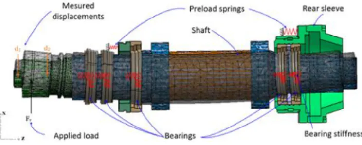
A Finite Element Model (FEM) of an industrial spindle is used in order to evaluate the identification method proposed in this paper. The spindle is a Fischer MFW 2310, 70 kW, 24 000 RPM; that consists of 5 hybrid angular contact ball bearings (three SKF VEX70 at the front and two VEX60 at the rear) in back-to-back arrangements with two spring preload systems. The main components of the numerical model are presented in Figure 2. The behavior of the angular contact ball
bearings is taken into account through a 5DoF stiffness model that depends on spindle speed. The dynamic effects in the bearings are taken into account. Stiffness values are obtained by update of an analytical model of the preloaded spindle axial behavior [6]. The shaft and the dummy-tool are modeled by 3D finite-elements. The HSK interface is considered as rigid. Catia Generative Structural Analysis was used for the simulations of spindle dynamics.
Figure 2. Spindle model for the verifications.
3.2. Identification
In order to verify the proposed method, spindle FEM given in Section 3.1 is used. In FEM, same dummy tool (Figure 1) which is used in non-contact excitation measurements is clamped to spindle-bearing assembly. Then in order to simulate the non-contact measurements, point and cross FRFs ( 𝐻𝐻23 and 𝐻𝐻43) are obtained through FEM at various spindle speeds. The simulated cross FRFs H23 are given in Figure 3 at several
speeds. Also the natural frequencies identified on the simulated cross FRF are given in Table 1.
As seen from Figure 3 and Table 1, FRF of the spindle-tool assembly changes due to rotational effects and natural frequencies of the system decrease. This is an expected result because, due to gyroscopic moments and centrifugal forces bearing stiffness values decrease with increasing spindle rotational speed [5,6]. Also as expressed by Erturk et al. [25], front and rear bearings mainly effects the spindle and holder
2 Author name / Procedia CIRP 00 (2019) 000–000
thermo-mechanical models, which include both dynamic and thermal effects [12-14].
Main limitation of the developed models is the difficulties in accurate modeling and in correct updating of detailed spindle-bearing assembly with various contacts. In addition, these models require the detailed geometry of the spindle assembly which is often not available. Therefore, modeling approaches provide an efficient tool for the design and optimization of the spindle-bearing assembly but they lack the accurate prediction of the tool point FRFs.
In addition, there are various experimental approaches for the identification of in-process tool point FRFs such as; operational modal analysis [15], non-contact excitation systems [16-18] and inverse stability identification [19,20].
Main limitation of the experimental approaches is the necessity of the measurements for each holder-tool combinations which is often not possible for machine shop applications. To alter this limitation, Namazi and Altintas [21] proposed an identification method which can be easily applied to idle conditions. Later Grossi et al. [22,23] identified spindle dynamics based on tool point FRFs obtained using inverse stability method. Also, in a recent study, Postel et al. [24] identified speed dependent spindle dynamics using the tool point FRF obtained through inverse stability method.
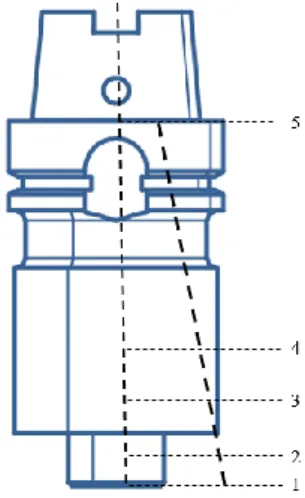
Inverse stability method provides an efficient and fast method for the identification of in process tool point FRF. In addition, tool point FRF obtained using this approach includes the all possible effects of real machining conditions. However, this approach provides only the deviation of the dominant mode that causes chatter and does not provide the tool point FRF in a wider frequency range. On the other hand, non-contact excitation systems provide the experimental tool-spindle FRFs on large frequency range for any spindle speed, which consequently include all the dynamic effects. A dummy tool with a ferromagnetic core is necessary (e.g. at the height of section 3 in Fig 1). Thus the approach cannot be applied with a real cutting tool. In addition, non-contact excitation system cannot provide the tool tip FRF. Indeed, displacement sensor generally cannot be integrated at the height of the electromagnet, but only at other heights (e.g. sections 2 or 4 in Fig 1). Thus, only cross FRF of dummy tool-spindle can be obtained. Consequently, in order to be able to predict the tool tip FRF a given cutting tool from the spindle dynamics assessed with a non-contact excitation device, a new identification method is required and RC approach seems suitable.
In this study, spindle identification procedure is presented for the non-contact excitation measurements. First, point and cross FRF of the spindle-tool assembly is predicted using the cross FRFs. Then speed dependent spindle dynamics is identified. Proposed method is verified through numerical simulations with a FEM of a spindle-bearing-tool assembly.
2. RC identification with linear interpolation
Spindle dynamics can be identified using the method proposed by Namazi and Altintas [21] where analytically obtained free-free holder-tool assembly dynamics is subtracted from the experimentally measured spindle-holder-tool assembly dynamics. In this approach, to identify the spindle
dynamics, point and cross FRFs of the spindle-holder-tool assembly are required and these FRFs can be obtained using impact testing on a stopped spindle. Indeed, impact tests cannot be applied while spindle is rotating at high speeds due to inaccuracy and safety reasons. At this point, non-contact excitation system can be used to measure the FRFs of the rotating spindle-holder-tool assembly. Main limitation of the non-contact excitation measurements is that FRF at the tip cannot be measured using non-contact excitation system. Instead, cross FRF 𝐻𝐻23 and 𝐻𝐻43 (Figure 1) can be obtained experimentally using non-contact excitation systems [18]. However, for the spindle identification, FRFs at tool tip 𝐻𝐻11, spindle flange 𝐻𝐻55 and across 𝐻𝐻15 are required (Figure 1). In these FRF expressions, first subscript m represents the point of response measurement and second subscript n represents the point of excitation force.
Figure 1. FRF measurement locations and assumed mode shape (black dash line) for the dummy tool.
FRF at any location can be represented as follows: 𝐻𝐻𝑚𝑚𝑚𝑚 = ∑ 𝐴𝐴𝑚𝑚𝑚𝑚 𝑟𝑟 𝜔𝜔𝑟𝑟2− 𝜔𝜔2+ i2ξω𝜔𝜔𝑟𝑟 𝑁𝑁 𝑟𝑟=1 = ∑ 𝜔𝜔𝑟𝑟2− 𝜔𝜔𝜙𝜙2𝑟𝑟𝑚𝑚+ i2ξ𝑟𝑟ω𝜔𝜔𝑟𝑟 𝜙𝜙𝑟𝑟𝑚𝑚 𝑁𝑁 𝑟𝑟=1 (1) where 𝜔𝜔𝑟𝑟 is the natural frequency of the rth mode, ξ𝑟𝑟 is the
damping ratio of the rth mode, 𝐴𝐴𝑚𝑚𝑚𝑚𝑟𝑟 is the modal constant, ω is the excitation frequency and 𝜙𝜙𝑟𝑟𝑚𝑚 is the mass normalized rth
mode shape at location n. Also note that for proportional damping, modal constant will be real and can be expressed as the multiplication of the mass normalized mode shapes as shown in Equation 1.
In order to determine unknown FRFs at location 1 and 5 (𝐻𝐻11, 𝐻𝐻15 and 𝐻𝐻55), 𝜔𝜔𝑟𝑟, ξ𝑟𝑟 and mass normalized mode shapes at location 1 and 5 (𝜙𝜙𝑟𝑟1, 𝜙𝜙𝑟𝑟5) are required.
𝐻𝐻11= ∑ 𝜙𝜙𝑟𝑟 1𝜙𝜙𝑟𝑟1 𝜔𝜔𝑟𝑟2− 𝜔𝜔2+ i2ξ𝑟𝑟ω𝜔𝜔𝑟𝑟 (2) 𝑁𝑁 𝑟𝑟=1
𝐻𝐻15= ∑ 𝜔𝜔 𝜙𝜙𝑟𝑟1𝜙𝜙𝑟𝑟5 𝑟𝑟2− 𝜔𝜔2+ i2ξ𝑟𝑟ω𝜔𝜔𝑟𝑟 (3) 𝑁𝑁 𝑟𝑟=1 𝐻𝐻55= ∑ 𝜔𝜔𝑟𝑟2− 𝜔𝜔𝜙𝜙𝑟𝑟25+ i2ξ𝑟𝑟ω𝜔𝜔𝑟𝑟 𝜙𝜙𝑟𝑟5 𝑁𝑁 𝑟𝑟=1 (4) Unknown 𝜔𝜔𝑟𝑟 and ξ𝑟𝑟 can be obtained using non-contact excitation measurements since these modal parameters will be same for all FRFs at different locations along the tool axis. On the contrary, mode shapes cannot be directly obtained from these measurements since non-contact measurements will only provide 𝐻𝐻23 and 𝐻𝐻43. At this point, one common approach might be the constant mode shape assumption where it is assumed that mode shapes will remain the same whatever the spindle speed. Based on that assumption, mode shapes can be identified using impact test on a stopped spindle and assumed as constant at all spindle speeds. However, FEM simulations showed that mode shapes change with spindle speed and this assumption is not valid. Variation of mode shapes with spindle speed is verified in Section 3.3.
In this study, due to the design of the dummy tool (Figure
2), it is proposed to assume as linear the mode shapes of the dummy tool, (in the frequency range of interest) as shown in Figure 1. This is a valid assumption since spindle modes will be dominant for the dummy tool case. Validity of this assumption is also verified using FEM results and these results are also presented in Section 3. Based on this assumption, values of each mode shape at each location can be obtained as follows: 𝜙𝜙𝑟𝑟3= 𝐶𝐶1, 𝜙𝜙𝑟𝑟2=𝐴𝐴23 𝑟𝑟 𝐶𝐶1, 𝜙𝜙𝑟𝑟 4=𝐴𝐴43𝑟𝑟 𝐶𝐶1 𝐶𝐶1= √𝐶𝐶2(𝐴𝐴𝑟𝑟23− 𝐴𝐴43𝑟𝑟 ) + 𝐴𝐴43𝑟𝑟 𝐶𝐶2=𝐿𝐿 𝐿𝐿34 34+ 𝐿𝐿32
where 𝐴𝐴32𝑟𝑟 and 𝐴𝐴34𝑟𝑟 are modal constants identified using measured 𝐻𝐻23 and 𝐻𝐻43. In addition, 𝐿𝐿34 is the distance between locations 3 and 4, 𝐿𝐿32 is the distance between locations 3 and 2. Similarly, 𝜙𝜙𝑟𝑟1=𝜙𝜙𝑟𝑟3+ (𝐶𝐶3− 1)𝜙𝜙𝑟𝑟4 𝐶𝐶3 𝜙𝜙𝑟𝑟5=𝐶𝐶4𝜙𝜙𝑟𝑟3− 𝜙𝜙𝑟𝑟4 𝐶𝐶4− 1 where 𝐶𝐶3=𝐿𝐿34+ 𝐿𝐿32𝐿𝐿34+ 𝐿𝐿12 𝐶𝐶4=𝐿𝐿45𝐿𝐿+ 𝐿𝐿3445
Finally, using predicted mass normalized mode shapes (𝜙𝜙𝑟𝑟1 𝑎𝑎𝑎𝑎𝑎𝑎 𝜙𝜙𝑟𝑟5 ) and identified modal parameters (𝜔𝜔𝑟𝑟 and ξ𝑟𝑟 )
point and cross FRFs at locations 1 and 5 can be obtained as using Equations 2-4. Then spindle dynamics can be identified using the method proposed by Namazi and Altintas [21]. In this study FRFs of the free-free dummy tool is obtained using analytical solution of Timoshenko beam equations and receptance coupling method [25]. Then spindle dynamics is identified using predicted spindle-tool assembly FRFs, analytical calculated tool FRFs and inverse receptance coupling method.
3. Verification
3.1. Presentation of FEM model
A Finite Element Model (FEM) of an industrial spindle is used in order to evaluate the identification method proposed in this paper. The spindle is a Fischer MFW 2310, 70 kW, 24 000 RPM; that consists of 5 hybrid angular contact ball bearings (three SKF VEX70 at the front and two VEX60 at the rear) in back-to-back arrangements with two spring preload systems. The main components of the numerical model are presented in Figure 2. The behavior of the angular contact ball
bearings is taken into account through a 5DoF stiffness model that depends on spindle speed. The dynamic effects in the bearings are taken into account. Stiffness values are obtained by update of an analytical model of the preloaded spindle axial behavior [6]. The shaft and the dummy-tool are modeled by 3D finite-elements. The HSK interface is considered as rigid. Catia Generative Structural Analysis was used for the simulations of spindle dynamics.
Figure 2. Spindle model for the verifications.
3.2. Identification
In order to verify the proposed method, spindle FEM given in Section 3.1 is used. In FEM, same dummy tool (Figure 1) which is used in non-contact excitation measurements is clamped to spindle-bearing assembly. Then in order to simulate the non-contact measurements, point and cross FRFs ( 𝐻𝐻23 and 𝐻𝐻43) are obtained through FEM at various spindle speeds. The simulated cross FRFs H23 are given in Figure 3 at several
speeds. Also the natural frequencies identified on the simulated cross FRF are given in Table 1.
As seen from Figure 3 and Table 1, FRF of the spindle-tool assembly changes due to rotational effects and natural frequencies of the system decrease. This is an expected result because, due to gyroscopic moments and centrifugal forces bearing stiffness values decrease with increasing spindle rotational speed [5,6]. Also as expressed by Erturk et al. [25], front and rear bearings mainly effects the spindle and holder thermo-mechanical models, which include both dynamic and
thermal effects [12-14].
Main limitation of the developed models is the difficulties in accurate modeling and in correct updating of detailed spindle-bearing assembly with various contacts. In addition, these models require the detailed geometry of the spindle assembly which is often not available. Therefore, modeling approaches provide an efficient tool for the design and optimization of the spindle-bearing assembly but they lack the accurate prediction of the tool point FRFs.
In addition, there are various experimental approaches for the identification of in-process tool point FRFs such as; operational modal analysis [15], non-contact excitation systems [16-18] and inverse stability identification [19,20].
Main limitation of the experimental approaches is the necessity of the measurements for each holder-tool combinations which is often not possible for machine shop applications. To alter this limitation, Namazi and Altintas [21] proposed an identification method which can be easily applied to idle conditions. Later Grossi et al. [22,23] identified spindle dynamics based on tool point FRFs obtained using inverse stability method. Also, in a recent study, Postel et al. [24] identified speed dependent spindle dynamics using the tool point FRF obtained through inverse stability method.
Inverse stability method provides an efficient and fast method for the identification of in process tool point FRF. In addition, tool point FRF obtained using this approach includes the all possible effects of real machining conditions. However, this approach provides only the deviation of the dominant mode that causes chatter and does not provide the tool point FRF in a wider frequency range. On the other hand, non-contact excitation systems provide the experimental tool-spindle FRFs on large frequency range for any spindle speed, which consequently include all the dynamic effects. A dummy tool with a ferromagnetic core is necessary (e.g. at the height of section 3 in Fig 1). Thus the approach cannot be applied with a real cutting tool. In addition, non-contact excitation system cannot provide the tool tip FRF. Indeed, displacement sensor generally cannot be integrated at the height of the electromagnet, but only at other heights (e.g. sections 2 or 4 in Fig 1). Thus, only cross FRF of dummy tool-spindle can be obtained. Consequently, in order to be able to predict the tool tip FRF a given cutting tool from the spindle dynamics assessed with a non-contact excitation device, a new identification method is required and RC approach seems suitable.
In this study, spindle identification procedure is presented for the non-contact excitation measurements. First, point and cross FRF of the spindle-tool assembly is predicted using the cross FRFs. Then speed dependent spindle dynamics is identified. Proposed method is verified through numerical simulations with a FEM of a spindle-bearing-tool assembly.
2. RC identification with linear interpolation
Spindle dynamics can be identified using the method proposed by Namazi and Altintas [21] where analytically obtained free-free holder-tool assembly dynamics is subtracted from the experimentally measured spindle-holder-tool assembly dynamics. In this approach, to identify the spindle
dynamics, point and cross FRFs of the spindle-holder-tool assembly are required and these FRFs can be obtained using impact testing on a stopped spindle. Indeed, impact tests cannot be applied while spindle is rotating at high speeds due to inaccuracy and safety reasons. At this point, non-contact excitation system can be used to measure the FRFs of the rotating spindle-holder-tool assembly. Main limitation of the non-contact excitation measurements is that FRF at the tip cannot be measured using non-contact excitation system. Instead, cross FRF 𝐻𝐻23 and 𝐻𝐻43 (Figure 1) can be obtained experimentally using non-contact excitation systems [18]. However, for the spindle identification, FRFs at tool tip 𝐻𝐻11, spindle flange 𝐻𝐻55 and across 𝐻𝐻15 are required (Figure 1). In these FRF expressions, first subscript m represents the point of response measurement and second subscript n represents the point of excitation force.
Figure 1. FRF measurement locations and assumed mode shape (black dash line) for the dummy tool.
FRF at any location can be represented as follows: 𝐻𝐻𝑚𝑚𝑚𝑚 = ∑ 𝐴𝐴𝑚𝑚𝑚𝑚 𝑟𝑟 𝜔𝜔𝑟𝑟2− 𝜔𝜔2+ i2ξω𝜔𝜔𝑟𝑟 𝑁𝑁 𝑟𝑟=1 = ∑ 𝜔𝜔𝑟𝑟2− 𝜔𝜔𝜙𝜙2𝑟𝑟𝑚𝑚+ i2ξ𝑟𝑟ω𝜔𝜔𝑟𝑟 𝜙𝜙𝑟𝑟𝑚𝑚 𝑁𝑁 𝑟𝑟=1 (1) where 𝜔𝜔𝑟𝑟 is the natural frequency of the rth mode, ξ𝑟𝑟 is the
damping ratio of the rth mode, 𝐴𝐴𝑚𝑚𝑚𝑚𝑟𝑟 is the modal constant, ω is the excitation frequency and 𝜙𝜙𝑟𝑟𝑚𝑚 is the mass normalized rth
mode shape at location n. Also note that for proportional damping, modal constant will be real and can be expressed as the multiplication of the mass normalized mode shapes as shown in Equation 1.
In order to determine unknown FRFs at location 1 and 5 (𝐻𝐻11, 𝐻𝐻15 and 𝐻𝐻55), 𝜔𝜔𝑟𝑟, ξ𝑟𝑟 and mass normalized mode shapes at location 1 and 5 (𝜙𝜙𝑟𝑟1, 𝜙𝜙𝑟𝑟5) are required.
𝐻𝐻11= ∑ 𝜙𝜙𝑟𝑟 1𝜙𝜙𝑟𝑟1 𝜔𝜔𝑟𝑟2− 𝜔𝜔2+ i2ξ𝑟𝑟ω𝜔𝜔𝑟𝑟 (2) 𝑁𝑁 𝑟𝑟=1
276 Orkun Özşahin et al. / Procedia CIRP 82 (2019) 273–278
Author name / Procedia CIRP 00 (2019) 000–000 5
4. Results of Receptance Coupling
4.1. Spindle identification
After the prediction of point and cross FRFs of the spindle-tool assembly, dynamics of the dummy spindle-tool is subtracted from the dynamics of spindle-tool assembly using the method proposed by Namazi and Altintas [21]. Dynamics of dummy tool at free-free end condition is calculated using the analytical solution of Timoshenko beam and receptance coupling. Identified spindle dynamics 𝐻𝐻55𝑆𝑆 (at spindle flange without tool) at different spindle speeds are also given in Figure 6.
There is significant deviation in the spindle dynamics with the increasing spindle speed, which is mainly due to the decrease of bearing stiffness [3]. In addition, deviation in bearing stiffness values increases at high spindle speeds. As can be observed in Figure 6, there is a significant change between 24000rpm and 15000 rpm. Also note that, identified spindle dynamics given in Figure 6, includes the dynamics of spindle, tool portion inside the spindle and effects of the contact mechanism at the spindle-holder flange interface. Contrary to the dummy tool-spindle assembly for which the dominant mode is the font bearing mode (at 1309Hz, Figure 5), the dominant of the identified spindle (without tool) is the shaft bending mode (at 2500Hz).
Figure 6. Identified spindle 𝐻𝐻55𝑆𝑆 at various speeds.
4.2. Prediction for another tool
In order to verify the accuracy of the identified spindle dynamics, a different tool with a diameter of 32 mm and a length of 175 mm is clamped to the spindle. Then tool point FRF H11 is obtained by coupling the identified spindle
dynamics (𝐻𝐻55𝑆𝑆 ) with the calculated tool dynamics. Tool point and cross FRFs are obtained using FEM for the free-free boundary conditions and then coupled with the identified spindle dynamics using receptance coupling method. In addition, tool point FRF is also calculated using the full spindle-tool FEM. Obtained FRFs H11 are given in Figure 7 for
various spindle speeds. As shown in Figure 7, tool point FRF of an arbitrary tool can be accurately predicted using the proposed method. The dominant varies from 726 Hz to 688 Hz with speed. Difference between predicted natural frequency of the dominant mode and FEM is 0.69 %, 0.47 % and 0.50 % for the stopped spindle, 15.000 rpm and 24.000 rpm spindle speeds respectively. In addition, for the second mode (at 1042 Hz to 845 Hz), the eigenfrequency is well predicted but the amplitude
is overestimated. A possible reason is the assumption of linear mode shape that is less relevant for the second mode, as can be seen in Figure 5.
Figure 7. Comparison of tool tip FRF with a different tool, obtained by FEM and by the proposed RC method a) 0 rpm, b) 15000 rpm and c) 24000 rpm.
5. Conclusion
In this paper, a spindle identification method for measurement of non-contact excitation system is presented. In the proposed method, mode shapes of the spindle-tool assembly are considered as speed dependent and determined based on the assumption of linear mode shape of the dummy tool. Validity of this assumption is verified using FEM simulation of an industrial spindle. Based on the FEM results, it is shown that mode shapes changes under operational conditions and their values at the tool tip can be accurately predicted using the proposed method. In addition, spindle dynamics is identified using the proposed method. Then the identified spindle dynamics is coupled with a new tool. The estimation of tool point FRF for the new tool is also validated by the FEM.
a)
b)
c)
4 Author name / Procedia CIRP 00 (2019) 000–000
modes. Thus, decrease in the bearing stiffness values result in decrease in the natural frequency of the spindle dominant modes.
Figure 3. Variation of cross FRF (H21) of the spindle-dummy tool assembly
with various spindle speeds. Table 1 Natural frequencies identified from simulations [Hz]
Mode 0 rpm 15.000 rpm 20.000 rpm 24.000 rpm 1 960.4 873.3 769.5 781.7 2 1308.6 1228.8 914.9 996.4 3 1506.8 1360.9 1270.0 1277.8
3.3. Mode shape evolution with speed
In addition to variations in natural frequencies, modal constants at various spindle speeds are identified using modal analysis (Table 2). One important observation obtained from these simulations is that modal constants thus mode shapes are also effected by the spindle rotational speed. For instance as shown in Table 2, when spindle speed is increased from 0 rpm to 20.000 rpm, modal constant for the first mode 𝐴𝐴121 decreases to 58% of the idle state. Similarly, there is 27% decrease in modal constant for the second mode when spindle speed is increase from 0 rpm to 20.000 rpm. This is also an expected result, since bearing stiffness variations have different amount of effect on each mode due to the dynamics of the whole system [26].
Table 2 Identified modal constants 𝐴𝐴12𝑟𝑟
Mode 0 rpm 15.000 rpm 20.000 rpm 24.000 rpm H12
1 0.1427 0.1034 0.0593 0.0773 2 0.4725 0.4813 0.3377 0.3432 3 0.0077 0.0148 0.1282 0.1146
3.4. Validation of linearity hypothesis
As expressed in Section 2, it is assumed that the mode shape of the dummy tool is linear the dummy tool, Consequently, FRF at the tip H11 and spindle flange H55 (spindle-dummy tool
assembly) can be predicted using the mode shape assumption.
In order to check the accuracy of the method, cross FRF 𝐻𝐻23 and 𝐻𝐻43 are simulated using the FEM. Then mode shapes are evaluated at locations 1 and 5 using the proposed method. Finally, point and cross FRFs at locations 1 and 5 are calculated. Figure 4 compares the predicted (by RC) and the calculated (FEM) FRF at tool tip H11.
Figure 4. H11 for the spindle-dummy tool assembly obtained using FEM and
proposed RC method for stopped spindle.
As seen in Figure 4, using the proposed method, unknown point and cross FRFs can be accurately predicted.
In addition to the FRFs, mode shape functions at the tool tip is identified using both the proposed method and FEM. Results are given in Table 3 and as shown in Table 3, linear assumption provides accurate results for the modes in the frequency range of interest. Moreover, mode shapes are examined using FEM and obtained results are given in Figure 5. It illustrates that the first and second modes are mainly spindle modes. These modes show a linear variation in the dummy tool section of the assembly. These results also verify the linear mode shape assumption in the dummy tool section, in the frequency range of interest.
Figure 5 Dominant modes of the studied spindle
Table 3 Modal constants (𝐴𝐴11𝑟𝑟 ) at tool tip obtained using FEM and the proposed
RC method (for stopped spindle).
Location Mode FEM Predicted Error (%) 1 1 0.4268 0.4271 0.07
2 0.7670 0.7679 0.12
Shaft bending mode at 961Hz
4. Results of Receptance Coupling
4.1. Spindle identification
After the prediction of point and cross FRFs of the spindle-tool assembly, dynamics of the dummy spindle-tool is subtracted from the dynamics of spindle-tool assembly using the method proposed by Namazi and Altintas [21]. Dynamics of dummy tool at free-free end condition is calculated using the analytical solution of Timoshenko beam and receptance coupling. Identified spindle dynamics 𝐻𝐻55𝑆𝑆 (at spindle flange without tool) at different spindle speeds are also given in Figure 6.
There is significant deviation in the spindle dynamics with the increasing spindle speed, which is mainly due to the decrease of bearing stiffness [3]. In addition, deviation in bearing stiffness values increases at high spindle speeds. As can be observed in Figure 6, there is a significant change between 24000rpm and 15000 rpm. Also note that, identified spindle dynamics given in Figure 6, includes the dynamics of spindle, tool portion inside the spindle and effects of the contact mechanism at the spindle-holder flange interface. Contrary to the dummy tool-spindle assembly for which the dominant mode is the font bearing mode (at 1309Hz, Figure 5), the dominant of the identified spindle (without tool) is the shaft bending mode (at 2500Hz).
Figure 6. Identified spindle 𝐻𝐻55𝑆𝑆 at various speeds.
4.2. Prediction for another tool
In order to verify the accuracy of the identified spindle dynamics, a different tool with a diameter of 32 mm and a length of 175 mm is clamped to the spindle. Then tool point FRF H11 is obtained by coupling the identified spindle
dynamics (𝐻𝐻55𝑆𝑆) with the calculated tool dynamics. Tool point and cross FRFs are obtained using FEM for the free-free boundary conditions and then coupled with the identified spindle dynamics using receptance coupling method. In addition, tool point FRF is also calculated using the full spindle-tool FEM. Obtained FRFs H11 are given in Figure 7 for
various spindle speeds. As shown in Figure 7, tool point FRF of an arbitrary tool can be accurately predicted using the proposed method. The dominant varies from 726 Hz to 688 Hz with speed. Difference between predicted natural frequency of the dominant mode and FEM is 0.69 %, 0.47 % and 0.50 % for the stopped spindle, 15.000 rpm and 24.000 rpm spindle speeds respectively. In addition, for the second mode (at 1042 Hz to 845 Hz), the eigenfrequency is well predicted but the amplitude
is overestimated. A possible reason is the assumption of linear mode shape that is less relevant for the second mode, as can be seen in Figure 5.
Figure 7. Comparison of tool tip FRF with a different tool, obtained by FEM and by the proposed RC method a) 0 rpm, b) 15000 rpm and c) 24000 rpm.
5. Conclusion
In this paper, a spindle identification method for measurement of non-contact excitation system is presented. In the proposed method, mode shapes of the spindle-tool assembly are considered as speed dependent and determined based on the assumption of linear mode shape of the dummy tool. Validity of this assumption is verified using FEM simulation of an industrial spindle. Based on the FEM results, it is shown that mode shapes changes under operational conditions and their values at the tool tip can be accurately predicted using the proposed method. In addition, spindle dynamics is identified using the proposed method. Then the identified spindle dynamics is coupled with a new tool. The estimation of tool point FRF for the new tool is also validated by the FEM.
a)
b)
c) modes. Thus, decrease in the bearing stiffness values result in
decrease in the natural frequency of the spindle dominant modes.
Figure 3. Variation of cross FRF (H21) of the spindle-dummy tool assembly
with various spindle speeds. Table 1 Natural frequencies identified from simulations [Hz]
Mode 0 rpm 15.000 rpm 20.000 rpm 24.000 rpm 1 960.4 873.3 769.5 781.7 2 1308.6 1228.8 914.9 996.4 3 1506.8 1360.9 1270.0 1277.8
3.3. Mode shape evolution with speed
In addition to variations in natural frequencies, modal constants at various spindle speeds are identified using modal analysis (Table 2). One important observation obtained from these simulations is that modal constants thus mode shapes are also effected by the spindle rotational speed. For instance as shown in Table 2, when spindle speed is increased from 0 rpm to 20.000 rpm, modal constant for the first mode 𝐴𝐴121 decreases to 58% of the idle state. Similarly, there is 27% decrease in modal constant for the second mode when spindle speed is increase from 0 rpm to 20.000 rpm. This is also an expected result, since bearing stiffness variations have different amount of effect on each mode due to the dynamics of the whole system [26].
Table 2 Identified modal constants 𝐴𝐴12𝑟𝑟
Mode 0 rpm 15.000 rpm 20.000 rpm 24.000 rpm H12
1 0.1427 0.1034 0.0593 0.0773 2 0.4725 0.4813 0.3377 0.3432 3 0.0077 0.0148 0.1282 0.1146
3.4. Validation of linearity hypothesis
As expressed in Section 2, it is assumed that the mode shape of the dummy tool is linear the dummy tool, Consequently, FRF at the tip H11 and spindle flange H55 (spindle-dummy tool
assembly) can be predicted using the mode shape assumption.
In order to check the accuracy of the method, cross FRF 𝐻𝐻23 and 𝐻𝐻43 are simulated using the FEM. Then mode shapes are evaluated at locations 1 and 5 using the proposed method. Finally, point and cross FRFs at locations 1 and 5 are calculated. Figure 4 compares the predicted (by RC) and the calculated (FEM) FRF at tool tip H11.
Figure 4. H11 for the spindle-dummy tool assembly obtained using FEM and
proposed RC method for stopped spindle.
As seen in Figure 4, using the proposed method, unknown point and cross FRFs can be accurately predicted.
In addition to the FRFs, mode shape functions at the tool tip is identified using both the proposed method and FEM. Results are given in Table 3 and as shown in Table 3, linear assumption provides accurate results for the modes in the frequency range of interest. Moreover, mode shapes are examined using FEM and obtained results are given in Figure 5. It illustrates that the first and second modes are mainly spindle modes. These modes show a linear variation in the dummy tool section of the assembly. These results also verify the linear mode shape assumption in the dummy tool section, in the frequency range of interest.
Figure 5 Dominant modes of the studied spindle
Table 3 Modal constants (𝐴𝐴11𝑟𝑟 ) at tool tip obtained using FEM and the proposed
RC method (for stopped spindle).
Location Mode FEM Predicted Error (%) 1 1 0.4268 0.4271 0.07
2 0.7670 0.7679 0.12
Shaft bending mode at 961Hz
278 Orkun Özşahin et al. / Procedia CIRP 82 (2019) 273–278 6 Author name / Procedia CIRP 00 (2019) 000–000
References
[1] Y. Altintaş, E. Budak, Analytical Prediction of Stability Lobes in Milling. CIRP Annals - Manufacturing Technology 44 (1995) 357–362.
[2] E. Budak, Y. Altintaş, Analytical Prediction of Chatter Stability in Milling - Part I: General Formulation. Journal of Dynamic Systems, Measurement, and Control 120 (1998) 22–30.
[3] Y. Cao, Y. Altintas, A General Method for the Modeling of Spindle-Bearing Systems, Journal of Mechanical Design 126 (2004) 1089–1104.
[4] Y. Cao, Y. Altintas, Modeling of spindle-bearing and machine tool systems for virtual simulation of milling operations, International Journal of Machine Tools & Manufacture 47 (2007) 1342-1350.
[5] T. A. Harris, Rolling Bearing Analysis, 4th ed., John Wiley and Sons, New York (2001)
[6] C. Rabreau, D. Noel, S. Le Loch, M. Ritou, B. Furet, Phenomenological model of preloaded spindle behavior at high speed, International Journal of Advanced Manufacturing Technology 90 (2017) 3643-3654.
[7] M. R. Movahhedy, P. Mosaddegh, Prediction of chatter in high speed milling including gyroscopic effects, International Journal of Machine Tools & Manufacture 46 (2006) 996-1001.
[8]O. Özşahin, H.N. Özgüven, E. Budak, Analytical modeling of asymmetric multi-segment rotor – bearing systems with Timoshenko beam model including gyroscopic moments, Computers & Structures, 144 (2014) 119-126.
[9] E. Rivin, Stiffness and Damping in Mechanical Design, Marcel Dekker Inc (1999).
[10] B. J. Stone, The state of the art in the measurement of the stiffness and damping of rolling element bearings, CIRP Annals Manufacturing Technology 31 (1982) 529-538. [11] A. Ertürk, H.N. Özgüven, E. Budak, Effect analysis of
bearing and interface dynamics on tool point FRF for chatter stability in machine tools by using a new analytical model for spindle–tool assemblies, International Journal of Machine Tools and Manufacture, 47 (2007) 23-32. [12] H. Li, Y. C. Shin, Analysis of bearing configuration effects
on high speed spindles using an integrated dynamic thermo-mechanical spindle model, Int. J. Mach. Tools Manuf, 44 (2004) 347-364.
[13] C. W. Lin, J. F. Tu, J. Kamman, An integrated thermo-mechanical-dynamic model to characterize motorized machine tool spindles during very high speed rotation, International Journal of Machine Tools & Manufacture 43 (2003) 1035-1050.
[14] C. Rabreau, J. Kekula, M. Ritou, M. Sulitka, J. Shim, S. Le Loch, B. Furet, Influence of bearing kinematics hypotheses on ball bearing heat generation, Procedia CIRP 77 (2018) 622-625.
[15] I. Zaghbani, V. Songmene, Estimation of machine-tool dynamic parameters during machining operation through
operational modal analysis, International Journal of Machine Tools and Manufacture 49 (2009) 947-957. [16] M. Rantatalo, J.O. Aidanpaa, B. Göransson, P. Norman,
Milling machine spindle analysis using FEM and non-contact spindle excitation and response measurement, International Journal of Machine Tools and Manufacture 47 (2007) 1034-1045.
[17] A Matsubara, S Tsujimoto, D Kono, Evaluation of dynamic stiffness of machine tool spindle by non-contact excitation tests, CIRP Annals - Manufacturing Technology 64 (2015) 365–368.
[18] D. Tlalolini, M. Ritou, C. Rabréau, S. Le Loch, B. Furet, Modeling and characterization of an electromagnetic system for the estimation of Frequency Response Function of spindle, Mechanical Systems and Signal Processing 104 (2018) 294-304.
[19] N Suzuki, Y Kurata, T Kato, et al., Identification of transfer function by inverse analysis of self-excited chatter vibration in milling operations, Precision Engineering 36 (2012) 568–575.
[20] O Özşahin, E Budak, HN Özgüven, In-process tool point FRF identification under operational conditions using inverse stability solution, International Journal of Machine Tools and Manufacture 89 (2015) 64–73.
[21]M. Namazi, Y. Altintas, T. Abe, N. Rajapakse, Modeling and Identification of Tool Holder – Spindle Interface Dynamics, Int.J. Mach. Tools Manuf 47 (2007) 1333-1341. [22] Niccolò Grossi, Lorenzo Sallese, Filippo Montevecchi, et al., Speed-varying Machine Tool Dynamics Identification Through Chatter Detection and Receptance Coupling, Procedia CIRP 55 (2016) 77–82.
[23] Grossi, L. Sallese, A. Scippa, et al., Improved experimental-analytical approach to compute speed-varying tool-tip FRF, Precision Engineering, 48 (2017) 114–122.
[24] M Postel, O Özsahin, Y Altintas, High speed tooltip FRF predictions of arbitrary tool-holder combinations based on operational spindle identification, International Journal of Machine Tools and Manufacture, 129 (2018) 48-60. [25]A. Ertürk, H.N. Özgüven, E. Budak, Analytical modeling
of spindle-tool dynamics on machine tools using Timoshenko beam model and receptance coupling for the prediction of tool point FRF, International Journal of Machine Tools and Manufacture 46 (2006) 1901-1912. [26] M. Ritou, C. Rabréau, S. Le Loch, B. Furet, D. Dumur,
Influence of spindle condition on the dynamic behaviour, CIRP Annals - Manufacturing Technology, 67 (2018) 419-422.