Clay-containing Polyolefin Blends and Nanocomposites for
High Voltage Applications
by
Mostafa EESAEE
MANUSCRIPT-BASED THESIS PRESENTED TO ÉCOLE DE
TECHNOLOGIE SUPÉRIEURE IN PARTIAL FULFILLMENT FOR THE
DEGREE OF DOCTOR OF PHILOSOPHY
PH.D.
MONTREAL, FEBRUARY 21, 2019
ÉCOLE DE TECHNOLOGIE SUPÉRIEURE UNIVERSITÉ DU QUÉBEC
This Creative Commons license allows readers to download this work and share it with others as long as the author is credited. The content of this work can’t be modified in any way or used commercially.
BOARD OF EXAMINERS
THIS THESIS HAS BEEN EVALUATED BY THE FOLLOWING BOARD OF EXAMINERS
Professor Éric DAVID, Thesis Supervisor
Department of Mechanical Engineering at École de Technologie Supérieure
Professor Nicole Raymonde DEMARQUETTE, Thesis Co-supervisor Department of Mechanical Engineering at École de Technologie Supérieure
Professor Claudiane OUELLET-PLAMONDON, President of the Board of Examiners Department of Construction Engineering at École de technologie supérieure
Professor Martine DUBÉ, Member of the jury
Department of Mechanical Engineering at École de Technologie Supérieure
Professor Sheshakamal JAYARAM, Independent External Evaluator
Department of Electrical and Computer Engineering at University of Waterloo
Professor Davide FABIANI, External Evaluator
Department of Electrical Engineering at University of Bologna
THIS THESIS WAS PRESENTED AND DEFENDED
IN THE PRESENCE OF A BOARD OF EXAMINERS AND PUBLIC FEBRUARY 8, 2019
DEDICATION
To my mother, whom I wish I could see again …
If only I could have you back for just a little while, then we could sit and talk again just like we used to do …
Those special memories of you will always bring a smile on my face …
ACKNOWLEDGMENT
I would like to deeply thank everyone who helped me in this journey.
A special and sincere thank you to my dear supervisor Prof. Eric David, who has always been kind and supportive, was there for me anytime, and inspired me in any level. Working under his supervision was (and still is) a wonderful experience. I would also like to thank my co-supervisor, Prof. Nicole R. Demarquette, who has also been supportive throughout this period.
I am also grateful to Prof. Davide Fabiani, Dr. Fabrizio Palmieri and all other staff of the Laboratory of Innovation Technologies (LIT) at University of Bologna, where I had my internship period. I always felt assisted and supported while being in that beautiful city.
A warm thank you to all my colleagues in ETS: Emna, Hugues, Hamid, Samaneh, Milad, Leice, Marwa, Foued, Rafael, Carlos, Scheyla, Julie, Victor, Ehsan, Mitasha, … . Working with you guys was always joyful. I wish you all the best luck in your professional careers and personal lives.
My sincere gratitude to my dear friends out of the university who were with me from the beginning untill now: Dina, Maryam, Masoud, Suren, Elaheh, Iman, Maral, Reneta, Elmira, Hessam, Farid, Shahab, Ideh, Sahar, Ali, Alireza, Amir, Lena, Nima, Mona, Ramesh, … .
Mélanges et nanocomposites de polyoléfines contenant de l’argile pour des application à haute tension
Mostafa EESAEE RÉSUMÉ
Cette thèse présente les efforts faites pour préparer de nouveaux matériaux isolants à base de mélanges de polyoléfines au sein desquels sont insérées des nanoparticules pour des applications haute tension, principalement matériaux isolants dans les câbles haute tension. Une argile naturelle organiquement modifiée, la montmorillonite, a été ajoutée en différentes quantités dans le polyéthylène basse densité (LDPE) et le polypropylène (PP). En outre, un copolymère tribloc de polystyrène-b-poly (éthylène-co-butylène) -b-polystyrène (SEBS) a été utilisé comme polymère secondaire pour former un mélange non miscible avec la polyoléfine pour loger et disperser sélectivement la nanoparticule.
Un degré élevé de dispersion des plaquettes d'argile a été observé lorsque l'argile était incorporée dans du LDPE ou du PP. Ceci s’est traduit par une augmentation du module de stockage aux basses fréquences lorsque les matériaux ont été soumis à un cisaillement à petites amplitudes. Il a été observé que les mélanges de polyoléfines et de SEBS avaient une morphologie co-continue. L’ajout d’argile à ces mélanges a diminué la taille des domaines. Les spectres diélectriques des nanocomposites ont montré de façon claire deux processus de relaxation principaux représentant le processus de polarisation interfaciale ou Maxwell-Wagner-Sillars (MWS) à basse fréquence et la relaxation dipolaire à plus haute fréquence. Un nouveau pic de relaxation a été observé pour les nanocomposites mixtes pour lequel l’origine a été assignée à la phase thermoplastique. Le réseau 3D de l'argile dans les nanocomposites facilite le flux des porteurs de charge lorsqu'ils sont soumis à des champs électriques élevés, ce qui se traduit par une conductivité DC plus élevée par rapport aux homopolymères de polyoléfine. Il a été démontré que cela permettait aux nanocomposites d'empêcher l'accumulation de charges d’espace en permettant aux charges stockées temporairement de circuler librement à travers le matériau. Cependant, à des températures élevées, le courant dépasse un seuil au-dessus duquel une quantité élevée de charges est injectée et le champ électrique résultant est fortement déformé. Tous les nanocomposites ont montré une amélioration significative de la résistance au claquage par rapport aux polyoléfines pures. Les couches d'argile intercalées / exfoliées créent un chemin tortueux limitant la mobilité des porteurs de charge et ainsi répartissent la contrainte électrique ce qui a pour effet d’augmenter l’endurance diélectrique. Cependant, les nanocomposites de à base de PEBD ont montré une diminution de la force de rupture en courant continu, probablement due à l'instabilité thermique apportée par l'argile.
Mots clés : Isolation haute tension, nanodiélectrique, mélange de polymères, intercalation / exfoliation, propriétés diélectriques, résistance à la rupture, accumulation de charge d'espace
Clay-containing Polyolefin Blends and Nanocomposites for High Voltage Applications
Mostafa EESAEE ABSTRACT
This thesis presents attempts made to prepare novel insulating materials based on polyolefin tuned through blending and nanotechnology for high voltage applications, mainly the insulating materials in high voltage power cables. An organically modified natural clay, montmorillonite, was used in different loadings as the nanoreinforcement to be dispersed in low-density polyethylene (LDPE) and polypropylene (PP). Furthermore, polystyrene-b-poly(ethylene-co-butylene)-b-polystyrene (SEBS) triblock copolymer was used as the secondary polymer to form an immiscible blend with the polyolefin to selectively accommodate and disperse the nanofiller.
A high degree of dispersion of clay platelets was observed when clay was incorporated into either LDPE or PP. Clay incorporation has led to a solid-like rheological behavior with a shoulder in storage modulus in low frequencies. The neat blends of polyolefin with SEBS were observed to have a co-continuous morphology. The addition of clay to those blends resulted in a decrease of the dispersed domains.
Dielectric spectra of nanocomposites clearly showed two main relaxation processes representing Maxwell-Wagner-Sillars (MWS) interfacial polarization process at low frequency and dipolar relaxation at high frequency. A new relaxation peak was observed for blend nanocomposites that was hypothesized to be related to the elastomer phase. The 3D network of clay in nanocomposites facilitates the charge carriers flow when subjected to high electric fields resulting in a higher DC conductivity comparing to polyolefin homopolymers. This was shown to enable the nanocomposites to prevent the accumulation of space charge by persistently allowing the temporary stored charges to flow across the material. However, at elevated temperatures the current flow exceeds a threshold above which high amount of charges are injected and as a result the electric field is heavily distorted. All nanocomposites showed significant improvement in the AC breakdown strength comparing to the neat polyolefin. The intercalated/exfoliated clay layers create a tortuous path for charge carriers to flow and thus distribute the electric stress and prolong the breakdown time. However, LDPE nanocomposites showed diminished DC breakdown strength most probably due to the thermal instability brought by clay.
Keywords: high voltage insulation, nanodielectrics, polymer blend, intercalation/exfoliation, dielectric properties, breakdown strength, space charge accumulation …
TABLE OF CONTENTS
Page
CHAPTER 1 INTRODUCTION ...1
1.1 Overview and research problem ...1
1.2 Motivations ...2
1.3 Objectives ...3
1.4 Methodology ...3
1.5 Thesis Organization ...5
CHAPTER 2 POLYOLEFIN NANOCOMPOSITES FOR HV INSULATIONS ...7
2.1 Transmission of electric energy ...7
2.1.1 Extruded HV power cables ... 9
2.1.2 HVAC versus HVDC systems ... 10
2.1.3 Insulating materials for HV cables ... 11
2.2 Polymer nanocomposites as the insulating materials for HV cables ...13
2.2.1 Nanotechnology: Nanocomposites ... 13
2.2.2 Nanodielectrics: nanocomposites tuned for HV applications ... 14
2.2.3 Nanoclay ... 15
2.2.4 Clay-containing polymer nanocomposites ... 17
2.2.5 Preparation methods of polymer/clay nanocomposite ... 18
2.2.6 Effect of nanoclay on electrical properties of polymers ... 19
2.3 Modified matrix: polymer blends ...20
2.3.1 Polymer blends classification ... 20
2.3.2 Morphology of immiscible polymer blends ... 21
2.3.3 SEBS to form blend with polyolefin ... 24
CHAPTER 3 ARTICLE 1: ELECTRICAL BREAKDOWN PROPERTIES OF CLAY-BASED LDPE BLENDS AND NANOCOMPOSITES ...27
3.1 Introduction ...28
3.2 Experimental ...30
3.2.1 Materials and Processing ... 30
3.2.2 Characterization ... 32
3.3 Results and Discussion ...34
3.3.1 X-ray diffraction (XRD) ... 34
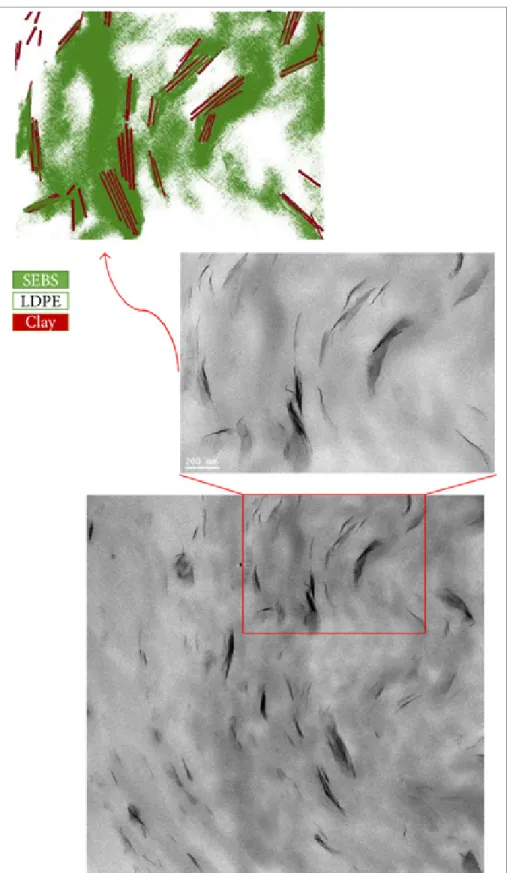
3.3.2 Scanning (SEM) & Transmission electron microscopy (TEM) ... 36
3.3.3 Rheological properties ... 43
3.3.4 AC short-term breakdown strength ... 45
3.3.5 DC short-term breakdown strength ... 52
CHAPTER 4 ARTICLE 2: CHARGE TRANSPORT AND ACCUMULATION IN
CLAY-CONTAINING LDPE NANOCOMPOSITES ...57
4.1 Introduction ...58
4.2 Experimental ...59
4.2.1 Materials and Processing ... 59
4.2.2 Characterization ... 61
4.3 Results and Discussion ...63
4.3.1 Electrical DC conductivity ... 63
4.3.2 Space Charge Measurement ... 69
4.4 Conclusion ...76
CHAPTER 5 ARTICLE 3: DIELECTRIC RELAXATION DYNAMICS OF CLAY-CONTAINING LDPE BLENDS AND NANOCOMPOSITES ...79
5.1 Introduction ...80
5.2 Experimental ...82
5.2.1 Materials and Processing ... 82
5.2.2 Measurements and Characterizations ... 83
5.2.3 Fitting Procedure ... 84
5.3 Results and Discussion ...85
5.3.1 Thermal Properties ... 85
5.3.2 Low-field Dielectric Measurement ... 87
CHAPTER 6 ARTICLE 4: EFFECT OF BLENDING AND NANOCLAY ON DIELECTRIC PROPERTIES OF POLYPROPYLENE ...103
6.1 Introduction ...104
6.2 Experimental ...106
6.2.1 Materials and Processing ... 106
6.2.2 Measurements and Characterization ... 107
6.3 Results and Discussion ...109
6.3.1 X-ray Diffraction ... 109
6.3.2 Scanning Electron Microscopy (SEM) ... 111
6.3.3 Rheological Properties ... 113
6.3.4 Low-field Dielectric Measurements ... 114
6.3.5 Space Charge Measurements ... 118
6.3.6 Short-term AC Breakdown Strength ... 119
CONCLUSION 123 RECOMMENDATIONS ...127
LIST OF TABLES
Page Table 3-1 Composition and nomenclature of LDPE/SEBS blends and
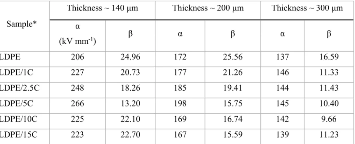
nanocomposites ( n=1, 2.5, 5, 10 & 15) ...31 Table 3-2 Weibull parameters for AC breakdown test of LDPE/clay
nanocomposites. ...48 Table 3-3 Weibull parameters for DC breakdown test of LDPE/clay blends and
nanocomposites. ...54 Table 5-1 TGA data of LDPE and its blend, nanocomposites and source
masterbatch ...87 Table 5-2 Optimum fit parameters for LDPE/MA/15C ...96
LIST OF FIGURES
Page
Figure 1-1 Materials and characterization methods employed in this study ...4
Figure 2-1 Electricity generation and transmission ...7
Figure 2-2 Thick underground cable next to smaller overhead conductor (Photo courtesy of Georgia Transmission Corporation)...8
Figure 2-3 Common design elements of high voltage cable (from www.openelectrical.org) ...9
Figure 2-4 Nanoparticles’ geometrical representation a) iso-dimensional, b) nanotubes and c) layered crystals. ...13
Figure 2-5 Crystal structure of 2:1 layered silicates Reproduced from (Beyer 2002) 16 Figure 2-6 Different structures of polymer layered silicates (PLS) nanocomposite, reproduced from (Albdiry, Yousif et al. 2013) ...17
Figure 2-7 Schematic of melt intercalation method reproduced from (Ray and Okamoto 2003) ...19
Figure 2-8 Basic types of phase structures in polymer blends ...22
Figure 2-9 Chemical Structure of SEBS ...24
Figure 2-10 Domain Structure of SEBS (from www.eastman.com) ...25
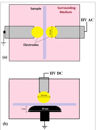
Figure 3-1 Electrical breakdown measurement setup for: a) AC short term, b) DC short term ...34
Figure 3-2 X-ray diffraction pattern for LDPE nanocomposites: (a) Parallel emission and (b) perpendicular emission ...36
Figure 3-3 SEM (a) and TEM (b) micrographs for LDPE/5C ...37
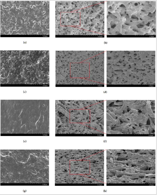
Figure 3-4 SEM micrographs of LDPE blends before and after solvent extraction: (a) and (b) LDPE/SEBS, (c) and (d) LDPE/SEBS//5C, (e) and (f) LDPE/SEBS-MA, and (g) and (h) LDPE/SEBS-MA/5C. ...39
Figure 3-5 TEM micrograph of LDPE/SEBS/5C (schematic phase representation on top) ...42
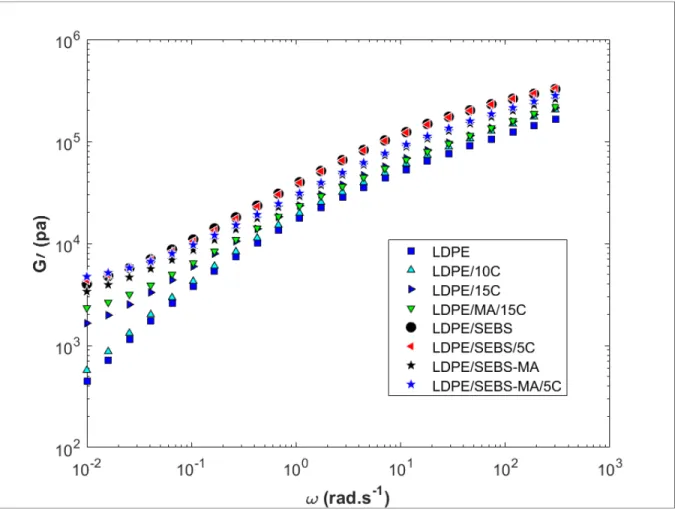
Figure 3-6 SAOS measurements of LDPE, SEBS blends and Clay-reinforced nanocomposites: Storage modulus (G’) as function of angular frequency
(ω) ...44
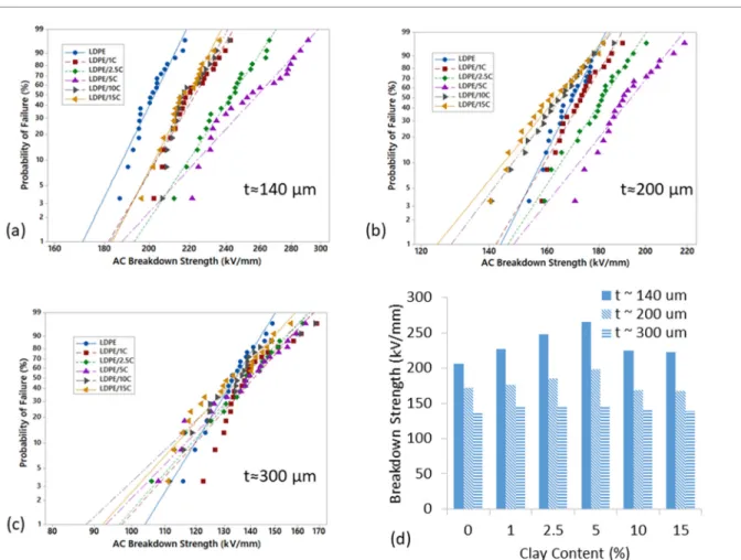
Figure 3-7 Weibull probability plots of LDPE/clay nanocomposites with different thicknesses: (a) 140 μm, (b) 200 μm, and (c) 300 μm. Comparison of the characteristic breakdown strength (d). ...47
Figure 3-8 Weibull probability plots of LDPE/MA/clay nanocomposites (a) and LDPE/SEBS blends and nanocomposites (b). ...51
Figure 3-9 Weibull plots of LDPE nanocomposites reinforced with clay (a) and blends of LDPE and two types of SEBS along with their corresponding nanocomposites containing 5% of clay. ...53
Figure 4-1 Micrographs of LDPE/5C: a) SEM and b) TEM ...60
Figure 4-2 Experimental setup for the conduction current measurement ...61
Figure 4-3 Schematic representation of the PEA setup ...62
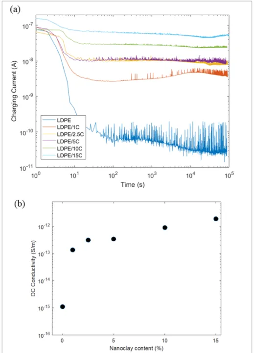
Figure 4-4 a) Charging currents of LDPE and its nanocomposites at 30 ˚C and under applied DC electric field of 50 kV/mm; b) calculated DC conductivities from steady state part of the charge currents ...65
Figure 4-5 Effect of field variation (a) and Temperature (b) on charging currents of LDPE and LDPE/2.5C at 30 ˚C ...68
Figure 4-6 Space charge patterns for LDPE and LDPE/5C nanocomposites at 20 ˚C under different applied electric fields ...70
Figure 4-7 Maximum recorded electric field during the polarization period corresponding to the space charge patterns of Figure 3-5 ...72
Figure 4-8 Space charge patterns for LDPE and its clay-containing nanocomposites at 60 ˚C and 50 kV/mm of applied electric field. ...74
Figure 4-9 Space charge patterns for LDPE and LDPE/5C at 60 ˚C under 70 kV/mm of applied electric fields ...75
Figure 4-10 Space charge profile for LDPE/5C at 60 ˚C under 70 kV/mm applied electric field. ...76
Figure 5-1 TGA decomposition curves of neat LDPE, its nanocomposites and the source masterbatch in nitrogen atmosphere ...86
Figure 5-2 Plots of real (a) and imaginary (b) parts of the permittivity for the neat LDPE versus frequency at different temperatures ...88 Figure 5-3 Dielectric loss (ϵ") of nanocomposites as a function of frequency in
different temperatures for different clay loadings: a) 2.5%, b) 5%, c) 10%, and d) 15% ...89 Figure 5-4 Arrhenius plot for the relaxation rate of the low frequency (filled) and
high frequency (unfilled) relaxation processes with their corresponding activation energies calculated from Arrhenius equation. ...91 Figure 5-5 Δε of the (a) MWS and (b) dipolar relaxations of LDPE/nC as a function
of reciprocal temperature. ...92 Figure 5-6 Shape parameters of the MWS (a&b) and dipolar (c&d) relaxations of
LDPE/nC as a function of reciprocal temperature. ...93 Figure 5-7 Dielectric loss (ϵ") of nanocomposites containing 5% MA as a function of
frequency in different temperatures for different clay loadings: a) 2.5%, b) 5%, c) 10%, and d) 15% ...95 Figure 5-8 An example of fitting corresponding to LDPE/MA/15C at 90 ˚C ...97 Figure 5-9 Dielectric loss (ϵ") as a function of frequency and temperature:
a)LDPE/SEBS, b)LDPE/SEBS-MA, c)LDPE/SEBS/5C, d)MA/5C. Fitting at 90 ˚C for e)LDPE/SEBS/5C and f)
LDPE/SEBS-MA/5C. ...100 Figure 6-1 X-ray diffraction patterns for polypropylene/clay nanocomposites ...110 Figure 6-2 Scanning electron microscopy micrographs of PP-clay nanocomposites in
different concentrations ...111 Figure 6-3 SEM micrographs of PP/SEBS-5 before (left) and after (right) solvent
extraction...112 Figure 6-4 Schematic representation of morphology development during
melt-mixing ...113 Figure 6-5 SAOS measurements of clay-reinforced nanocomposites: storage modulus (left) and complex viscosity (right) as function of angular frequency ...114 Figure 6-6 Dielectric loss (ϵ") as a function of frequency and temperature for: a)
PP-5, c) PP-15 and e) PP-SEBS-5. Fitting at 90 ˚C for b) PP-PP-5, d) PP-15 and f) PP-SEBS-5 ...117
Figure 6-7 Space charge patterns for PP and its blend and nanocomposites at 30 ˚C and under 50 kV/mm of applied electric field (Stored charge was
measured at the end of polarization period). ...119 Figure 6-8 Weibull probability plots of PP/clay and PP/SEBS/clay nanocomposites
LIST OF ABREVIATIONS
AC Alternating current
Al2O3 Aluminum oxide or Alumina
AlN Aluminium nitride
BDS Broadband dielectric spectroscopy
BN Boron nitride
CNT Carbon nanotubes
DC Direct current
DMA Dynamic mechanical analysis
DSC Differential scanning calorimetry
E Electric field
FTIR Fourier transformed infrared spectroscopy
GO Graphene oxide
HDPE High density polyethylene
HRSEM High resolution scanning electron microscopy
HV High voltage
HVAC High voltage alternating current HVDC High voltage direct current
LDPE Low density polyethylene
MA Maleic anhydride
MgO Magnesium oxide
MMT Montmorillonite
MWS Maxwell Wagner Sillars (polarization)
PE Polyethylene
PEB Poly(ethylene-co-butylene)
PEO Polyethylene oxide
PMMA Poly(methyl methacrylate)
POE Polyolefin elastomer
POSS Polyhedral oligomeric silsesquioxane
PS Polystyrene
SAOS Small amplitude oscillatory shear SAXS Small angle X-ray scattering
SBR Styrene-butadiene rubber
SEBS Polystyrene-b-poly(ethylene-co-butylene)-b-polystyrene
Si3N4 Silicon nitride
SiC Silicon carbide
SiO2 Silicon dioxide or Silica
TEM Transmission electron microscopy
TiO2 Titanium oxide
VFT Vogel Fulcher Tammann equation
XLPE Crosslinked polyethylene
LIST OF SYMBOLS
G’ Storage modulus
G’’ Loss modulus
t Thickness
T Temperature
tanδ Loss tangent or dissipation factor in BDS measurements
Tg Glass Transition
Tgi Interfacial Glass Transition
Wa Wetting coefficient
δ Surface tension
Δε Dielectric strength
ε Complex dielectric permittivity ε’ Real part of dielectric permittivity ε’’ Imaginary part of dielectric permittivity
η* Complex viscosity
λ Thermal conductivity
σ Conductivity modulus
σ’ Real part of complex conductivity
τ Relaxation time
CHAPTER 1: INTRODUCTION
1.1 Overview and research problem
Insulating systems are a very important part of any high voltage (HV) apparatus and require well design and adequate reliability. An interesting example is the insulating materials that are being used in high voltage power cables for transmitting power over long distances. They are constantly subjected to increasing electrical and thermal stresses as the demand for electricity increases worldwide. New power cables require more durable insulation to meet the growing operating voltages and power ratings. To address this urgent need a huge amount of research has been conducted in recent decades to develop new reliable and cost-effective insulating materials for HV cables. This has led to the introduction of nanocomposites as potential candidates to replace the existing insulating materials, known as “Nanodielectrics” (Lewis 1994, Cao, Irwin et al. 2004, Tanaka 2005, Fréchette, Reed et al. 2006).
Current insulating materials used in HV power cables suffer from some drawbacks. In HV alternating current (HVAC) systems, XLPE or cross-linked polyethylene is the main choice due to its excellent electrical properties and thermo-mechanical stability even at elevated temperatures. However, crosslinking makes XLPE a thermoset material and therefore not recyclable which has recently raised a lot of concerns from the environmental point of view (Lawson 2013). Also, XLPE has shown to have serious issues when used in HV Direct current (HVDC) systems, i.e. the accumulation of space charges, which has led to industry sticking with older technologies such as paper-oil cables with a lot of disadvantages including cost of fabrication, installation and repair (Mazzanti and Marzinotto 2013).
1.2 Motivations
Nanodielectrics, mostly polymers reinforced with inorganic nanoparticles, are believed to feature promising properties as insulating materials in both HVAC and HVDC systems, despite the fact that their reliability and reproducibility massively depend on the quality of the dispersion of nanoparticles which is a challenging task to achieve (Fréchette, Larocque et al. 2008, Kindersberger, Tanaka et al. 2011, David and Fréchette 2013). During nanocomposite processing, the inorganic nanoparticles tend to form agglomerations due to their incompatibility with the organic polymers. This reduces the potential benefits of the nanoscale reinforcement and affects the suggested/proved abilities of nanodielectrics to enhance the functional properties (David and Fréchette 2013). Numerous attempts have been done by researchers to resolve and prevent the agglomeration of nanoparticles. Most popular techniques include addition of compatibilizer (Reichert, Nitz et al. 2000, Wang, Choi et al. 2001, Garcıa-López, Picazo et al. 2003, Hasegawa and Usuki 2004), functionalization of the surface of nanoparticles (Wu, Wu et al. 2008, Liu, Wang et al. 2009), and in situ polymerization or synthesis of nanoparticles (Shin, Simon et al. 2003, Fim, Basso et al. 2013, Hakim, Nekoomanesh et al. 2018).
A new approach in this regards is to selectively accommodate nanoparticles in a template matrix to control their quality of the dispersion and their spatial distribution. In particular, an immiscible blend as the matrix would offer the possibility to disperse the nanofiller according to its micrometric morphology and guide them towards final locations based on the affinity between nanoparticles and different phases in the blend matrix (Ray, Pouliot et al. 2004, Elias, Fenouillot et al. 2007, Elias, Fenouillot et al. 2008, Graziano, Jaffer et al. 2018). Thanks to their tunable microstructure, it is possible to selectively locate and disperse nanoparticles within the immiscible blend matrix and improve certain physical properties when the base materials are properly selected and processed.
1.3 Objectives
This Ph.D. project focuses on introducing novel polymeric materials with the help of nanotechnology in the aim of producing novel nanodielectrics for HV insulation systems and tailoring their functional properties in correlation with their microstructures. The new materials must be recyclable, have the ability to be easily processed and meet all the requirements for HV applications.
Low-density polyethylene (LDPE) and polypropylene (PP) were chosen as the base polymers due to their excellent electrical properties to produce advance nanodielectrics incorporating a natural clay, montmorillonite, as the nanoreinforcement. Attempts have been made to further modify the microstructure of such nanodielectrics via incorporating a compatibilizer and forming a blend matrix to host the nanofiller. In particular, two industrial grades of polystyrene-b-poly(ethylene-butylene)-b-polystyrene (SEBS) have been used to form a co-continuous blend with either LDPE or PP to finely tune the dispersion and localization of the nanofiller. SEBS provides good level of electrical properties while is available commercially. It is consisted of two polystyrene PS endblocks within a hydrogenated polybutadiene midblock matrix, known as poly(ethylene-co-butylene) PEB. The rubbery midblock of SEBS has a similar structure as to the main chain of both LDPE and PP indicating an expected good level of compatibility. Melt mixing via extrusion was chosen as the main technique to prepare the nanodielectrics as it is the only viable approach in the industry. Within the framework of this research, it is expected that the obtained nanodielectrics possess enhanced electrical performance while having good thermo-mechanical properties.
1.4 Methodology
From the material point of view, this PhD project covers binary nanocomposites based on LDPE and PP incorporating different loadings of nanoclay. Blends of SEBS with LDPE and PP were used to accommodate certain loadings of clay. Also, the effect of a well-known compatibilizer on the microstructure and performance of LDPE/clay nanocomposites has been evaluated.
A co-rotating twin-screw extruder was used to process the materials. Extrusion is the most common process in manufacturing plastics in industry. A premixed polyolefin-based masterbatch presumably containing 50% organomodified montmorillonite was used as the source of the nanofiller, which was direct fed into the extruder along with the polymer powder to be diluted to the desired concentrations. Thus, series of LDPE/clay and PP/clay nanocomposites are achieved. the same procedure was used to create nanocomposite with compatibilizer. To Produce blend nanocomposites equivalent amounts of SEBS and total polyolefin were fed into the extruder to ensure that the co-continuous structure would be achieved. All the obtained pellets were then press-molded in an electrically heated hydraulic press into thin plates for characterization.
The microstructure of all the prepared nanocomposites were investigated using Scanning Electron Microscopy and Transmission Electron Microscopy. The degree of dispersion of clay was evaluated through X-ray diffraction. The dielectric performance was assessed by means of broadband dielectric spectroscopy, short-term AC and DC breakdown strength, space charge measurement and electrical conductivity.
1.5 Thesis Organization
This thesis in divided into 6 chapters consisting of an introduction and a brief literature review followed by 4 other chapters representing the outcome articles that are either published, accepted or submitted to related international journals.
In the first paper (chapter 3) the evolution of morphology and short-term breakdown strength of clay-containing LDPE blends and nanocomposites have been discussed. Nanoclay’s dispersion/distribution states and its effect on development of co-continuous morphology of LDPE/SEBS blends are fully addressed. Also the improvement mechanism of nanoclay on breakdown strength of nanocomposites is explained.
In chapter 4 (paper 2) charge transport and accumulation in LDPE/clay nanocomposites are discussed. A correlation of DC conductivity and space charge measurements is used to have a general view towards charge trapping and transfer within the materials.
Chapter 5 (paper 3) provides an in-depth evaluation of the dielectric spectra of clay-containing LDPE blends and nanocomposites. When necessary, the spectra are fitted to theoretical models to more clarify the outcomes.
In chapter 6 (paper 4) the morphology and electrical properties of blends and nanocomposites based on PP are investigated. Finally, conclusions and recommendations for future works are provided following the last chapter.
CHAPTER 2
POLYOLEFIN NANOCOMPOSITES FOR HV INSULATIONS
2.1 Transmission of electric energy
The main objective of the power system is to provide electrical energy from power source to the consumers in a safe and reliable way at the lowest possible cost (Figure 2-1). The bulk movement of electrical energy from a generating site, usually in remote areas, to an electrical substation near cities is called the electric power transmission. This is possible with the help of interconnected lines facilitating this movement known as a transmission network. The electrical energy received in HV substation is then transferred to customers through local wiring known as electric power distribution. The combined transmission and distribution network is known as the "power grid".
Figure 2-1 Electricity generation and transmission
The electrical distribution systems were somewhat fully developed during the twentieth century by connecting the consumers and generators using national and international grids. Despite the development, the current electrical transmission network needs to be strengthened
to transmit huge amounts of power long distances across continents. In North America, the power grid is highly integrated as there are over 35 electric transmission interconnections between the Canadian and US power systems. This integration is set to continue expanding, with multiple cross-border transmission projects currently being developed.
Throughout the grid, electricity is being transmitted at high voltages (>115 kV) to reduce the energy loss. The two main means of HV transmission are overhead and underground power transmission lines. HV overhead transmission lines are a reliable, low-cost, easily maintained and established method to transport bulk electricity across long distances. Their conductors (aluminum or copper) are not covered by insulation and are, therefore, exposed and vulnerable to adverse weather conditions.
Figure 2-2 Thick underground cable next to smaller overhead conductor (Photo courtesy of Georgia Transmission Corporation)
Underground cables, on the other hand, take up less right-of-way, have lower visibility, and are less affected by weather conditions. However, costs of insulated cable and excavation are much higher. Also, faults take longer time to locate and repair. The cable lines are attractive for crossing wide metropolitan areas or long distances in the open sea. The focus in this work is on the advances in insulating materials used in HV underground cables.
The use of HV power cable is increasing in recent years. Increasing of population of urban areas in industrialized countries has led to the increasing of energy consumption where the use of power cable is the only viable option. Power cables eliminate the environmental problems that are associated with the overhead transmission lines. Many developing countries have changed their power system network to meet the increasing of demand by using power cables. Also, parts of the existing power cable networks have reached the end of their lifetime and need to be replaced.
2.1.1 Extruded HV power cables
A cable includes a conductor and insulation, and is suitable for being run underground or underwater. High voltage power cable has a common design, independent of its operating voltage and frequency. Basically it consists of the conductor, the insulation, the inner and outer semi-conductive screens, earthed metallic screen and protection sheath that form long concentric cylinder. Figure 2-3 shows a common design of a high voltage cable.
Figure 2-3 Common design elements of high voltage cable (from www.openelectrical.org)
The insulation is the most critical part in cable structure due its crucial task to withstand a long term electrical stress during the service life of the cable. The use of extruded synthetic insulation in single layer construction is increasing due to its advantages in relatively easy
processing and handling of this insulation. This insulation can be selected to have 10% lower dielectric losses than cellulosic paper, higher intrinsic breakdown strength four times as high as impregnated paper insulation (Ryan 2001). The disadvantage is that a single defect can produce large influence on the whole insulation due to its homogeneity of this type of insulation (Ryan 2001).
2.1.2 HVAC versus HVDC systems
The first high voltage transmission line goes back to 1882, thanks to Thomas Edison, when a 45-km High-voltage direct-current (HVDC) link was constructed to connect Miesbach and Munich using rotating DC machines at each end. Later on, alternating-current generation, transmission, and utilization started to be dominant (Long and Nilsson 2007). They were realized to be more favorable because of benefitting from efficient and easy-to-manufacture transformers instead of high cost convertors that are necessary in DC lines. Voltage conversion in AC systems is simply via AC transformers achieved with low losses and little maintenance that allows high power and insulation levels within one single unit. Therefore, shortly after AC technology was introduced, it was accepted as the only feasible technology for generation, transmission, and distribution of electrical energy (Siemens 2011).
However, the inductive and capacitive elements of cables limit the transmission distance of AC transmission links. There are induced loss in all parts of AC cables. Also direct connection between two AC systems with different frequencies is not possible. Whereas HVDC transmission lines have no range limit, can be directly connected, and their only loss is the ohmic loss in conductor.
Nonetheless, the differences between extruded cables designed for a HVAC system and those designed for a HVDC system are negligible and the same structural components are required. Under the AC current, the insulation layer will experience electrical stress according to (Krueger 1991):
( ) =
. (1-1)
Where U is the operating voltage, R and r are the external and internal radius of insulation and x is the radius of the insulation where the electrical stress is determined by the equation above. Therefore, there is an electric field distribution within the insulation of a HVAC cable.
In HVDC cables, the electric field is temperature and time dependent and is determined by the local electrical resistance and thus by the electrical resistivity/conductivity of the insulation. This means that if the DC insulation resistivity were constant with temperature and electric field, then the field distribution in an HVDC cable would be identical to that of an HVAC cable of the same geometry (Mazzanti and Marzinotto 2013). Moreover, the phenomena of field inversion and space-charge accumulation are the cause of a significant distortion of the electric field with respect to the capacitive field distribution typical of AC cables.
2.1.3 Insulating materials for HV cables
Apart from mechanical stability and extrudability, a dielectric to be chosen for realizing the insulation of both HVAC and HVDC cables should have high breakdown strength and lowest possible thermal resistivity. HVAC cable insulation must show low losses, while in HVDC systems low space charge retention properties are important.
Most of the cable insulation materials for both AC and DC applications are based on polyethylene (PE). PE is a semicrystalline polymer that has good electrical properties (low dielectric constant, low dielectric loss, and high breakdown strength) together with other desirable properties such as mechanical toughness and flexibility, good resistance to chemicals, easy processing, and low cost. Its main drawback is the low melting temperature. This restricts the maximum operation temperature to 75°C. To improve this property, PE is cross-linked (XLPE). Crosslinking increases maximum operation temperature to 90°C, the emergency temperature to 130°C, and the short-circuit maximum temperature to 250°C. Crosslinking also
increases impact strength, dimensional stability, tensile strength, thermal properties, chemical resistance, and it improves electrical properties, aging, and solvent resistance of polyethylene. However, crosslinking makes XLPE a thermoset polymer, therefore non-recyclable. This is a drawback that cannot be easily tolerated nowadays as the trend is that the environmental issues must be addressed. In addition, the cross-linking by-products within XLPE can create an irregular distribution of the dielectric stress and often cause the formation and growth of storage centers of space charge that remains trapped within the dielectric.
Attempts to use XLPE for HVDC cables were not successful, as it tends to accumulate space charge over time. For this reason, at present most HVDC installations in service all over the world use paper–oil insulated cable, mostly mass impregnated non-draining (MIND) whose insulation is pure cellulose paper impregnated with oil and resin, since these cable systems have shown very high service reliability and good resistance towards space charge accumulation (Ildstad, Sletbak et al. 2004). However, paper–oil insulated cables have operational limitations (service temperature and installation length) and environmental issues. They also have a rather complex and expensive manufacturing process.
It is obvious that there is a need for improvement in the insulating materials used for both high voltage AC and DC power cables. To meet the environmental issues, the material of choice for insulation layer must be recyclable. This can easily be satisfied by extruded cables having a thermoplastic as the insulation layer. Apart from adequate mechanical flexibility, in all applications high breakdown strength, low thermal resistivity and low moisture absorption are needed. In the case of HVAC cable insulation, the amount of energy loss must be as low as possible, while in HVDC systems low space charge retention properties are important.
Therefore, this project aims to introduce a new formulation for HV cable insulating materials based on extrudable thermoplastic polymers, while improving their electrical properties by modifying the polymer via blending or by incorporating nano-reinforcements.
2.2 Polymer nanocomposites as the insulating materials for HV cables
2.2.1 Nanotechnology: Nanocomposites
Nanotechnology is a science that pursues knowledge and control of matter at scales ranging roughly from 1 to 100 nanometers, where unique phenomena generate new or improved physical, chemical, biological properties. Nanocomposites permit to obtain a combination of properties not achievable in the traditional composites. The main difference from the traditional composites is that the filler dimensions in the latter are above 1 μm while in the former the particles are in the order of 10 nm; furthermore, the filler loading required for an acceptable performance is typically an order of magnitude less in the nanocomposites.
To obtain the desired behavior it is necessary to have control over the size and distribution of the fillers and to understand the role of the interfaces between constituents that are chemically and structurally different. Due to the high surface area of the nanostructures, the strong interaction between the organic and inorganic phases permits to obtain an improved reinforcement of the polymer matrix, and so the nanocomposites exhibit unique properties.
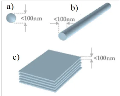
Figure 2-4 Nanoparticles’ geometrical representation a) iso-dimensional, b) nanotubes and c) layered crystals.
The particles to be dispersed could be, as represented in Figure 2-4, iso-dimensional when the three dimensions are in the order of nanometers, e.g. spherical silica nanoparticles, nanotubes or whiskers when two dimensions are on the nanometer scale, e.g. carbon nanotubes, cellulose whiskers, and particles in the form of sheets, such as layered crystals or clays.
2.2.2 Nanodielectrics: nanocomposites tuned for HV applications
The term “Nanodielectric”, short for nanometric dielectric, is assigned to a multicomponent dielectric processing nanostructures, the presence of which lead to changes in one or several of its dielectric properties (Lewis 1994). An important category of nanodielectrics are polymer nanocomposites. Nowadays, it is well-established that electrical properties of polymers can be significantly enhanced, as will be discussed later, upon addition of specific nanoparticles. Thus, nanodielectrics have gained attention for dielectric application including HV insulation (Fréchette, Reed et al. 2006, Fréchette, Larocque et al. 2008).
The extend of improvement in electrical properties of polymer nanocomposites, however, is hugely affected by the dispersion/distribution of nanoreinforcement and its interfacial area with the polymer matrix. Although these parameters are interrelated, the quality of interfacial area is also dependent to the nanoparticle size/area and their compatibility with the polymer host making it hard to predict the electrical properties of these specific materials. Nonetheless, several models have been introduced to describe the interfacial region in nanocomposites (Schönhals and Kremer 2003, Tanaka 2005, Zou, Fothergill et al. 2007, Pitsa and Danikas 2011).
Different types of nanometric filler particles have been used to prepare nanodielectrics. Metal oxide nanoparticles (MgO, Al2O3, SiO2, TiO2, ZnO, …) have been shown to significantly alter
the electrical properties of polymers, even in very low concentration. Improvement in breakdown strength and voltage endurance has been seen upon addition of some metal oxide nanoparticles into polymers (Ishimoto, Tanaka et al. 2008, David and Fréchette 2013). Also it is reported that metal oxide nanoparticles will reduce the mobility of charge carriers in the
polymer matrix resulting in an overall reduction of the electrical conductivity and space charge accumulation (Fleming, Pawlowski et al. 2005, Murakami, Okuzumi et al. 2010, Milliere, Makasheva et al. 2014, Park, Kwon et al. 2014, Du, Li et al. 2017, Wang, Wu et al. 2017).
Another interesting category of nanoparticles in this regards are nitride and carbide nanoparticles including silicon nitride (Si3N4), aluminium nitride (AlN), boron nitride (BN)
and silicon carbide (SiC). They show high thermal conductivities and are mostly tuned for electrical applications such as HV insulation systems and HV accessories (Huang, Jiang et al. 2011).
Finally, anisotropic nanoparticles have also been used for HV applications such as graphene oxide (GO) and graphene (Deshmukh, Ahamed et al. 2015, Mancinelli, Fabiani et al. 2015, Fabiani, Camprini et al. 2017), BN nanotubes and nanosheets (Golberg, Bando et al. 2010, Song, Wang et al. 2012, Heid, Fréchette et al. 2015), as well as nanoclay (Tomer, Polizos et al. 2011, Zazoum, David et al. 2014, David, Zazoum et al. 2015, Ghosh, Rahman et al. 2016). The anisotropy usually results in unique properties in preferential directions when purposefully aligned. In particular, nanoclay with layered structure and the ability to be easily dispersed is a great candidate for HV applications. More details about nanoclay and clay-containing polymer nanocomposites are discussed in the following sections.
2.2.3 Nanoclay
As defined by the Clay Mineral Society, clay is a “naturally occurring material composed primarily of fine-grained minerals, which is generally plastic at appropriate water contents and will harden when dried” (Guggenheim and Martin 1995). Smectite clays are the most used in nanocomposites as the inorganic particles especially montmorillonite. The crystal structure of layered silicates is built up of two tetrahedral sheets and one octahedral sheet. The structure 2:1 layered silicates are shown in Figure 2-5. The thickness of each layer is around 1 nm and the lateral dimension may vary from 30 nm to several microns. The layers are placed on the
top of each other’s forming stacks. These stacked layers have a van der Waals gap between layers, which is called the interlayer or gallery.
Figure 2-5 Crystal structure of 2:1 layered silicates Reproduced from (Beyer 2002)
Layered silicates have two particular characteristics that make them perfect for mixing with polymers to prepare polymer nanoclay nanocomposites. The first characteristic is the dispersion of layered silicates into individual layers in the polymer matrix and the second is the finely tuned surface made through cation exchange reactions with organic and inorganic cations. Both characteristics are dependent on each other, since the dispersion of layered silicate in a particular polymer is related to the interlayer cation (Ray and Okamoto 2003). Due to their hydrophilic nature and to be able to mix them with non-polar polymers, layered clays usually undergo an organic treatment on the surface to obtain satisfactory dispersion. The organic treatment is most of the time based on quaternary ammonium salts in a variety of chain lengths (Powell and Beall 2007, Choudalakis and Gotsis 2009).
2.2.4 Clay-containing polymer nanocomposites
The polymer layered silicates nanocomposites have been widely studied, and have shown markedly improved mechanical, thermal, and electrical properties compared to pure polymer or conventional, microscale (Ray and Okamoto 2003). Due to their high aspect ratio, the addition of clay in polymers can act as reinforcement in the same way as glass fiber or microscale inorganic nanofiller. Thus clay-containing polymer nanocomposites are expected to have unique characteristics.
Figure 2-6 Different structures of polymer layered silicates (PLS) nanocomposite, reproduced from (Albdiry, Yousif et al. 2013)
With regards to preparation, depending on the nature of the components and the method of preparation three main types of composites may be obtained as illustrated in Figure 2-6. In an intercalated structure, polymer chains intercalate between the layered structures of the clay and effectively expand the distance between the layers. Polymer chains penetrate inside the
galleries of layered silicates and make a “crystallographically regular fashion” structure. A flocculated structure conceptually is similar to an intercalated one; however, in this structure silicate layers become flocculated due to the hydroxilated edge-edge interaction. The last type is the exfoliated structure in which layered silicates are separated to their individual layers. The layers disperse continuously in the polymer matrix at random orientation and have an average distance with a value that is dependent on the amount of nanoclay loading.
2.2.5 Preparation methods of polymer/clay nanocomposite
Three main methods are generally available for preparation of polymer layered silicate nanocomposites. The differences between these methods are the result of the initial materials and the processing techniques used (Manias, Touny et al. 2001, Ray and Okamoto 2003, Albdiry, Yousif et al. 2013) :
Intercalation of polymer or pre-polymer from solution: Polymer or prepolymer is dissolved in a solvent (e.g. water, chloroform or toluene), which is appropriate for the dispersion of the silicate layers. The polymer chains intercalate into the interlayer silicates in the solution phase and remain in the intercalated structure after removal form the solvent. This method is limited to a limited number of polymers, which have a suitable and available solvent that is also suitable for the clay. It is useful for producing polymer nanocomposites with little or no polarity. However, this method is not commercially viable because of high cost of solvent recovery, making it environmentally unfriendly.
In situ intercalative polymerization method: In this method, the silicate layers disperse within the liquid monomer or monomer solution. The polymerization process can be initiated by heat or radiation, suitable initiator or fixed catalyst, which leads to the formation of an exfoliated structure. Most factors, including the requirement for separate production lines or major changes to existing production facilities, limit the commercialization of this method.
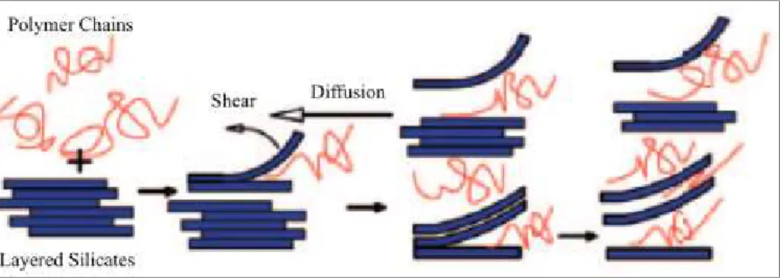
Melt intercalation method: Structurally, polymer/layered silicates are prepared under annealing polymer glass transition or melting temperature conditions, as well as shear mixing. Above their softening point polymer chains move easily, and can intercalate between silicate layers. In Figure 2-7, a schematic of the melt intercalation method is shown. This preparation method is environmentally friendly and economically favorable compared to other methods because of the absence of solvents in this technique. In addition, evidence suggests that a conventional processing technique, such as the twin-screw extruder, is an effective way for the dispersion of layered silicates within the polymer (Vaia and Giannelis 1997). A range of nanocomposite structures, from intercalated to exfoliated, can be obtained by this method.
Figure 2-7 Schematic of melt intercalation method reproduced from (Ray and Okamoto 2003)
2.2.6 Effect of nanoclay on electrical properties of polymers
Extensive research has been carried out on clay nanocomposites. Clay-containing nanocomposites have already been used in many applications and the processes to achieve organically modified clays are well-developed. Clay dispersion in polymer materials has shown to improve fundamental properties including mechanical properties (Lan and Pinnavaia 1994), thermal properties (Messersmith and Giannelis 1994) and electrical insulation properties (Lee and Lin 2006). Clay dispersion can impart new functional properties in polymer materials such as gas barrier (Yano, Usuki et al. 1993) and flame resistance (Zhu, Morgan et al. 2001).
They are also reported to have enhanced dielectric properties, i.e. higher breakdown strength comparing to the neat polymer. This is possible thanks to the high aspect ratio and surface area that increase the tortuosity and scattering opposing the flow of charge carriers, especially when clay layers are oriented (Tomer, Polizos et al. 2011, David, Fréchette et al. 2013, Zazoum, David et al. 2014). Clay nanocomposites have also shown to have higher resistance to PD erosion than the base polymer (Kozako, Fuse et al. 2004) and delay electrical treeing propagation .
On the other hand, other important electrical properties of clay-containing nanocomposites such space charge accumulation have not been fully discussed. In this work, a comprehensive look will be given to the electrical properties of clay containing nanocomposites based on LDPE and PP including evaluating the dielectric spectra, the role of thickness in breakdown strength, dc conductivity and space charge accumulation.
2.3 Modified matrix: polymer blends
Modification of polymer matrix via blending is now a new trend to improve the dielectric and breakdown behavior of semi-crystalline polymers. This enhancement could be as a result of modification of the structure ordering and crystallinity of the polymer. Here the polymer blends and their morphology are briefly reviewed. At the end, readers will be introduced to SEBS, polystyrene-b-poly(ethylene-co-butylene)-b-polystyrene, as an excellent candidate to form a blend with polyolefin.
2.3.1 Polymer blends classification
A polymer blend is a mixture of two or more polymers that have been blended together to create a new material with different physical properties (Paul and Newman 1978). All-important performance properties can be improved by blend systems. Notable among the properties are flow, mechanical strength, thermal stability, and cost. From the morphological point of view, polymer blends can be classified into two main categories:
Miscible polymer blend, a polymer blend that is homogenous at a microscopic scale (i.e., achieving a state of equilibrium at a molecular level).
Immiscible polymer blend, a polymer blend that is at a phase-separated state of mixing at a molecular level with the composition of the separated phases pure or identical to the pure components prior to blending. This is the most common case of polymer blends due to the fact that most polymers are immiscible.
The morphologies of the miscible and immiscible polymer blends are distinct from each other. The miscible polymer blends exhibit single phase morphology. In an immiscible blend, two phases are present: the discrete phase (domain), which is lower in concentration, and the continuous phase, which is higher in concentration. In some cases, the two phases may not have a well-defined boundary (partially miscible). Each component of the blend penetrates the other phase at a molecular level. The molecular mixing that occurs at the interface of a partially miscible two-phase blend can stabilize the domains and improve the interfacial adhesion.
In this project, we are interested in the immiscible type of polymer blends, since their multiphase nature and controllable morphology works in the favor of being a good choice to help dispersing nanoparticles inside the polyolefin matrix. To achieve that, the interfacial chemistry and the dispersed phase morphology must be well-controlled. In particular, the control of the morphology of the dispersed phase under melt-processing conditions is of great importance due to the increasing interest in using melt compounding techniques in the mixing and dispersion of polymers.
2.3.2 Morphology of immiscible polymer blends
As multiphase materials, the properties of immiscible polymer blends are considerably influenced by their phase structure. The final morphology of a polymer blend prepared by melt mixing is a result of the complex relationships of inner and outer parameters. Besides the
chemical structure and rheological properties of pure components or blend composition as inner parameters, applied flow field or temperature as outer factors influence the morphology development to great extent. Therefore, by changing the composition of the blend or processing conditions it is possible to obtain materials with morphologies of different types (Robeson 2007).
Generally, the vast majority of immiscible polymer blends can be classified as a blend with either dispersed (droplet/matrix) or co-continuous morphology, as shown schematically in Figure 2-8. If the amount of component A is low, it forms a dispersed particles surrounded by a matrix of component B. Increasing the amount of phase A, the size of the dispersed domains grows and approaching the threshold of geometric percolation the first continuous structures appear. The morphology is considered co-continuous when both of the phases are fully continuous. With a further increase in the concentration of A, the structures of phase B disintegrate and finally the phases invert and A forms the matrix of the blend and B the dispersed phase.
Figure 2-8 Basic types of phase structures in polymer blends
In order to minimize the free surface energy of the system, the dispersed particles tend to achieve a spherical shape. However, many anisotropic particle shapes, such as ellipsoids, fibrils or platelets, can be observed in polymer blends as the final morphology is often quenched immediately after melt processing. Thus, any particles deformed by the shear and/or elongational stresses applied in the mixing devices are solidified before they can regain an energetically favorable spherical shape.
2.3.2.1 Morphology development during melt processing
Most of polymer blends are produced by melt-mixing from powders or pellets of pure components. In the initial stage of mixing the original, typically millimeter-sized solid particles are heated and sheared, and during melting the size of the domains decreases into the micro range. In this early mixing stage, the pellets in contact with the hot walls of a processing device are exposed to high shear stresses and disintegrate into thin sheets or ribbons (Scott and Macosko 1995). Subsequently, as the thickness of these sheets decreases in the micrometer range, the interfacial forces become important and holes are formed in the sheets. These lacey structures then break up into irregularly shaped particles, which in turn break up further or relax into near-spherical particles. This mechanism leads to a rapid decrease in the dispersed particle sizes during the first few minutes of mixing.
After the initial stage of mixing the domain size decreases only slightly such that, after some time, the phase structure no longer shows any changes. In this steady state time interval, the morphology is stable until thermal degradation alters the rheological properties of polymers considerably. The morphology development during mixing is a result of the competition between droplet deformation and break-up on one side, and droplet coalescence on the other side (Fortelný, Kovář et al. 1996). In steady-state mixing these two processes are in dynamic equilibrium, and this determines the final shape and size of the phase domains.
Another process influencing blend morphology is the coalescence of the dispersed particles. In contrast to droplet break-up, coalescence leads to an increase in droplet size and a coarsening of the phase structure. It is a consequence of the collision of droplets having different velocities. When two droplets approach each other, they begin to deform due to the axial force, and at the same time the matrix film between the particles is squeezed out. If the critical distance between the particles is reached, the matrix film ruptures and the droplets merge.
Overall, the development of the final morphology is a consequence of complex relationships between the viscosity and elasticity of the components, the processing conditions, the chemical
structure of the components, and the blend composition. Therefore, it is difficult to predict the shape, size and spatial arrangement of the phases.
2.3.3 SEBS to form blend with polyolefin
An interesting type of polymers are block copolymers. A block copolymer molecule contains two or more polymer chains attached at their ends. They can have different types of morphology (i.e. diblock, triblock …) depending on composition, thermodynamical affinity between components, rheological properties of phases, and history of processing conditions (Carastan, Amurin et al. 2013). When one block has a glass-transition temperature (Tg) above
ambient temperature and one below ambient temperature, the result is a micrometric mixture of hard and soft parts known as thermoplastic elastomers. This especial type of block copolymers behaves as a rubber at ambient conditions, but can be molded at high temperatures due to the presence of the glassy domains that act as physical cross-links. Thermoplastic elastomers can also be used as a host template for nanofillers. In fact, both immiscible blends and block copolymers constitute self-ordered structures with controllable morphologies offering various possibilities to disperse nanofillers, nanoclay platelets in our case, based on the affinity of the selected nano-charge to one phase or another.
Figure 2-9 Chemical Structure of SEBS
One interesting type of triblock copolymers is SEBS which is composed of polystyrene blocks at both ends and a rubber block at the middle. It is a thermoplastic elastomer that combines advantages of both rubbery and plastic materials. It features self-assembled nanodomains and exhibits excellent mechanical properties combining both the thermoplastic and the elastomer behaviors (Holden, Kricheldorf et al. 2004, Balsamo, Lorenzo et al. 2006, Carastan, Amurin
et al. 2013). The polystyrene end-blocks form domains that act as multifunctional junction points to give an elastomeric network and the cross-links are formed by a physical rather than a chemical process (Figure 2-9). Thus, at room temperature, the material behaves as a conventional vulcanized elastomer, but when it is heated, the domains soften, the network loses its strength and eventually the block copolymer can flow; the changes experienced by the material upon heating are completely reversible (Legge 1987).
Figure 2-10 Domain Structure of SEBS (from www.eastman.com)
When making a blend, SEBS is a great choice. Its hydrogenated polybutadiene midblock has a similar structure to LDPE and PP ensuring a good compatibility with polyolefins (Agari, Ueda et al. 1993). Also the relatively polar aromatic rings of PS block provide chemical affinity to some inorganic nanoparticles such as nanoclays (Carastan, Amurin et al. 2014, Kuester, Barra et al. 2016). SEBS and SEBS grafted maleic anhydride (SEBS-MA) can compensate for decreased toughness of clay-containing nanocomposites, especially based on PP, while maintaining the improved electrical properties. Apart from water treeing retardant agent (Ma, Jiang et al. 2010, Liu, Mhetar et al. 2011) and dielectric elastomer actuators (Mc Carthy, Risse et al. 2009, Kofod, Risse et al. 2011, Stoyanov, Kollosche et al. 2011), SEBS is now gaining attention as a recyclable polymer to form blend with polyolefin as insulating materials for HV applications, especially for HV cable insulation (Zhang, Zha et al. 2017).
In this work, two grades of SEBS have been used to modify the morphology of clay containing nanocomposites based on LDPE and PP. It is expected that SEBS and the resultant immiscible blend will act as a template matrix to control the dispersion/distribution of nanoclay and therefore directly affect the electrical properties of those nanocomposites.
CHAPTER 3
ARTICLE 1: ELECTRICAL BREAKDOWN PROPERTIES OF CLAY-BASED LDPE BLENDS AND NANOCOMPOSITES
M. Eesaee1, E. David1, N.R. Demarquette1, Davide Fabiani2
1 Mechanical Engineering Department, École de Technologie Supérieure,
Montréal, QC, Canada
2 Department of Electrical, Electronic, and Information Engineering,
University of Bologna, Bologna, Italy
This article has been published in:
Journal of Nanomaterials, Volume 2018, 11 January 2018, Article ID 7921725 https://doi.org/10.1155/2018/7921725
Abstract
Microstructure and electrical breakdown properties of blends and nanocomposites based on low-density polyethylene (LDPE) have been discussed. A series of LDPE nanocomposites containing different amount of organomodified montmorillonite (clay) with and without compatibilizer have been prepared by means of melt compounding. Two sets of blends of LDPE with two grades of Styrene-Ethylene-Butylene-Styrene block copolymers have been prepared to form cocontinuous structure and host the nanoreinforcement. A high degree of dispersion of oriented clay was observed through X-ray diffraction, scanning, and transmission electron microscopy. This was confirmed by the solid-like behavior of storage modulus in low frequencies in rheological measurement results. An alteration in the morphology of blends was witnessed upon addition of clay where the transportation phenomenon to the copolymer phase
resulted in a downsizing on the domain size of the constituents of the immiscible blends. The AC breakdown strength of nanocomposites significantly increased when clay was incorporated. The partially exfoliated and intercalated clay platelets are believed to distribute the electric stress and prolong the breakdown time by creating a tortuous path for charge carriers. However, the incorporation of clay has been shown to diminish the DC breakdown strength of nanocomposites, mostly due to the thermal instability brought by clay.
Keywords: Electrical breakdown strength, polymer blend, nanocomposite, clay, block copolymer
3.1 Introduction
It has been more than eight decades that synthetic polymers have been used as solid electrical insulating materials because of their excellent dielectric properties, the most important of which is the high dielectric breakdown strength. When a dielectric is subjected to a rising voltage, with a high enough applied electrical field the electrical pressure will eventually overcome the insulating material and electrical charge carriers will flow. Current flow behavior through an insulator is not linear as in conductors and practically no electrons will flow below a certain threshold level, above which current will gain sufficient kinetic energy and forcibly runs through the material. Electrons will multiply as a result of the ionization of the collision process, electronic conduction takes place and breakdown occurs. This mechanism is known as avalanche process (Zeller, Pfluger et al. 1984, Kao 2004) and the dielectric strength is defined as the highest voltage the insulator withstands before breakdown divided by its thickness. However, this is not the only known mechanism and breakdown may occur in advance of electron avalanche by insulation melting due to temperature rise (thermal breakdown), enhanced electric stress when the insulation thickness is mechanically reduced (electromechanical breakdown) or due to partial discharge (Dissado and Fothergill 1992, Zakrevskii, Sudar et al. 2003, Blythe and Bloor 2005, Tanaka 2016). In reality the mechanism of dielectric breakdown is more complicated in many polymers and pre-existing discontinuities also contribute to the cumulative breakdown. It was found out that impurities, defects and
degradation caused by electric field or heat will accelerate the failure (Jonscher and Lacoste 1984). Extensive works have been done to understand the behavior of polymers towards electrical breakdown which has led to considering several factors such as thickness, surrounding medium, pressure and temperature, all along with the complicated morphology and structure of polymers which make the understanding of breakdown process very difficult.
One proposed solution to improve the breakdown strength of polymers consists of adding a reinforcing inclusion as fillers (composites). Despite improvements in mechanical and thermal properties, micro inclusions are believed to decrease the breakdown strength of polymers as they may act as defects (Wang, Iizuka et al. 2011). Consequently, nanofiller inclusions have been introduced recently to overcome the negative effects (Cao, Irwin et al. 2004, Tanaka 2016), thus creating a new area of materials called nanometric dielectrics or nanodielectrics (Lewis 1994). Nanoparticles which may be chemically modified with different approaches in order to have polar or non-polar functional groups on their surface have shown very promising results (Li, Yin et al. 2010). It is well known that they have a great influence on breakdown properties of polymers, especially by the change in morphology of the semicrystalline polymers (Roy, Nelson et al. 2005). They reduce the internal field (Nelson, Fothergill et al. 2002) and alter the space charge distribution within the polymer matrix (Fabiani, Mancinelli et al. 2016). Furthermore, the interface between polymer and nanoparticle plays a crucial role in the dielectric breakdown performance (Lewis 2004, Zazoum, David et al. 2014). The final obtained morphology and the physical and chemical characteristics of the interface are greatly influenced by the dispersion and localization of nanoparticles, and the nature of both phases, which will eventually influence the breakdown process by changing the micro-scale aspects i.e. traps, free volume and carrier mobility (Li, Yang et al. 2016). Therefore, considerable attentions must be paid to tailor the interface with proper physical and chemical methods to obtain improved dielectric breakdown properties (Huang, Ma et al. 2009, Peng, Huang et al. 2010).
Another well-established approach to develop new materials is polymer blending (Robeson 2007). Since usually polymers have low mixing entropy, most polymer pairs tend to make an
immiscible blend (Coleman, Painter et al. 1995). During the mixing process and at rest, the dynamic interplay between rheological phenomena determines the final morphology of the blend. When having different mixing proportion, the minor component tends to distribute all over the major phase as droplets. However, in a narrow range of composition with proper processing, the blend microstructure can turn into co-continuous, distinguished by a mutual interpenetration of the two components. This type of microstructure is well-known for its tunable and substantial combination of functional and structural properties, but is hard to achieve (Pötschke and Paul 2003). It has been well-established that nanoparticles can be adopted to stabilize the morphology of immiscible blends (Filippone, Dintcheva et al. 2010, Kar, Biswas et al. 2015, Pawar and Bose 2015). However, this approach has not been fully employed to discover the potential improvements in electrical breakdown properties of polymers.
In this paper, attempts to evaluate the short-term AC and DC electrical breakdown properties for clay-based nanocomposites of low density polyethylene (LDPE) have been presented, alongside with observation of the morphology of those materials. Also the possibility of using a binary blend to achieve a tailored dispersion of nanoclays to result in an improved AC and DC electrical breakdown was evaluated.
3.2 Experimental
3.2.1 Materials and Processing
Commercially available premixed LDPE/Clay masterbatch (nanoMax®-LDPE) containing 50% organomodified Montmorillonite (O-MMT) was supplied from Nanocor and used as the source of the nanoreinforcement. The masterbatch was further diluted with low-density polyethylene (LDPE), supplied from Marplex in powder form with a density of 0.922 g/cm3
and MFI of 0.9 g/10 min (190 °C/2.16 kg), to the desired concentrations of clay. Maleic anhydride grafted linear low-density polyethylene (LLDPE-g-MA) was supplied from DuPont (Fusabond M603) and has been used as a compatibilizer. It has a density of 0.940 g/cm3 and